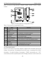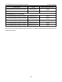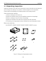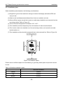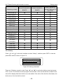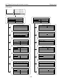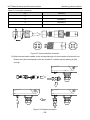
1
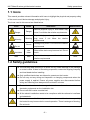
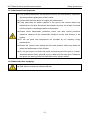
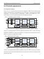
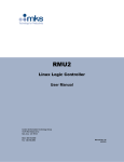
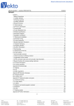
Operation Manual iMars B Series Grid-tied Solar Inverter Preface Thank you for purchasing iMars B series grid-tied solar inverters. iMars B series grid-tied solar inverters is mainly used in solar photovoltaic grid system. As a non-isolation and high-efficiency string photovoltaic grid-tied inverter, it transfers DC energy generated by solar modules to sinusoidal AC energy and feedback to public grid. The energy has the same frequency and phase with the utility grid. The manual is intended to provide detailed information of installation, application, trouble shooting, precautions and maintenance of iMars B series grid-tied solar inverters. Please read this manual carefully and follow all safety precautions seriously before any moving, installation, operation and maintenance to ensure correct use and high performance of operation on the inverter. Configured monitoring and design software for iMars B series grid-tied solar inverters are also provided. Go to www.invt-solar.com and download the software installation package and use instructions. The inverter complies with local regulations and laws on grid feeding. The manual needs to be kept well and be available at all times. All rights reserved. The contents in this document are subject to change without notice. -1- INVT iMars B series grid-tied solar inverters Content Content Preface ........................................................................................................................................ 1 Content ....................................................................................................................................... 2 1 Safety precautions .................................................................................................................. 3 1.1 Icons ................................................................................................................................. 4 1.2 Safety guidelines ............................................................................................................... 4 2 Product overview .................................................................................................................... 7 2.1 Solar grid-tied power generation system ............................................................................ 8 2.2 Products appearance ........................................................................................................ 9 2.3 Name plates .................................................................................................................... 12 2.4 Technical parameters ...................................................................................................... 15 2.5 Dimensions and weight ................................................................................................... 16 3 Installation ............................................................................................................................. 18 3.1 Unpacking inspection ...................................................................................................... 19 3.2 Before installtion .............................................................................................................. 21 3.3 Mechanical installation .................................................................................................... 24 3.4 Electrical installation ........................................................................................................ 27 4 Operaiton ............................................................................................................................... 32 4.1 Inspection before operation ............................................................................................. 33 4.2 Grid-tied operation........................................................................................................... 33 4.3 Stopping .......................................................................................................................... 34 4.4 Daily maintenance ........................................................................................................... 34 5 Display panel ......................................................................................................................... 35 5.1 LED indicators ................................................................................................................. 36 5.2 Operation panel ............................................................................................................... 38 5.3 LCD screen ..................................................................................................................... 38 5.4 Functions operation ......................................................................................................... 39 6 Monitoring communication .................................................................................................. 48 6.1 Standard communication ................................................................................................. 49 6.2 Optional communication .................................................................................................. 51 7 Troubleshooting .................................................................................................................... 52 8 Contact us ............................................................................................................................. 55 -2- INVT iMars B series grid-tied solar inverters Safety precautions 1 Safety precautions This chapter describes various warning symbols in the operation manual of iMars series inverters. It is intended to provide the installers and the users with all safety information about installation, operation, and use of the inverter. -3- INVT iMars B series grid-tied solar inverters Safety precautions 1.1 Icons This manual provides relevant information with icons to highlight the physical and property safety of the user to avoid device damage and physical injury. The icons used in this manual are listed below: Icons Name Instruction Danger Serious physical injury or even death may occur if not follow the relative requirements Warning Physical injury or damage to the devices may occur if not follow the relative requirements Do not Damage may occur if not follow the relative requirements Hot sides Hot sides Sides of the device may become hot. Do not touch. Note Note Physical hurt may occur if not follow the relative requirements Danger Warning Do not Abbreviation Note 1.2 Safety guidelines The first thing after receiving is to check for any visible damage to the package or to the inverter. If there is something suspected, contact the shipping company and local dealer before installing. Only qualified electricians are allowed to operate on the inverter. Do not carry out any wiring and inspection or changing components when the power supply is applied. Ensure all power supplies are disconnected before wiring and checking and always wait for at least 5 minutes. Ensure that there is no electromagnetic interference from other electrical and electronic equipments on the installation site. Do not refit the inverter unauthorized. All the electric installation needs to be compliance with the national or local laws and standards. The temperature of individual parts or the enclosure of the inverter–especially the heat sink may become hot in normal operation. There is a danger of burning. Do not touch. -4- INVT iMars B series grid-tied solar inverters Safety precautions Do not open the cover of inverters unauthorizedly. The electrical parts and components inside the inverter are electrostatic. Take measurements to avoid electrostatic discharge during relevant operation. 1.2.1 Delivery and installation Keep the package and unit complete, dry and clean during storage and delivery. Please remove and install the inverter with two or more people, because of the inverter is heavy. Remove and install the inverter with appropriate tools to ensure safe and normal operation and avoid physical injury or death. The people also need mechanical protective measures, such as protective shoes and work clothes. Only qualified electricians are allowed to install the inverter. Do not put and install the inverter on or close to combustible materials. Keep the installation site away from children and other public places. Remove the metal jewelry such as ring and bracelet before installation and electrical connection to avoid electric shock. Do cover solar modules with light-tight materials. Exposed to sunlight, solar modules will output dangerous voltage. Max. input voltage of iMars BG1K5TL / BG2K2TL / BG3KTL does not exceed 500V; Max. input voltage of iMars BG4KTL / BG5KTL / BG6KTL does not exceed 550V; Max. input voltage of iMars BG6KTR / BG8KTR / BG10KTR / BG12KTR / BG15KTR does not exceed 1000V; otherwise inverter damage may occur. The positive and negative pole of solar modules can not be grounded, otherwise irrecoverable damage may occur. Ensure the proper grounding of the inverter, otherwise, improper connection or no grounding may cause stop of the inverter. Ensure reliable installation and electrical connection. Note: iMars B series grid-tied solar inverters are only for crystalline silicon solar modules. 1.2.2 Grid-tied operation Only qualified electricians are allowed to operate the inverter under the permission of local power departments. Ensure reliable installation and electrical connection before operation. Do not open the cover of inverter during operation or voltage is present. -5- INVT iMars B series grid-tied solar inverters Safety precautions 1.2.3 Maintenance and inspection Only qualified electricians are allowed to perform the maintenance, inspection, and components replacement of the inverter. Contact with the local dealer or supplier for maintenance. Firstly disconnect all power supplies of the grid to the inverter before any maintenance, and then disconnect the breakers and wait for at least 5 minutes until the inverter is discharged before maintenance. Please follow electrostatic protection norms and take correct protective measures because of the electrostatic sensitive circuits and devices in the inverter. Do not use parts and components not provided by our company during maintenance.。 Restart the inverter after settling the fault and problem which may affect the safety and performance of the inverter. Do not get close to or touch any metal conductive part of the grid or inverter, otherwise electric shock, physical injury or death and fire may occur. Please do not ignore the warning icons and instructions with “electric shock”. 1.2.4 What to do after scrapping Deal with the inverter as industrial effluent. -6- INVT iMars B series grid-tied solar inverters Product overview 2 Product overview This chapter mainly describes the appearance, packaging accessories, name plate, technical parameters and other information of iMars B series grid-tied solar inverters. -7- INVT iMars B series grid-tied solar inverters Product overview 2.1 Solar grid-tied power generation system The photovoltaic grid-tied power generation system consists of solar modules, grid-tied inverter, metering devices and public grid. iMars Grid-tied Solar Inverter Solar PV Modules Public Grid Feeding Meter Figure 2.1 Application of iMars grid-tied solar inverters Grid-tied solar inverter is the core of photovoltaic power generation system. The solar energy can be converted into DC electric energy through solar modules and then be changed into sinusoidal AC energy which has the same frequency and phase with the public grid by grid-tied solar inverters, and then be feeded into the grid. iMars B series grid-tied solar inverters are only applied in solar grid-tied power generation system and its DC input are only composed of crystalline silicon solar modules whose negative and positive poles are not grounded. Do not connect any AC loads between the inverter and breakers which is shown as the figure below: iMars Grid-tied Solar Inverter iMars Grid-tied Solar Inverter AC Loads Public Grid Public Grid √ Feeding Meter OFF OFF Feeding Meter OFF AC Circuit Breaker OFF AC Circuit Breaker Figure 2.2 Connection of inverters and AC breakers The recommended solar modules need to comply with IEC61730 Class A rating. -8- INVT iMars B series grid-tied solar inverters Product overview 2.2 Products appearance 2.2.1 Single-phase inverters Figure 2.3 and 2.4 are the internal circuit structure diagrams of iMars B series grid-tied solar inverters. The inverter has 1 DC switch(for the on-off of DC input), 1 invertering circuit of DC/AC single-phase, 1 AC grid-tied interface of single-phase, 1 “RS485” communication port, 1 “EXT” communication port and an operational panel with LCD display and buttons. iMars 1.5 ~ 3kW Solar Inverter Topology + _ L MPPT + _ DC to AC Grid-tied N PE DC Switch Communication Interface Controller LCD Display & Operation Figure 2.3 Internal circuit diagrams of iMars BG1K5TL / BG2K2TL / BG3KTL inverters In figure 2.3, the iMars BG1K5TL / BG2K2TL / BG3KTL inverter has 1 MPPT, of which, the inverter of BG1K5TL / BG2K2TL can support the connection of 1 string of solar modules and the inverter of BG3KTL can support 2 strings of solar modules. Track B Track A iMars 4~6kW Solar Inverter Topology + _ MPPT1 + _ Grid-tied N MPPT2 + _ + _ L DC to AC PE DC Switch Communication Interface Controller LCD Display & Operation Figure 2.4 Internal circuit diagrams of iMars BG4KTL / BG5KTL / BG6KTL inverters In figure 2.4, the iMars BG4KTL / BG5KTL / BG6KTL inverter has 2 MPPT respectively for two DC input area of Track A and Track B. And the inverter can support the connection of 4 strings of solar modules at the most. -9- INVT iMars B series grid-tied solar inverters Product overview Below is the structure of iMars BG1K5TL / BG2K2TL / BG3KTL / BG4KTL / BG5KTL / BG6KTL inverters: 8 1 9 2 10 3 11 4 ℃… ℃ 5 6 12 7 Figure 2.5 Products appearance of single-phase inverters Table 2-1 Parts instruction of single-phase inverters No. Name Instruction 1 Company logo 2 Safety precautions INVT 3 Cover 4 Operational panel LED indicators, LCD screen and buttons 5 DC input port For the connection of solar modules 6 DC switch On –off of the DC input 7 Communication port RS485 and EXT communication port 8 Installation groove For the connection of inverter and installation bracket 9 Screw holes To fasten the inverter on the installation bracket 10 Radiator 11 Name plate For rated parameters of the inverter 12 AC terminal For the connection of AC output 2.2.2 Three-phase inverters Figure 2.6 is the internal circuit structure diagrams of iMars B series three-phase grid-tied solar inverters. The inverter has 1 DC switch(for the on-off of DC input), 1 invertering circuit of DC/AC three-phase, 1 AC grid-tied interface of three-phase, 1 “RS485” communication port, 1 “EXT” communication port and an operational panel with LCD display and buttons. And the inverter has 2 - 10 - INVT iMars B series grid-tied solar inverters Product overview MPPT respectively for two DC input area of Track A and Track B. Of which, the inverter of BG6KTR / BG8KTR can support the connection of 4 string of solar modules and the inverter of BG10KTR / BG12KTR / BG15KTR can support the connection of 6 string of solar modules. iMars 6~15kW Solar Inverter Topology Track A + _ + _ DC to AC L2 Grid-tied L3 MPPT2 + _ Track B L1 MPPT1 + _ N PE DC Switch + _ Communication Interface LCD Display & Operation Controller + _ Figure 2.6 Internal circuit diagrams of iMars BG6KTR / BG8KTR / BG10KTR / BG12KTR / BG15KTR inverters Below is the structure of iMars BG6KTR / BG8KTR / BG10KTR / BG12KTR / BG15KTR inverters: 8 1 9 2 10 3 11 4 12 ℃… ℃ 13 5 14 6 7 Figure 2.7 Products appearance of three-phase inverters Table 2-2 Parts instruction of three-phase inverters No. Name 1 Company logo 2 Safety precautions 3 Cover Instruction INVT - 11 - INVT iMars B series grid-tied solar inverters No. Product overview Name Instruction 4 Operational panel LED indicators, LCD screen and buttons 5 DC input port For the connection of solar modules 6 DC switch On –off of the DC input 7 Communication port RS485 and EXT communication port 8 Installation hanger For the connection of inverter and installation bracket 9 Air duct For ventilation 10 Concave handle Foe removing and carrying 11 Cooling chamber Protect the radiator and fan 12 Name plate For rated parameters of the inverter 13 Screw holes To fasten the inverter on the installation bracket 14 AC terminal For the connection of AC output 2.3 Name plates There is name plate on the inverter and package. After receiving, please check the information of name plates are the ordered one. If not, please contact with the supplier as soon as possible. 2.3.1 Name plate on the package The information on the name plate of the package includes the inverter model, DC input parameters, and AC output parameters, operation temperature, protective degree, gross weight, certificate No., grid No., origin country, environmental logo, certification logo and brand information and so on. Certificate logo Green logo Product model AC output DC input Operation temperature and protection degree Gross weight Certificate No. Origin Certificate standard Serial No. xxxxxxxxxxxxxxxx Figure 2.8 Name plate on the package - 12 - INVT iMars B series grid-tied solar inverters Product overview 2.3.2 Name plate on the inverter The information on the name plate of the inverter includes the brand information, product name, product model, DC input parameters, AC output parameters, operation temperature, protective degree, gross weight, grid certificate standard, certificate No., certification logo, environmental logo, and serial No. of the product and so on. Product name Product model DC input AC output Operation temperature and protection degree Certificate standard Certificate No. Green logo xxxxxxxxxxxxxxxx Certificate logo Serial No. Figure 2.9 Name plate on the inverter 2.3.3 Models Table 2-3 Models of iMars B series grid-tied solar inverters Product name Model Rated output power (W) Single-phase grid-tied solar inverters iMars BG1K5TL 1500 Single-phase grid-tied solar inverters iMars BG2K2TL 2200 Single-phase grid-tied solar inverters iMars BG3KTL 3000 Single-phase grid-tied solar inverters iMars BG4KTL 4000 Single-phase (L, N, PE) - 13 - INVT iMars B series grid-tied solar inverters Product overview Product name Model Rated output power (W) Single-phase grid-tied solar inverters iMars BG5KTL 5000 Single-phase grid-tied solar inverters iMars BG6KTL 6000 Three-phase grid-tied solar inverters iMars BG6KTR 6000 Three-phase grid-tied solar inverters iMars BG8KTR 8000 Three-phase grid-tied solar inverters iMars BG10KTR 10000 Three-phase grid-tied solar inverters iMars BG12KTR 12000 Three-phase grid-tied solar inverters iMars BG15KTR 15000 Three-phase (L1, L2, L3, N, PE) Note: Refer to the product specifications in section 2.4 of iMars B series grid-tied solar inverters for detailed information. - 14 - INVT iMars B series grid-tied solar inverters Product overview 2.4 Technical parameters Table 2-4 Technical parameters of iMars B series grid-tied solar inverters Model DC input Single-phase BG2K2TL BG3KTL BG4KTL BG5KTL BG6KTL BG6KTR BG8KTR BG10KTR BG12KTR BG15KTR Max. DC voltage 500 500 500 550 550 550 1000 1000 1000 1000 1000 Starting voltage (V) (V) MPPT voltage(V) 100 100 100 100 100 100 200 200 200 200 200 180-450 180-450 200-450 200-500 200-500 200-500 250-800 250-800 250-800 250-800 250-800 Operation voltage (V) 200-450 200-450 210-450 200-500 200-500 200-500 250-800 250-800 250 - 800 300 - 800 380 - 800 1/1 1/1 1/2 2/1 2/1 2/2 2/2 2/2 2/3 2/3 2/3 1800 2500 3250 4300 5300 6250 6400 8400 10400 12500 15600 11x1 15x1 12x2 14x2 16x2 16x2 21x2 21x2 21x2 21x2 MPPT/string of each MPPT Max. DC power (W) Max. input current (A) 8x1 DC switch Rated output power (W) Optional 1500 2200 AC voltage(V)/ frequency(Hz) AC output Three-phase BG1K5TL Max. AC output current (A) Optional (Lockable-off) 3000 4000 5000 6000 8000 7.5 11 15 20 10000 12000 15000 20 24 320~460 / 47~51.5 26 29 10 13 >0.99(full load) 15 -0.9~+0.9(adjustable) Harmonic distortion < 3% Cooling Natural cooling Air cooling Maximum efficiency 96.90% 97.20% 97.30% 97.40% 97.60% 97.60% 97.50% 97.80% 98.00% 98.00% 98.00% European efficiency 96.00% 96.10% 96.30% 96.50% 96.50% 96.50% 97.00% 97.00% 97.50% 97.50% 97.50% MPPT efficiency 99.9% Protection degree IP65 Power consumption at night < 1W Isolation mode Transformerless Operation temperature -25℃~+60℃, derate after 45℃ Relative humidity 0~95%, no condensation Max. altitude(m) 1000 (derate if the altitude>1000) Displaying LCD LCD language English, Standard communication WiFi, Ethernet DC terminal Noise dB(A) Chinese RS485 Optional communication SUNCLIX water-proof terminal <52 ≤25 Installation mode Protection 6000 180~270 / 47~51.5 Power factor System Integrated (Lockable-off) Wall installation Overvoltage protection, DC isolation monitoring, DC monitoring, island protection, short circuit protection, overtemperature protection - 15 - INVT iMars B series grid-tied solar inverters Product overview 2.5 Dimensions and weight W D H Figure 2.10 Internal dimensions of BG1K5TL/ BG2K2TL/ BG3KTL inverters D W H Figure 2.11 Internal dimensions of BG4KTL/ BG5KTL/ BG6KTL inverters W D H Figure 2.12 Internal dimensions of BG6KTR/ BG8KTR/ BG10KTR/ BG12KTR/ BG15KTR inverters - 16 - INVT iMars B series grid-tied solar inverters Product overview Table 2-5 Inverters dimension and net weight H W D Net weight (mm) (mm) (mm) (kg) BG1K5TL / BG2K2TL / BG3KTL 460 335 175 16.5 BG4KTL / BG5KTL / BG6KTL 560 415 190 25.5 656 494 215 35 Model BG6KTR / BG8KTR / BG10KTR / BG12KTR / BG15KTR GRID-T D IED SO LA INVERT R ER ℃… ℃ W H Figure 2.13 Packages dimension Table 2-6 Packages dimension and gross weight H W D Gross (mm) (mm) (mm) weight (kg) BG1K5TL / BG2K2TL / BG3KTL 645 440 300 19.5 BG4KTL / BG5KTL / BG6KTL 780 550 320 29.5 825 620 350 41.5 Model BG6KTR / BG8KTR / BG10KTR / BG12KTR / BG15KTR - 17 - INVT iMars B series grid-tied solar inverters Installation 3 Installation This chapter describes how to install the inverter and connect it to the grid-tied solar system (including the connection between solar modules, public grid and inverter). Read this chapter carefully and ensure all installation requirements are met before installation. Only qualified electricians are allowed to install the inverter. - 18 - INVT iMars B series grid-tied solar inverters Installation 3.1 Unpacking inspection Inspect the information of the order and the name plate to ensure the product are the ordered one and no damage to the package. If any problem, contact the supplier as soon as possible. Put the inverter into the package if not used and protect it from humidity and dust. Check as following after unpacking: (1) Ensure no damage to the inverter unit; (2) Ensure the operation manual, port and installation accessories in the package; (3) Ensure no damage or loss to the items in the package; (4) Ensure the information of the order are the same as that of the name plate; (5) The delivery list of single-phase inverters is different from that of three-phase inverters. Below are the detailed lists: List of BG1K5TL / BG2K2TL / BG3KTL / BG4KTL / BG5KTL / BG6KTL inverters: INVT|User's manual iMars MD Series Grid-tied Solar Inverter 1 2 5 4 7 8 Figure 3.1 Packing list of single-phase inverters - 19 - 3 6 INVT iMars B series grid-tied solar inverters Installation Table 3-1 Detailed delivery list No. 1 Name Quantity BG1K5TL / BG2K2TL / BG3KTL / 1 BG4KTL / BG5KTL / BG6KTL inverters 2 Installation bracket 1 3 Operation manual of iMars B series 1 4 grid-tied solar inverters Hexagon assembling bolt M6*20 4 5 Screws M4*20 4 6 Communication connector 1 7 Expansion bolts M6*50 4 BG1K5TL / BG2K2TL:1 pair 8 BG3KTL:2 pairs DC connector BG4KTL / BG5KTL:2 pairs BG6KTL:4 pairs List of BG6KTR / BG8KTR / BG10KTR / BG12KTR / BG15KTR inverters: INVT|User's manual iMars MD Series Grid-tied Solar Inverter 1 2 5 4 7 8 Figure 3.2 Packing list of three-phase inverters - 20 - 3 6 9 INVT iMars B series grid-tied solar inverters Installation Table 3-2 Detailed delivery list No. 1 Name Quantity BG6KTR / BG8KTR / BG10KTR / 1 BG12KTR / BG15KTR inverters 2 Installation bracket 1 3 Operation manual of iMars B 1 4 series grid-tied solarbolt inverters Hexagon assembling M6*20 6 5 Screws M4*12 2 6 Communication connector 1 7 Expansion bolts M6*50 6 8 DC connector 9 AC connector BG6KTR / BG8KTR: 4 pairs BG10KTR / BG12KTR / BG15KTR: 6 pairs 1 Please check as the mentioned above. If any problem, contact the supplier as soon as possible. 3.2 Before installation 3.2.1 Installation tools Table 3-3 Tools list No. Installation tools Instruction 1 Marking pen Mark the installation hole 2 Electrodrill Drill in the bracket or wall 3 Hammer 4 Monkey wrench Hammer on the expansion bolts 5 Allen driver 6 Straight screwdriver 7 Megger 8 Multimeter Check the circuit and AC and DC voltage 9 Electric iron Weld communications cable Fix the installation bracket Fasten the screws, remove and install AC wiring box For AC wiring Measuring insulation performance impedance - 21 - and INVT iMars B series grid-tied solar inverters Installation 3.2.2 Installation place Select installation place based on the following considerations: (1) Height from ground level should be enough to ensure that display and status LEDs are easy to read. (2) Select a well ventilated place sheltered from direct sun radiation and rain. (3) Allow sufficient space around the inverter to enable easy installation and removal from the mounting surface. Refer to Figure 3.3. (4) The environment temperature is between -25℃~60℃. (5) The installation position keeps away from the interface of other electrical devise. (6) The inverter needs to be installed on a firm and sturdy surface, such as wall and metal bracket and so on. 450 (7) The installation surface should be perpendicular to the horizontal line. Refer to Figure 3.4. 200 450 200 Figure 3.3 Installation space Ensure there is sufficient space for heat-releasing. In generally, below space requirement should be met: Table 3-4 Detailed installation space Minimum clearance Lateral 200mm Top 450mm Bottom 450mm - 22 - INVT iMars B series grid-tied solar inverters Installation Figure 3.4 Installation position Do not remove any part and component of the inverter unintended; otherwise damage to the device and physical injury may occur. 3.2.3 Connection cables The user can select connection cable according the table below: Table 3-5 Cable specifications DC side Model AC side Cross-section Cross-section Mini cross-section (length ≤50m) mm² (length >50m) mm² mm² BG1K5TL 4 4 4 BG2K2TL 4 4 4 BG3KTL 4 4 4 BG4KTL 4 6 6 BG5KTL 4 6 6 BG6KTL 4 6 6 BG6KTR 4 6 4 BG8KTR 4 6 4 BG10KTR 4 6 6 BG12KTR 4 6 6 BG15KTR 4 6 6 3.2.4 Miniature circuit breakers It is recommended strongly to install circuit breakers or fuses at the DC input and AC output to ensure safe installation and running. - 23 - INVT iMars B series grid-tied solar inverters Installation Table 3-6 Breakers specifications DC input Model AC output Recommended DC breakers Recommended AC breakers (optional for length >100m) BG1K5TL DC500V, C10A, 2P AC240V, C10A, 2P BG2K2TL DC500V, C16A, 2P AC240V, C16A, 2P BG3KTL DC500V, C16A, 2P AC240V, C20A, 2P BG4KTL DC550V, C16A, 2P AC240V, C25A, 2P BG5KTL DC550V, C16A, 2P AC240V, C32A, 2P BG6KTL DC550V, C16A, 2P AC240V, C32A, 2P BG6KTR DC1000V, C20A, 2P AC400V, C16A, 4P BG8KTR DC1000V, C20A, 2P AC400V, C16A, 4P BG10KTR DC1000V, C20A, 2P AC400V, C20A, 4P BG12KTR DC1000V, C20A, 2P AC400V, C25A, 4P BG15KTR DC1000V, C20A, 2P AC400V, C32A, 4P 3.3 Mechanical installation Since the installation place can be made by different construction materials, the inverter can be installed by different mounting methods. Take the typical installation environment as the example, the manual describes how to install the inverter on concrete wall. And because of different structure, the single-phase and three-phase inverters have different instillation modes. The inverter should be mounted in a vertical position of 90°to the horizontal line as shown in figure 3.4. 3.3.1 Installation of single-phase inverters A 1 B 2 3 Figure 3.5 Installation bracket of single-phase inverters - 24 - INVT iMars B series grid-tied solar inverters Installation Table 3-7 Size of installation bracket Installation hole Model A(mm) B(mm) BG1K5TL / BG2K2TL / BG3KTL 210 285 BG4KTL / BG5KTL / BG6KTL 296 349 Table 3-8 Instruction of installation bracket No. Structure instruction 1 Installation holeΦ6 2 Screw hole M4 3 Installation hanger Installation steps of single-phase inverters: (1) Put the installation bracket against the wall and mark the position of 4 installation holes; (2) Drill in the wall according to the marked holes position; (3) Fix the expansion bolts into the 4 holes with hammer; (4) Fix the installation bracket on the bolts and ensure it is firm enough as figure 3.6 shows; (5) Hang the inverter on the installation bracket and ensure it is locked-in as figure 3.6 shows; (6) Fix the screws into the screw-holes to ensure fastened installation. 2 1 1 Figure 3.6 Installation of single-phase inverters - 25 - INVT iMars B series grid-tied solar inverters Installation 3.3.2 Installation of three-phase inverters A B/2 1 B/2 2 3 Figure 3.7 Installation bracket of three-phase inverters Table 3-9 Instruction of installation bracket Installation hole Model BG6KTR / BG8KTR BG10KTR / BG12KTR / BG15KTR A(mm) B/2(mm) 288 165 Table 3-10 Instruction of installation bracket No. Structure instruction 1 Installation hanger 2 Installation holeΦ6 3 Screw hole M4 Installation steps of three-phase inverters: (1) Put the installation bracket against the wall and mark the position of 6 installation holes; (2) Drill in the wall according to the marked holes position; (3) Fix the expansion bolts into the 6 holes with hammer; (4) Fix the installation bracket on the bolts and ensure it is firm enough as figure 3.8 shows; (5) Hang the inverter on the installation bracket and ensure it is locked-in as figure 3.8 shows; (6) Fix the screws into the screw-holes to ensure fastened installation. - 26 - INVT iMars B series grid-tied solar inverters Installation 3 2 1 Figure 3.8 Installation of three-phase inverters 3.4 Electrical installation This section proposes to describe detailed electrical installation and related safety instructions. Solar PV Modules QF O F F O F F O F F O F F O F F O F F O F F O F F iMars Grid-tied Solar Inverter Feeding Meter QF QF O F F O F F O F F O F F SPD Public Grid SPD Communication Converter Monitoring Equipment Figure 3.9 Block diagram of the grid-tied solar system Improper operation during the wiring process can cause fatal injury to operator or unrecoverable damage to the inverter. Only qualified personnel can perform the wiring work. All electrical installations must be in accordance with local and national electrical codes. All cables must be firmly attached, undamaged, properly insulated and adequately dimensioned. - 27 - INVT iMars B series grid-tied solar inverters Installation Read and follow the instructions provided in this section while observing all Note safety warnings. Always note the rated voltage and current defined in this manual. Never exceed the limits. The external ports are at the bottom of the inverter which is shown as figure 3.10, figure 3.11 and figure 3.12. 3 1 4 2 5 Figure 3.10 External ports of BG1K5TL / BG2K2TL / BG3KTL inverters 2 4 TrackB 3 TrackA 1 5 Figure 3.11 External ports of BG4KTL / BG5KTL / BG6KTL inverters 2 4 TrackB 3 TrackA 1 5 Figure 3.12 External ports of BG6KTR / BG8KTR / BG10KTR / BG12KTR / BG15KTR inverters Table 3-11 Port instruction No. External ports Instruction BG1K5TL / BG2K2TL / BG3KTL: On-off of DC input ; 1 DC switch BG4KTL / BG5KTL / BG6KTL / BG6KTR / BG8KTR / BG10KTR / BG12KTR / BG15KTR: On-off of DC input BG1K5TL / BG2K2TL: 1-string input 2 DC input terminal BG3KTL / BG4KTL / BG5KTL: 2-string input BG6KTL / BG6KTR / BG8KTR: 4-string input - 28 - INVT iMars B series grid-tied solar inverters No. Installation External ports Instruction BG10KTR / BG12KTR / BG15KTR: 6-string input 3 RS485 communication Standard RS485 port terminal Single-phase inverters: AC wiring box 4 AC output port 5 EXT communication terminal Three-phase inverters: pluggable wiring terminal Optional 3.4.1 Connection of solar modules 2 2 + - + - + 5 4 - + 1 1 - 3 - 3 2 2 + - 5 4 + Figure 3.13 Connection between DC connector and solar modules Connection steps: (1) Lighting, short-circuit and other protection measures which meet the local electrical safety laws and regulations are needed before the AC connection; Only qualified cables under the local electrical safety laws and regulations are allowed to connect. (2) Connect the output cables of solar modules to the DC connector as figure 3.13 shows. Loose the nut of connector and remove the isolation layer of the DC cable for about 15mm. Insert it into the connector and press until heart the lock sound. Finally fasten the nut. The wiring of negative pole is the same as that of the positive pole. Ensure the poles of solar modules are well connected with the connectors; The solar modules connected with the inverter needs to be the configured ones other than some connecting devices without authorized. Otherwise, device damage, unstable operation or fire may occur. - 29 - INVT iMars B series grid-tied solar inverters Installation (3) Connect the DC connector with the inverter and ensure tightly-fastened; (4) Insert the screw-driver into the hole of the connector to remove the connector form the inverter. (5) Unclench the pressed cover with screw-driver to remove the cables from the connector. 3.4.2 AC connection of single-phase inverters L N PE L N PE L N PE 5mm L N PE Figure 3.14 AC connection of single-phase inverters Connection steps of single-phase inverters: (1) Lighting, short-circuit and other protection measures which meet the local electrical safety laws and regulations are needed before the AC connection; Only qualified cables under the local electrical safety laws and regulations are allowed to connect. (2) Connect the cable of L, N and PE to the AC port according to figure 3.14. Ensure the cables are not exposed and fastened and the AC wiring box is locked. 3.4.3 AC connection of three-phase inverters 2 1 L N Figure 3.15 Three-phase AC connector - 30 - INVT iMars B series grid-tied solar inverters Installation Table 3-12 Port instruction of three-phase AC connector AC connector Three-phase 1 L1 (A) Remark 2 L2 (B) L L3 (C) N N neutral wire Connect PE grounding wire Connect The AC connector needs to correspond to the grid phase seriously. AC connector “1, 2 and L” corresponds to the “A phase, B phase and C phase” of the public grid. Connection steps of three-phase inverters: (1) Lighting, short-circuit and other protection measures which meet the local electrical safety laws and regulations are needed before the AC connection; Only qualified cables under the local electrical safety laws and regulations are allowed to connect. (2) Remove the AC connector as figure 3.15 shows; (3) Connect the AC connector to cables as figure 3.16 shows. Ensure the cables and connectors are corresponded and fastened. 5mm (4) Connect the connector to the AC port of the inverter as figure 3.16 shows. Figure 3.16 AC connection of three-phase inverters - 31 - INVT iMars B series grid-tied solar inverters Operation 4 Operation This chapter describes detailed operation of the inverter which involves the inspection before operation, grid-tied operation, stopping and daily maintenance of the inverter. - 32 - INVT iMars B series grid-tied solar inverters Operation 4.1 Inspection before operation Check as follows before operation (including but not limited to): (1) Ensure the installation site meet the requirement mentioned in section 3.2.2 for easy installation, removing, operation and maintenance; (2) Ensure the mechanical installation meet the requirement mentioned in section 3.4; (3) Ensure the electrical installation meet the requirement mentioned in section 3.5; (4) Ensure all switches are “off”; (5) Ensure the voltage meet the requirement mentioned in section 2.4; (6) Ensure all electrical safety precautions are clearly-identified on the installation site. Do check as above before any operation if the system or inverter needs to be installed, refitted and maintained. 4.2 Grid-tied operation Please start the inverter as follows: (1) Ensure the requirements mentioned in section 4.1 are met; (2) Switch on the breakers at the AC side; (3) Switch on the integrated DC switch; (4) Switch on the switch on the DC side; (5) Observe the LED indicators and information displayed on the screen. Refer to chapter 5 for detailed information. Run Green indicator blinks, others off: the inverter is power on and in self-inspection; Run Green indicator on, others off: the inverter is in power generation after self-inspection----successful commissioning. “Warn” or “Fault” indicators are on or blinking: the inverter is power on, but fault occurs. Please refer to section 5.3 for detailed information, and then stop as the section 4.3 mentioned, finally settle the problems as chapter 7. If all faults are solved, do as chapter 4 mentioned. - 33 - INVT iMars B series grid-tied solar inverters Operation (6) Refer t o section 5.4.4 to set the inverter time according to local time. (7) The default DC input mode of iMars B series grid-tied solar inverters is “independent”. Please refer to section 5.4.4 for injury and detailed setting. Keep the inverter power on at least 30 minutes after time setting if the inverter Note operates at the first time. Charge for the internal clock battery to ensure normal operation. 4.3 Stopping Stop the inverter as follows it needs maintenance, inspection and troubleshooting: (1) Switch off the breakers at the AC side; (2) Switch off the integrated DC switch; (3) Switch off the switch on the DC side; (4) Wait at least 5 minutes until the internal parts and components are discharged. And then stop the inverter. 4.4 Daily maintenance The inverter can perform power generation, start and stop automatically even the day and night shifts and seasons change in one year. In order to prolong the service life, daily maintenance and inspection are needed besides following the instructions mentioned in this manual seriously. It is necessary to check the wiring of external interface of inverters regularly to ensure no loosing occurs, especially the fan, communication terminals, DC input terminals, and AC output terminals and grounding. Do not start the inverter after alarm-stopping. It is necessary to find the fault causes and perform troubleshooting as section 4.1 mentioned before restarting. Only qualified electricians are allowed to operate the inverter. Do as chapter 5 and 7 mentioned. If any problems, please record the detailed fault and contact the supplier as soon as possible. - 34 - INVT iMars B series grid-tied solar inverters Display panel 5 Display panel This chapter describes the panel displaying and how to operate on the panel, which involves the LCD display, LED indicators and operation panel. - 35 - INVT iMars B series grid-tied solar inverters Display panel The operation state and parameters can be attained from the LED indicators and LCD display. The displayed content and parameters can also be set or modified by the operation panel. LCD screen p Alarm V-pv1: 000.0V I -pv1: 000.0A h V-pv2: 000.0V 0 1 . A 0 0 1 MENU LED indicator Operation panel Figure 5.1 Operation panel 5.1 LED indicators There are three LED indicators on the panel: (1) “Run”, operation indicator, green; (2) “Warn” recoverable fault indicator, yellow; (3) “Fault”, unrecoverable fault indicator, red. The inverter state includes 6 states of stand-by, self-inspection, power generation, recoverable fault and unrecoverable fault; LED indicators are on, off and blinking. Please refer to table 5-1 for detailed state of inverters and LED indicators state. “ ”: LED indicator is off; “ ” (green), “ “ (Green), “ ” (yellow), “ ” (yellow), “ ” (red): LED indicator is blinking at every 0.25S or 0.5S; ” (red): LED indicator is on. - 36 - INVT iMars B series grid-tied solar inverters Display panel Table 5-1 Inverters state and LED indicators Inverters state LED indicators Stand-by Run Warn Fault Self-inspection Run Warn Fault Run Warn Fault No power on. All indicators off. Green indicator blinks in every 0.25s, others off. Power on and ready for self-inspection Green indicator keeps on, others off. Grid-tied power generation. (1) Grid-tied power generation, but clock fault (A007); Power generation Description Run Warn Fault (2) Grid-tied power generation, but DC input fault (A001 or E001); (3) Grid-tied power generation,but fan fault(E006 or E012); Green and yellow indicator keeps on, others off. Recoverable fault Run Warn Fault Inverter stand-by. The public grid fault(A001, A003, Run Warn Fault (1) Inverter stand-by. Temperature abnormal(E006); Run Warn Fault Yellow indicator blinks in every 0.5s, others off (2) Inverter stand-by. DC input fault (E001); Yellow indicator keeps on, others off Hardware or software fault (E003, E004, E005, E008, E009, E011, E013 or E015). De-couple the inverter from the system before maintenance. Red indicator blinks in every 0.5s, others off Unrecoverable fault A004, A005or A006); Current-leakage or unqualified output power energy of Run Warn Fault the inverter (E007, E010, E014, E017, E018 or E020). De-couple the inverter from the system before maintenance. Red indicator keeps on, others off Artificial turned off Note Run Warn Fault Stop after the communication or panel command. All indicators are on. Please refer to chapter 5 and 7 for detailed fault information and troubleshooting. - 37 - INVT iMars B series grid-tied solar inverters Display panel 5.2 Operation panel There are 4 buttons on the panel: (1) “ESC”, exit and escape; (2) “ ”, back to the front page and data decreasing; (3) “ ”,to the next page and data increasing; (4) “ENT”, enter. 5.3 LCD screen All information is displayed on the LCD screen. The background illumination of LCD screen will go out to save power if there is not button operation in 15 seconds. But it can be activated by pressing any button. Press “ENT” to enter into the main interface if the background illumination is on. All parameters can be viewed and set on the interface. There are main interface and menu interfaces on the LCD screen, of which the main interface is the default one after power on, while the menu interfaces are used to watch and set parameters or other manual operation, such as viewing the monitoring parameters, history record, system information, statistics and fault information and setting the displayed language, time, communication address, password and factory defaults. Curve Graphic Display Area Status Area Text Parameter Display Area Fault Code & Main Menu Figure 5.2 Main interface The main interface of the LCD screen is shown as the figure above: (1) The curve displays the power changing at the current day; (2) The words on the screen display the current key parameters of the inverter. Three lines of words are displayed at a time, but if the inverter is in operation or stand-by state, the words are rolling forward at every 3s. And the user can press “ ” or “ ” to look up the information freely; (3) 5 states of the inverter are displayed on the screen; (4) If the inverter is in fault or warning state, up to 8 corresponding fault codes can be displaying on the screen. - 38 - INVT iMars B series grid-tied solar inverters Display panel 5.4 Functions operation Most of the parameters can be viewed and set through the LCD screen and operation panel. Main Monit Param History Statistics Menu Setup System Info Fault Info Figure 5.3 Main interface 5.4.1 Monitoring parameters Press “ ” and “ ” in the main interface to select “Monit Param”, and then press “ENT” to view the parameters which is shown in figure 5.4. Go the front or next page through “ ” and “ ” and return through “ESC”. Current State E-tod: 0Wh $-tod: €0.00 P-in : 0.00kW Figure 5.4 Monitoring parameters Different inverters have different parameters. “●” in table 5-2 means the monitoring parameters of the inverter can be displayed on the LCD screen. Table 5-2 Monitoring parameters Monitoring content Total power produced this day Total power saved this day Input power Output power Peak power Grid voltage (U) BG6KTR/BG8KTR/ BG1K5TL/BG2K2TL/ BG4KTL/BG5KTL/ BG3KTL BG6KTL ● ● ● ● ● ● ● ● ● ● ● ● ● ● ● ● ● ● ● ● Grid voltage V Grid voltage W - 39 - BG10KTR/BG12KTR/ BG15KTR INVT iMars B series grid-tied solar inverters Monitoring content Grid current (U) Display panel BG4KTL/BG5KTL/ BG3KTL BG6KTL ● ● ● ● ● ● ● ● ● ● ● ● ● ● ● ● ● ● ● ● ● ● ● ● ● ● ● ● ● ● ● ● ● ● ● ● ● ● ● ● ● ● ● ● ● Grid current V Grid current W Grid frequency Power factor Input V (V1) Input I (I1) Input V2 Input I2 Grounding resistor Leakage current Temperature 1 Temperature 2 Total power consumption Total time Current date Current time BG6KTR/BG8KTR/ BG1K5TL/BG2K2TL/ BG10KTR/BG12KTR/ BG15KTR 5.4.2 History Press “ ” and “ ” in the main interface to select “History”, and then press “ENT” to view the parameters which is shown in figure 5.5. History 2012/01/05 11:32:16 A005: Grid under freq 0 Figure 5.5 History parameters There are 32 history records in total. Press “ ” and “ ” to review the history record and press “ESC” to exit. The numbers on the top right is the serial No. of the record and the numbers in the second line display date when faults occur and settled. If the color of the third line illuminates, the fault occurs, if not, the fault is solved. - 40 - INVT iMars B series grid-tied solar inverters Display panel 5.4.3 Statistics Press “ ” and “ ” in the main interface to select “Statistics”, and then press “ENT” to view the parameters which is shown in figure 5.6. Statistical Menu Lifetime Last 7 days Partial Last Month Today Last 30days Figure 5.6 Statistic information The information in table 5-3 can be viewed in the statistical menu. Table 5-3 Statistic information Content Detailed Lifetime Total operation time, total power produced, total power saved, total CO2 reduction in lifetime Time statistics Total power produced, total power saved, peak power and total CO2 reduction in statistical time Day statistics Total power produced, total power saved, peak power and total CO2 reduction in current day Latest 7 days Total power produced, total power saved and total CO2 reduction in latest 7 days Latest 1 month Total power produced, total power saved and total CO2 reduction in latest 1 month Latest 30 days Total power produced, total power saved and total CO2 reduction in latest 30 days Latest 1 year Total power produced, total power saved and total CO2 reduction in latest 1 year 5.4.4 Parameter settings Press “ ” and “ ” in the main interface to select “Setup Menu”, and then press “ENT” to view the parameters which is shown in figure 5.7. Setup Menu Address Date/Time Keypad PWD L a n g u a g e Cash/price Set Model Figure 5.7 Setting information Parameters can be set in this interface. - 41 - INVT iMars B series grid-tied solar inverters Display panel LCD menus: p Alarm V-pv1: 000.0V I -pv1: 000.0A h V-pv2: 000.0V 0 1 . A 0 0 1 MENU Main Monit Param History Statistics Menu Setup System Info Fault Info Setup Menu Address Date/Time Keypad PWD L a n g u a g e Cash/price Set Model RS485 Address 001 Current State E-tod: 0Wh $-tod: €0.00 P-in : 0.00kW History 2012/01/05 11:32:16 A005: Grid under freq User Password 0 0 00 0 Statistical Menu Lifetime Last 7 days Partial Last Month Today Last 30days Setup Cash Type: E EU UR R Val/kWh: 00.50€/1kWh Setup Menu Address Date/Time Keypad PWD L a n g u a g e Cash/price Set Model Setup Date/Time D a t e : 2 0 1 2 / 0 1 /1 5 Time: 12:14:30 System Information Part No. Cert. Area Serial No. Soft Ver Curr.Language: English English Chinese 1 : A005 2: A001 3: Setup Model: Independ Independ Parallel Fault Grid under freq Input under Volt Control Menu On/Off Factory Clear Restart User Period S t a r t : 2 0 1 2 - 0 1 - 01 End : 2012-02-01 - 42 - INVT iMars B series grid-tied solar inverters Display panel Control Menu On/Off Factory Clear Restart System Information Part No. Cert. Area Serial No. Soft Ver On/Off Ctrl Part No. iMars BG5KTL ON OFF Serial No. BGTL100-00 Clear all Record: Sure? Press ENT to execute. Press ESC to cancel. System Version1 Version2 MCU Version Restart Press ENT to execute. Press ESC to cancel. Ver : V1.05 : V1.05 : V1.05 Restore to Factory Press ENT to execute. Press ESC to cancel. Certificate Area AS4777 Table 5-4 Parameters setting Setting item RS485 Address LCD display Instruction Enter into the interface and edit the data through “ ” or “ ”. And then press “ENT” again to the next bit. After editing the three bits, press “ENT” to save the edition and press “ESC” to exit. RS485 Address 001 Enter into the interface and edit the data through “ ” or “ ”. And then press “ENT” again to the next bit. After editing User password the four bits, press “ENT” to save the User Password 0 0 00 edition and press “ESC” to exit. The default password is “0000”; the user can enter into the setting interface without password. If the password is not “0000”, the user can enter into the setting interface with password. - 43 - INVT iMars B series grid-tied solar inverters Setting item Display panel LCD display Instruction Enter into the interface and edit the currency type and cash through “ Setup Cash “ Setup Cash Type: E EU UR R Val/kWh: 00.50€/1kWh ” or ”. And then press “ENT” again to the next line. After editing the four bits, press “ENT” to save the edition and press “ESC” to exit. The currency types include EUR, POD, CNY and USD. Enter into the interface and edit the date Setup Date/Time and time through “ Setup Date/Time D a t e : 2 0 1 2 / 0 1 /1 5 Time: 12:14:30 ” or “ ”. And then press “ENT” again to the next line. After editing the four bits, press “ENT” to save the edition and press “ESC” to exit., Enter into the interface and edit the Language language through “ Curr.Language: English English Chinese ” or “ ”. And then press “ENT” again to save the edition and press “ESC” to exit. The default language is English. The DC input mode includes “independent” and “parallel”: “independent mode” is the independent MPPT of Track A and Track B; “parallel mode” is the parallel MPPT of Track A and Track B. The default mode is “independent”. Setup mode The input mode setting is invisible if the Setup Model: Independ Independ Parallel inverter is in power generation. It is only available during DC power on and AC power off. Press “ ” or “ ” to select the setting mode and press “ENT” to save the setting or “ESC” to return. If the situation of section 5.4.8 occurs, it is necessary to switch the DC input to “parallel” mode. - 44 - INVT iMars B series grid-tied solar inverters Setting item Display panel LCD display Instruction Enter into the interface and edit the user period through “ ” or “ ”. And then press “ENT” again to the next bit. After editing, press “ENT” to save the edition User period and press “ESC” to exit. User Period S t a r t : 2 0 1 2 - 0 1 - 01 End : 2012-02-01 Of which, the setting time and date needs to be later than the system setting, and the start time needs to be earlier than the end time. The setting date and time is used for the statistical information. 5.4.5 System Information Press “ ” and “ ” in the main interface to select “System Information”, and then press “ENT” to view the parameters which is shown in figure 5.8. System Information Part No. Cert. Area Serial No. Soft Ver Figure 5.8 System information The system information include “product model”, “serial No.”, “software version” and “certificate version”. System Version1 Version2 MCU Version Ver : V1.05 : V1.05 : V1.05 Figure 5.9 System version 5.4.6 Faults Press “ ” and “ ” in the main interface to review the fault history, and then press “ENT” to view the sub-menu which is shown in figure 5.10. - 45 - INVT iMars B series grid-tied solar inverters 1 : A005 2: A001 3: Display panel Fault Grid under freq Input under Volt Figure 5.10 Fault information There are 8 pieces of fault information in the record which is shown in figure 5.10; otherwise it will display “No Fault!” Refer to section 5.4.2 for more detailed information. 5.4.7 Inverter control Press “ ” and “ ” in the control interface, and then press “ENT” to view the sub-menu which is shown in figure 5.11. Control Menu On/Off Factory Clear Restart Figure 5.11 Control interface Refer to the table below for detailed information. Table 5-5 Inverter control Control item LCD display Instruction Control the “On/Off” through the panel. On/Off control Press “ On/Off Ctrl ON OFF ” and “ ” in the control interface to select the operation. Press “ENT” to ensure the operation and press “ESC” to return. Restart the inverter through the panel. Restart And save the all settings and operation Restart Press ENT to execute. Press ESC to cancel. record. Press “ENT” to ensure restarting and the inverter will begin to self-inspect or press “ESC” to return. Press “ENT” to ensure clear all records or Record clear press “ESC” to return. Clear all Record: Sure? Press ENT to execute. Press ESC to cancel. “Record clear” is to clear all setting parameters through the panel, restore to the factory setting and save all history - 46 - INVT iMars B series grid-tied solar inverters Control item Display panel LCD display Instruction operation records. “Restore to factory” is to clear all setting Restore to factory parameters and history operation records Restore to Factory Press ENT to execute. Press ESC to cancel. through the panel, restore to the factory setting. Press “ENT” to ensure clear or press “ESC” to return. 5.4.8 Mode settings The default mode of series grid-tied solar inverters is “independent”. But if the current of solar modules are joined into the inverter as figure 5.12 shows, it is necessary to switch the mode into “parallel”. Except the inverters BG4KTL / BG5KTL / BG6KTL / BG6KTR / BG8KTR / BG10KTR / BG12KTR / BG15KTR, the inverters of BG1K5TL / BG2K2TL / BG3KTL are without input mode setting. Please refer to section 5.4.4 for detailed setting. Solar PV Modules DC Convergence (Lightning) Box iMars Grid-tied Solar Inverter FU QF O F F O F F SPD Track A Track B Line Splitter Figure 5.12 “Parallel” input mode - 47 - INVT iMars B series grid-tied solar inverters Monitoring communication 6 Monitoring communication This chapter describes the communication connection of inverter and monitoring system (Industrial master, private computers, smart phones and so on). - 48 - INVT iMars B series grid-tied solar inverters Monitoring communication The standard communication mode of iMars B series grid-tied solar inverters is RS485 which includes “RS485” and “EXT” ports. “RS485” communication port is mainly for the industrial master with serial communication; “EXT” communication port is especially for the optional communication mode and mainly used for the monitoring of private computers and smart phones to the inverter operation. The system monitoring solution of iMars B series grid-tied solar inverters are shown as figure 6.1. Ethernet wired monitoring system solution User wired network PhonExpert Internet Router WinExpert iMars Grid-tied Solar Inverter Inverter 001 ENET Server Inverter 002 i ENE Mars T10 0 Router WinExpert Run Warn Erro r Ethernet WinExpert Inverter N EXT EXT WiFi wireless monitoring system solution EXT User wireless network PhonExpert Internet Router WinExpert Router WinExpert WiFi i WiF Mars i10 0 Run Warn Erro r WiFi WiFi Server WinExpert Figure 6.1 Monitoring system of inverters 6.1 Standard communication The standard communication mode of iMars B series grid-tied solar inverters is RS485 and the communication port of the monitoring system is RS485. Connection steps: (1) Dismantle the configured communication connector as figure 6.2 shows: - 49 - INVT iMars B series grid-tied solar inverters Monitoring communication Table 6-1 Connector instruction Pin Definition 1 2 A(RS485+) 3 B(RS485-) 4 3 4 2 1 4 1 3 2 Figure 6.2 Communication connector (2) Weld communication cables to the corresponding pin of the connector with electric iron. Ensure the cable corresponds to the pin as table 6-1 shows and the welding is tight enough. 5mm Figure 6.3 Detailed connection - 50 - INVT iMars B series grid-tied solar inverters Monitoring communication (3) Connect the communication connector to the inverter as figure 6.3 shows. (4) Please download the monitoring software “iMars WinExpert” and its operation instruction on www.invt-solar.com. 6.2 Optional communication The optional communication modes include Ethernet, WiFi, which also need corresponding communication parts and components. All operation parameters of the inverter are output from port “EXT”, and then to the communication devices, finally after convertering, to the monitoring system of upper PC as standard Ethernet, WiFi signal. See figure 6.1. Table 6-2 Optional accessories Optional accessories Inverter port Port of upper PC Ethernet converter EXT RJ45 plug WiFi converter EXT WiFi signal Please download the connection instruction, operation manual and commissioning tools on website www.invt-solar.com. Note: the optional accessories are not standard-configured. - 51 - INVT iMars B series grid-tied solar inverters Troubleshooting 7 Troubleshooting This chapter describes the fault alarm and fault code for quick troubleshooting. - 52 - INVT iMars B series grid-tied solar inverters Troubleshooting Table 7-1 Fault code Fault Message Instruction A001 Input UV Input undervoltage A002 Bus UV Bus undervoltage DC input A003 Grid UV AC undervoltage Low voltage of the public grid A004 Grid OV AC overvoltage High voltage of the public grid A005 Grid UF AC underfrequency Low frequency of the public grid A006 Grid OF AC overfrequency High frequency of the public grid A007 Clock Fail Clock alarm A008 Impedance High grid impedance A009 Cmd Shut Manual stutdown E001 Input OV Input overvoltage DC input overvoltage E003 Bus OV Bus overvoltage Internal bus voltage E004 Boost Fail Voltage-boost fault E005 Grid OC AC overcurrent E006 OTP Overtemperature E007 Riso Low code Fault analysis A PV1 undervoltage PV2 undervoltage Wrong setting High grid impedance Stop by the operation panel or upper PC E E008 IGBT drv E009 Int Comm Low isolation impedance IGBT drive protection Internal communication fault Huge leakage E010 ILeek Fail E011 Relay Fault E012 Fan Fail Fan fault E013 Eeprom Memory error current Relay fault E014 Dc inject High DC injection E015 OutputShort Output short-circuit E016 Zero Drift Zero drift - 53 - Voltage-boost fault of the inverter Internal AC overcurrent Internal overtemperature Low isolation impedance of the external port system IGBT drive protection of the inverter Master-slave DSP communication disabled Error of master-slave DSP check bit Huge leakage current of the system or inverter Internal relay fault Internal fan fault Internal memory error High DC injection during AC output Output short-circuit Zero drift of AC voltage and current measurement INVT iMars B series grid-tied solar inverters Fault Troubleshooting Message Instruction E017 Gridnegat.phase Reverse grid phase Reverse grid phase E018 Input OC code Fault analysis Input overcurrent DC input overcurrent Data consistency Inconsistent grid voltage, frequency, fault leakage current or AC/DC injection E019 Incnst E020 PowerReversed DC power reversed DC power reversed Running No faults and alarms No faults and alarms If any problem, please contact with the supplier and provide following information: Model of the inverter: ; Serial No. of the inverter: ; System version:——version 1: ; ——version 2: ; ——MCU software version: ; Fault code: ; Fault description: . - 54 - INVT iMars B series grid-tied solar inverters Contact us 8 Contact us Shenzhen·China SHENZHEN INVT ELECTRIC CO., LTD Add: No. 4 Building, Gaofa Scientific Industrial Park, Longjing, Nanshan District, Shenzhen, China Tel: +86 755 86312953 Email: [email protected]; [email protected] Website: www.invt.com Solar website:www.invt-solar.com - 55 - Warranty Card iMars B series inverters 2012 Consumer information (please print): Name: Business name: Address: Phone Number: City: State: Zip Code: State: Zip Code: Model No.: Serial No.: Date of Delivery: Error Code: Error tips: Version1: Version2: Email: Installer information: Installer name: Installation Company: Contractor’s license number: Address: City: Email: Website: Modules used: Modules per string: Number of strings: System commission date: Fault inverter information: MCU Version: Fault Messages: Signature: Please mail or email a copy of this warranty registration card to: Address:4# Building, Gaofa Industrial Park, Longjing, Nanshan District, Shenzhen, China 518055 Tel:86-755-86312953 Fax:86-755-86312880 Website:www.invt.com Email:[email protected] All rights reserved by INVT. This information is subject to changes without notice. INVT Warranty Terms and Conditions INVT inverter provides five years’ quality assurance *Please keep the whole warranty card and purchase invoice as the basis for quality assurance * Standard warranty: iMars BG Series inverters (Model: BG1K5TL / BG2K2TL / BG3KTL / BG4KTL / BG5KTL / BG6KTL / BG6KTR / BG8KTR / BG10KTR / BG12KTR / BG15KTR) from Shenzhen INVT Electric Co., Ltd. (herein after “INVT”). Have 60 months standard warranty period starting on the date of Shipment by INVT. Warranty extension: The warranty period can be extended to 10 years from the date of shipment or no more than 126 months from the date of delivery by INVT, subject to additional cost. INVT also offers warranty extensions to 15 and 20 years (please check the separate order form). The warranty extension can be ordered while orders be confirmed and before shipment, and no more than twelve months after delivery by INVT. Warranty extension is no longer possible after the above-mentioned dates. Upon purchase of the warranty extension and once the unit has been delivered, INVT grants the customer a warranty certificate for each inverter confirming the extended warranty period. Procedure in the case of servicing: Contact INVT or the authorized service agencies if your product is in the course of a defect or fault during the warranty period. To file warranty claims and for claim management with INVT, you are required to supply us with following information and documents regarding the fault inverter: - Copy of the invoice and warranty certificate for the inverter. - Copy of the startup report and startup date. - Copy of warranty card (already filled out). - Documentation detailing previous claims/exchanges (if applicable). If a device becomes defective or fault during the specified INVT Factory warranty period, one of the following services, as selected by INVT. 1) Depot Repair(For iMars B Series inverters). 2) Exchange for a replacement device of equivalent value according to model and age(Only for iMars B Series inverters). In this case, the reminder of the warranty entitlement will be transferred to the replacement device. In such an event, you do not receive a new warranty card, as your entitlement is documented at INVT. INVT or the authorized service agencies will inform replacement date within 2 working days. The defective device is to be packed in the original packaging materials for return transport to the closest office of INVT. Exclusion of warranty claims: To provide better service to INVT’s End Users, all INVT authorized Dealers or Distributors are requested to respond to End Users’ warranty claim, and INVT will replace any products or parts of the product during the Warranty Period proved to be defective in design or manufacture, provided always that the INVT’s obligations stated below will not apply where (the Dealers or Distributors are liable for investigation of the following): 1) “Warranty Card” not being sent back to Distributor/Dealer or INVT; 2) Failure to observe the user manual, the installation guide, and the maintenance regulations; 3) Product modified or design changed or parts replaced not approved by INVT; 4) Transport damage, Painting scratch caused by shipping pumping, it should claim to insurance company as soon as 5) Modifications, changes, or attempted repairs and erase series number or seals by non INVT’s technician; 6) Failure to observe the applicable safety regulations (VDE standards, etc.); 7) Incorrect installation or commissioning; 8) The Product has been improperly stored and damaged while being stored by the Dealer or the end user; 9) Insufficient ventilation of the device; containers unload with enough evidence; 10) The maintenance procedures relating to such product have not been observed or performed to an acceptable standard; 11) Incorrect use or inappropriate operation; 12) Force majeure (e.g., lightning, overvoltage, storm, fire). Only INVT has the rights to revise the quality assurance contents mentioned-above; any trader or distributor has no rights to make any modification for warranty card provided by INVT, or represent INVT to express any opinion and behavior; INVT reserves the final interpretation right. If there is any question, users can dial the after-sales hotline. Shenzhen INVT Electric Co., Ltd. Quality certification Inspector: This product has passed inspection of our quality control and assurance department, and its performance parameters meet the "User Manual" standard. Allowed to ex-factory sales! Shenzhen INVT Electric Co., Ltd.