1
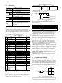
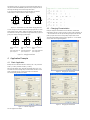
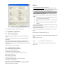
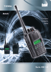
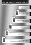
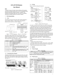
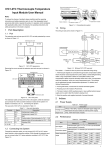
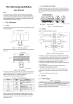
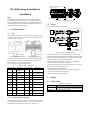
Rem oving extension port cov er before connection IVC1-4DA Analog Output Module User Manual Note: Basic module To reduce the chance of accident, please carefully read the operating instructions and safety precautions prior to use. Only adequately trained personnel shall install or operate this product. In operation, strict compliance with applicable safety rules in the industry, the operating instructions and safety precautions in this book is required. Extension m odule Extens ion cable Figure 1-3 Connecting into system 1.3 Wiring Figure 1-4 shows the wiring of the user port. 1 Port Description 1.1 Port DC/DC Converter DNGP 24Vdc ± 5% 200mA The extension port and user port of IVC1-4DA are both protected by a cover, as shown in Figure 1-1. Removing the covers reveals the extension port and user port, as shown in Figure 1-2. Figure 1-4 Wiring of IVC1-4DA user port The circled 1~7 stands for the seven points to be observed during wiring. Figure 1-1 IVC1-4DA appearance Figure 1-2 IVC1-4DA ports The extension cable connects IVC1-4DA to the system, while the extension port connects IVC1-4DA to another extension module of the system. For details, see section 1.2 Connecting Into System. The user port of IVC1-4DA is described in Table 1-1. Table 1-1 Terminal Name Description Description 1 Analog power 24V+ supply 24V+ 11 I2+ 2 24V- Analog power supply 24V- 12 VI2- Common GND of CH2 V3+ Voltage output of CH3 Current output of CH2 3 · NC 13 4 PG GND 14 · NC 5 Voltage output of V1+ CH1 15 I3+ Current output of CH3 6 · NC 16 VI3- Common GND of CH3 7 I1+ Current output of CH1 17 V4+ Voltage output of CH4 8 Common GND of VI1CH1 18 · NC 9 V2+ Voltage output of CH2 19 I4+ Current output of CH4 10 · NC 20 VI4- Common GND of CH4 1.2 2. Each load of the PLC should be grounded separately. 3. If voltage fluctuation or EMI is present at the output, it is advisable to connect a smoothing capacitor (0.1µF~0.47µF/25V) 4. IVC1-4DA may be damaged if the voltage output is shorted, or if a current load is connected to a voltage output terminal. User port description Terminal Name 1. It is recommended to use shielded twisted pair as the analog output cable. Route them separate from power cables or any cable that may generate EMI. 5. Properly ground the module PG terminal. 6. The 24Vdc power from basic module or any qualified external power supply can be used as the module power source. 7. Do not use the NC terminals of the user port. 2 Indices 2.1 Power Supply Table 2-1 Connecting Into System Through the extension cable, you can connect IVC1-4AD to IVC1 series PLC basic module or other extension module. You can also connect another IVC1 series extension module through the extension port. See Figure 1-3. Item Power supply Description Analog circuit 24Vdc (-15%~+20%), maximum allowable ripple voltage 5%, 120mA (from basic module or external power supply) Digital circuit 5Vdc 50 mA (from basic module) Table 2.2 Performance Table 2-2 Performance Item Specification Occupied I/O points None Conversion speed 2ms/channel (changing channel number will not change conversion speed) Analog output -10 ~ +10Vdc (external load impedence ≥ 2kΩ) Current 0 ~ 20mA (external load impedence: 200Ω ~ 520Ω) OFF (0) b1 or b2 is ON No error b2: power failure 24Vdc power supply failure Power supply normal # 650 0 x × × 4 × 3 2 × 1 Output mode for CH1 Voltage 5mV Output mode for CH3 Current 10A Output mode for CH4 Output mode for CH2 Figure 2-1 ±1% of full range Between analog circuit and digital circuit: PhotoCoupler. Between analog circuit and external power supply: DC/DC converter. Between analog channels: none Isolation Table 2-3 describes the contents of the BFM of IVC1-4DA. Table 2-3 BFM contents Contents Default Property Mode setting element vs. channel The exact correspondence between BFM#650 value and output mode is shown in Table 2-5. Table 2-5 BFM#650 value vs. output mode Value of X Buffer Memory IVC1-4DA exchanges data with the basic module through Buffer Memory (BFM). After IVC1-4DA is set through the host software, the basic module will write data into IVC1-4DA BFM to set the state of IVC1-4TC, and display the data from IVC1-4DA on the host software interface. See figures 4-1 ~ 4-4. BFM ON (1) b0: error Default:-2000 ~ +2000 Setting range:-10,000 ~ +10,000 Accurary 2.3 BFM#300 status information 4. BFM#650: output mode selection, used to set the output modes of CH1 ~ CH4. See Figure 2-1 for their correspondence. Voltage Digital input Resoultion 2-4 Bit status of BFM#300 Mode 0 -10V ~ +10V voltage output 1 0 ~ 20mA current output 2 4 ~ 20mA current output 3 Reserved Note: When the output mode is set as 2, the corresponding channel output characteristic setting D0 (explained in the following note 5) will change automatically, and maintain that value when this channel is set to other modes later. In that case, you need to change D0 as per actual needs. See the following note 5 and section 3 Characteristic Setting for details. #000 CH1 output data RW 5. BFM#900 ~ BFM#915: channel output characteristic setting. Use two points to set the channel characteristic. D0 and D1 stands for digital output, #001 CH2 output data RW while A0 and A1 stands for actual output, in the unit of mV or µA. Each #002 CH3 output data RW #003 CH4 output data RW #300 Module error state word R #650 Channel mode word Default: 0x0000 RW #900 CH1-D0 Default: 0 (output mode 0) RW #901 CH1-A0 Default: 0 (output mode 0) R #902 CH1-D1 Default: 2000 (output mode 0) #903 CH1-A1 Default: 10000 (output mode 0) #904 CH2-D0 Default: 0 (output mode 0) #905 CH2-A0 Default: 0 (output mode 0) #906 CH2-D1 Default: 2000 (output mode 0) #907 CH2-A1 Default: 10000 (output mode 0) #908 CH3-D0 Default: 0 (output mode 0) RW #909 CH3-A0 Default: 0 (output mode 0) R #910 CH3-D1 Default: 2000 (output mode 0) #911 CH3-A1 Default: 10000 (output mode 0) #912 CH4-D0 Default: 0 (output mode 0) RW #913 CH4-A0 Default: 0 (output mode 0) R #914 CH4-D1 Default: 2000 (output mode 0) #915 CH4-A1 Default: 10000 (output mode 0) RW R RW R RW R R RW R RW #4000 Low word of module use Default: 0 time R #4001 High word of module use Default: 0 time R #4094 Module software version 0x1000 information R 0x2400 6. BFM#2100: channel resetting command. When the PLC is in STOP mode, the last output values in its RUN state will be hold. To reset those values into deviation, you can write the hexadecimal number HX4X3 X2X1 into BFM#2100, where X1 is the setting for CH1, X2 is for CH2, and so on. When X is 0, the output will be hold. When X is 1, the output will be reset to the deviation. 7. BFM#4094: module software version information, displayed automatically as Module Version in IVC1-4DA Configuration dialogue box of the host software, as shown in Figure 4-2. 8. BFM#4095: module ID. The ID of IVC1-4DA is 0x2401. The PLC user program can sue this code to identify the module before transceiving data. RW #2100 Channel reset command Default: 0x0000 #4095 Module ID channel occupies four words. To simplify the operation process without affecting functions, A0 and A1 are respectively fixed to analog 0 and the maximum value. When BFM#600 (channel mode) is changed, A0 and A1 will change accordingly. Users cannot change their values. 3 Characteristic Setting The input channel characteristic of IVC1-4DA is the linear relationship between the channel’s digital output D and analog output A. It can be set by the user. Each channel can be considered as the model shown in Figure 3-1. As it is of linear characteristic, the channel characteristic can be defined by just two points: P0 (A0, D0) and P1 (A1, D1), where D0 is the channel’s digital input corresponding to analog output A0, and D1 is the channel’s digital input corresponding to analog output A1. A R Note: 1. CH1 stands for channel 1; CH2, channel 2; CH3, channel 3, and so on. P1 A1 D Digital input Channel D0 P0 A0 D1 D Channel model 2. Property explanation: R means read only. An R element cannot be written. RW means read and write. Reading from a non-existent element will get 0. 3. Table 2-4 shows the BFM#300 status information. A Analog output Channel characteristic Figure 3-1 IVC1-4DA characteristic setting To simplify the operation process without affecting functions, A0 and A1 are respectively fixed to analog 0 and the maximum value in the present mode. That means in Figure 3-1, the A0 is 0, A1 is the maximum analog output in the present mode. When BFM#600 (channel mode) is changed, A0 and A1 will change accordingly. Users cannot change their values. If you set the channel mode without changing D0 and D1, the channel characteristics vs. modes should be as shown in Figure 3-2. A ( mV) 10000 A ( uA ) 20000 D D - 2000 0 2000 A ( uA ) 20000 - 2000 0 2000 4000 - 500 0 - 2000 D 2000 - 10000 A. Mode 0: -10V ~ 10V (default) Figure 3-2 C. Mode 2: 4-20mA B. Mode 1: 0 ~ 20mA Characteristics vs. modes without changing D0 and D1 You can change the channel characteristics by changing D0 and D1, whose setting ranges are both -10000 ~ 10000. If the setting is outside this range, IVC1-4DA will not accept it, but maintain the original valid setting. Figure 3-3 gives you an example of changing characteristics. A ( mV) 10000 A ( uA) 20000 10000 D - 10000 0 10000 -2000 0 A ( uA ) 20000 D 2000 4000 - 10000 - 2500 0 4.2 Changing Characteristics Example: Change the characteristics of IVC1-4DA CH1, CH2 and CH3 respectively as per the A, B and C in Figure 3-3. CH1 (mode 0) outputs a -2V ~ +2V saw-tooth wave, with the step time being the system scan time. CH2 (mode 1) outputs 15mA current. CH3 (mode 2) outputs 4.8mA current. The channel characteristic setting is shown in figures 4-2 ~ 4-4. For details, see IVC Series PLC Programming Manual. D 10000 - 10000 A Mode 0, D0 = 0, D1 = 10,000 Input 10,000 outputs 10V Input 0 outputs 0 V Input -10,000 outputs -10V B Mode 1, D0 = -2000, D1 = 2000 Input 2000 outputs 20mA Input 0 outputs 10mA Input -2000 outputs 0mA Figure 3-3 4 4.1 C Mode 2, D0 = -2500, D1 = 10000 Input 10,000 outputs 20mA Input 0 outputs 4mA Input -2500 outputs 0mA Changing characteristics Application Example Basic Application Example: Set IVC1-4DA CH1 and CH2 to mode 0 (-10V ~ 10V), set CH3 to mode 1 (0 ~ 20mA), and CH4 to mode 2 (4 ~ 20mA). Set as per the following: CH1: saw-tooth wave voltage output -10V ~ 10V, use variant D1. CH2: 5V voltage output, use variant D2; CH3: 5mA current output, use variant D3; CH4: 7.2mA current output, use variant D4. Figure 4-2 Changing CH1 characteristic Figure 4-3 Changing CH2 characteristic The channel setting interface is as follows: Figure 4-1 The user program is as follows: Channel configuration Notice 1. The warranty range is confined to the PLC only. 2. Warranty period is 18 months, within which period INVT Auto-control Technology Co. Ltd. conducts free maintenance and repairing to the PLC that has any fault or damage under the normal operation conditions. 3. The start time of warranty period is the delivery date of the product, of which the product SN is the sole basis of judgment. PLC without a product SN shall be regarded as out of warranty. 4. Even within 18 months, maintenance will also be charged in the following situations: Damages incurred to the PLC due to mis-operations, which are not in compliance with the User Manual; Damages incurred to the PLC due to fire, flood, abnormal voltage, etc; Damages incurred to the PLC due to the improper use of PLC functions. 5. The service fee will be charged according to the actual costs. If there is any contract, the contract prevails. Figure 4-4 Changing CH3 characteristic The user program is the same as the preceding example. 5 6. Please keep this paper and show this paper to the maintenance unit when the product needs to be repaired. 7. If you have any question, please contact the distributor or our company directly. Operation Inspection Shenzhen INVT Auto-control Technology Co., Ltd. 5.1 Routine Inspection 1. Check that the wiring of analog output meets the requirements (see 1.3 wiring). 2. Check that the extension cable of IVC1-4DA is properly inserted in the Address: Gaofa Industry Park, Longjing ,Nanshan District 518055, Shenzhen China Homepage: www.invt.com.cn extension port. 3. Check that the 5V and 24V power supplies are not overloaded. Note: The digital circuit is powered by the basic module through extension cable. 4. Check the application and make sure the operation method and parameter range are correct. 5. Set the IVC1 basic module to RUN state. 5.2 Inspection Upon Fault In case of abnormality, check the following items: ● The status of the POWER indicator ON: the extension cable is properly connected OFF: Check the extension cable connection and the basic module. ● The wiring of analog input ● The status of the 24V indicator ON: 24Vdc power supply normal OFF: 24Vdc power supply possibly faulty, or IVC1-4DA faulty ● The status of the RUN indicator Flash quickly: IVC1-4DA in normal operation Flash slowly or OFF: Check the Error Status in IVC1-4DA Configuration dialogue box through the host software. Version V1.0 Revision date September 28, 2011 All rights reserved. The contents in this document are subject to change without notice.