1
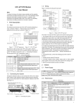
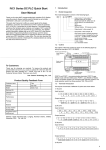
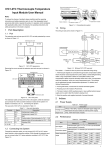
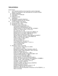
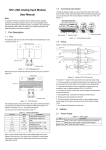
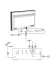
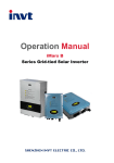
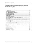
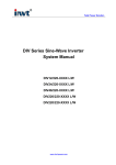
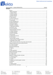
IVC1 Series PLC Passive I/O Extension Module User Manual Please allow us to congratulate you on choosing an INVT Auto-control Technology programmable logic controller (PLC). Before using the IVC1 series PLC product, please carefully read this book so as to fully understand its characteristics, use it safely and bring its functions into full play. Note: To reduce the chance of accident, please carefully read the operating instructions and safety precautions prior to use. Only adequately trained personnel shall install or operate this product. In operation, strict compliance with applicable safety rules in the industry, the operating instructions and safety precautions in this book is required. 1 Introduction 1.1 Appearance And Structure 1.3 Terminal Introduction IVC1-0808ENR, IVC1-0808ENT Pin Function S/S Input mode selection: sink mode when connected with +24V, or source mode when connected with COM Null, for isolation. Leave it suspended X0 ~ X7 Digital input, work with COM to generate input signal Y0 ~ Y7, COM0 Digital output IVC1-0800ENN Pin Function S/S Input mode selection: sink mode when connected with +24V, or source mode when connected with COM Null, for isolation. Leave it suspended X0 ~ X7 Digital input, work with COM to generate input signal IVC1-0008ENR, IVC1-0008ENT The appearance and structure of I/O extension module are shown in the following figure. Extension port cover Pin Y0 ~ Y7, COM0 Function Null, for isolation. Leave it suspended Digital output Connecting terminal cover IVC1-0016ENR, IVC1-0016ENT Pin Extension cable plug Extension cable Product label Status indicator Function ● Null, for isolation. Leave it suspended Y0 ~ Y7, COM0 Y10 ~ Y17, COM1 Control output terminal IVC1-01600ENN Connecting terminal Pin Extension port DIN clip Figure 1-1 Appearance and structure Function S/S Input mode selection: sink mode when connected with +24V, or source mode when connected with COM ● Null, for isolation. Leave it suspended X0 ~ X7, X10 ~ X17 Digital input, work with COM to generate input signal 1.2 Model Designation The model designation is shown in the following figure. 2 Power Supply Table 2-1 I/O extension module type and configuration Type Output type IVC1-0800ENN - 8/0 - IVC1-0808ENR - 8/8 Relay Transistor IVC1-0808ENT - 8/8 IVC1-0008ENR - 0/8 Relay IVC1-0008ENT - 0/8 Transistor IVC1-1600ENN - 16/0 / 0/16 Relay 0/16 Transistor IVC1-0016ENR IVC1-0016ENT Figure 1-2 Model designation Power supply Number of I/O voltage Vac channels Table 2-2 I/O extension module insulation specifications Logic circuit work power from extension cable External wiring To basic module User output (relay) to extension bus Capable of standing one minute of 2830Vac (50Hz) or RMS current with no breakdown or flashover. Leakage current ≤5mA User input to user output (relay) Capable of standing one minute of 2830Vac (50Hz) or RMS current with no breakdown or flashover. Leakage current ≤5mA User input terminal and extension bus Designed by following the SELV circuit requirements To basic module +24V Extension module internal equivalent circuit 24V/5V/GND S/S COM Logic processing circuit Test condition X0 Input devices Name X1 Sensor X2 Xn Table 2-3 I/O extension module power requirement Model 5Vdc/GND 24Vdc/GND 24Vdc/COM IVC1-0800ENN 85mA 0 50mA IVC1-0808ENR 70mA 50mA 50mA IVC1-0808ENT 170mA 0 50mA IVC1-0008ENR 70mA 50mA 0 IVC1-0008ENT 170mA 0 0 IVC1-1600ENN IVC1-0016ENR IVC1-0016ENT 85mA 70mA 170mA 0 50mA 0 50mA 0 0 Note: 1. 5Vdc/GND: working power for logic circuit of extension module, provided by the extension bus 2. 24Vdc/COM: input state detection power, through S/S terminal 3. 24Vdc/GND: working power for relay circuit of extension module, provided by the extension bus Before connecting the extension module to the basic module, calculate the total current of all extension module circuits. Make sure that the currents are smaller than the capacity of the corresponding power supply at the basic module to avoid overloading the basic module. 3 3.1 Input Features IntENRal Equivalent Input Circuit The extension module needs external power supply (+24Vdc) for detecting user switch status. The internal equivalent resistance of the input circuit is about 4.3kΩ, and bi-directional photo coupler is used for signal detection. You can use either sink mode or source mode, so long as dry contact digital signal is input. To connect to the output of active transistor sensor, you need to use the open collector output mode. The wiring of I/O extension module internal equivalent power and inputs is the same as those of the basic module, as shown in Figure 3-1. Figure 3-1 IntENRal equivalent input circuit 3.2 I/O Signal State Indicator The input status indicator displays the status of input terminal. The indicator turns on when the input is in the ON state. Otherwise, the indicator is off. The output status indicator displays the status of output terminal. The indicator turns on when the output is in the ON state (Yn is connected with COMn). Otherwise, the indicator is off. See Figure 3-2. Input status indicator Power indicator Output status indicator Figure 3-2 Status indicator 4 Output Features 4.1 Relay Output Electric Specifications Table 4-1 Relay output terminal electric specifications Item Relay output terminal ExtENRal power Below 250Vac, 30Vdc Circuit isolation By relay Operation indication Relay output contacts closed, LED on Leakage current of open circuit - Min. load 2mA/5Vdc Max. output current Resistive load 2A/1 point, total current of 8 points (sharing one COM) < 8A Inductive load 220Vac, 80VA Illumination 220Vac, 100W Response time OFF→ON Max.: 20ms ON→OFF Max.: 20ms 4.2 Transistor Output Electric Specifications Table 4-2 Transistor output electric specifications Item Transistor output terminal External power 5 ~ 24Vdc Circuit isolation Photo coupler Item Transistor output terminal Operation indication LED is on when photo coupler is driven Leakage current of open circuit < 0.1mA/30Vdc Min. load 5mA (5 ~ 24Vdc) Max. output current 3A/1 point 8A/4 points 1.6A/8 points Above 8 points, total current increases 0.1A at each point increase Respon se time 4.3 Resistive load Inductive load 24Vdc, 7.2W Illumination 24Vdc, 1.5W OFF→ON Max. 0.5ms (100mA/24Vdc) ON→OFF Max. 0.5ms (100mA/24Vdc) Output Connection Example Connecting an IVC1-0808ENR to an IVC1-1614MAR is shown in Figure 4-1. Different output groups can be connected to different signal voltage circuits. For example, output group Y0-COM0 can be connected to the 24Vdc circuit, powered by the local 24V/COM; Y1-COM1, to the 5Vdc circuit; others, like Y2 ~ Y7, to the 220Vac circuit. That is, different output groups can work at circuits of different voltages. 5.2 Extension Module Addressing IVC1 series PLC can identify the connected extension module and address them by connection order automatically. The extension module address is set upon the first power on and remains unchanged. Therefore do not insert or remove the extension module during operation, otherwise abnormalities may occur, or PLC may be damaged. The addresses of I/O channels are in the octal system, numbered as 0, 1, . . . , 7, 10, 11 and so on, without numbers 8 and 9. The input terminals of all modules (basic and extension) are numbered as X0, X1, X2, …X7, X10, X11 and so on, while the output terminals are numbered as Y0, Y1, Y2, …Y7, Y10, Y11 and so on. Every eight channels form one group. If the remaining channels are less than 8, the unused numbers will be left unassigned. For example, in module IVC1-1410MAR, its 14 input channels are numbered asX0 ~ X15, there will be no channels numbered as X16 or X17, because the input channels of the next extension module will start from X20. Likewise, if the module has 10 output channels that are numbered as Y0 ~ Y11, there will be no channels numbered as Y12 ~ Y17, because the output channels of the next extension module will start from Y20. The extension modules’ I/O channels are numbered in accordance with the module’s connection order. See the following for a numbering example. 6 Installation 5 Extension Connection 5.1 Extension Bus Connection Before power-on, remove the cover of the extension port at the right of the basic module. Insert the bus plug into the extension port. If there are more than one extension modules, connect them one by one. Note that the extension port cover is detachable. Do not have it lost. 6.1 Sizes There are eight I/O extension module models: IVC1-0800ENN, IVC1-0808ENR, IVC1-0808ENT, IVC1-0008ENR, IVC1-0008ENT, IVC1-1600ENN, IVC1-0016ENR and IVC1-0016ENT. Their sizes and installation holes are shown in Figure 6-1. 71.2 81 Remove extension port cover before connection 61 4.5 90 Figure 4-1 Connecting IVC1-1614MAR & IVC1-0808ENR Figure 6-1 I/O extension module sizes and installation holes Extension cable Extension cable Figure 5-1 Cascade connection of extension module 6.2 Installation Method The installation method of extension module is the same as that of the basic module. See IVC PLC User Manual for details. See Figure 6-2 for the installation diagram. Figure 6-2 DIN rail mounting Notice 1. The warranty range is confined to the PLC only. 2. Warranty period is 18 months, within which period INVT Auto-control Technology Co. Ltd. conducts free maintenance and repairing to the PLC that has any fault or damage under the normal operation conditions. 3. The start time of warranty period is the delivery date of the product, of which the product SN is the sole basis of judgment. PLC without a product SN shall be regarded as out of warranty. 4. Even within 18 months, maintenance will also be charged in the following situations: Damages incurred to the PLC due to mis-operations, which are not in compliance with the User Manual; Damages incurred to the PLC due to fire, flood, abnormal voltage, etc; Damages incurred to the PLC due to the improper use of PLC functions. 5. The service fee will be charged according to the actual costs. If there is any contract, the contract prevails. 6. Please keep this paper and show this paper to the maintenance unit when the product needs to be repaired. 7. If you have any question, please contact the distributor or our company directly. Shenzhen INVT Auto-control Technology Co., Ltd. Address: Gaofa Industry Park, Longjing ,Nanshan District 518055, Shenzhen China Homepage: www.invt.com.cn Version V1.0 Revision date September 28, 2011 All rights reserved. The contents in this document are subject to change without notice.