1
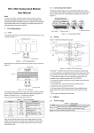
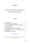
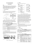
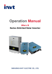
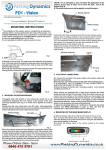
Rem oving extension port cover
before connection
IVC1-2TC Thermocouple Temperature
Input Module User Manual
Note:
To reduce the chance of accident, please carefully read the operating
instructions and safety precautions prior to use. Only adequately trained
personnel shall install or operate this product. In operation, strict compliance
with applicable safety rules in the industry, the operating instructions and
safety precautions in this book is required.
1
Port Description
Basic module
Extension m odule
Extension cable
Figure 1-3 Connecting into system
1.3 Wiring
The wiring of user port is shown in Figure 1-4.
1.1 Port
100Ω
L2+
L2⑤ FG
The extension port and user port of IVC1-2TC are both protected by a cover,
as shown in Figure 1-1.
100Ω
CH2
24V
RUN
POWER
Extension port cover
IVC1-2TC
Thermocouple
100Ω
L1+
L1FG
①
100Ω
CH1
⑥
②
User port cover
DC24V± 10%
50mA
④
Extension cable
PGND
③
24V+
24V-
DC/DC
converter
+5V
AGND
-5V
IVC1-2TC
Figure 1-1 IVC1-2TC appearance
Removing the covers reveals the extension port and user port, as shown in
Figure 1-2.
24V
POWER
User port
14
RUN
Extension port
2
13
2
4
1
3
24V-
24V+
6
5
8
7
10
9
12
11
14
13
16
15
18
17
20
19
FG FG FG FG
L1+ L1- L2+ L2-
IVC1-2TC
Figure 1-4 Wiring of IVC1-2TC user port
The circled 1 ~ 5 stands for the six points to be observed during wiring:
1. Thermocouple signals are connected through screen compensation cables,
which should be routed separate from power cables or other EMI-generating
cables. Long compensation cables are susceptible to EMI, so the
compensation cables should be advisably shorter than 100m. Compensation
cable has impedance, which can cause measurement error. This problem
can be addressed through characteristics adjustment. For details, see 3
Setting Characteristics.
2. If strong EMI exists, connect the FG and PG terminals together.
3. Properly ground the module’s PG terminal.
4. The basic module’s 24Vdc auxiliary power or any qualified external power
supply can be used to feed the module’s analog circuit.
Extension cable
Figure 1-2 IVC1-2TC ports
The extension cable connects IVC1-2TC to the system, while the extension
port connects IVC1-2TC to another extension module of the system. For
details on connection, see 1.2 Connecting Into System.
The user port of IVC1-2TC is described in Table 1-1.
Terminal
1
2
Table 1-1 User port description
Name
Description
24V+
Analog power supply 24V+
24VAnalog power supply 24V-
4
GND
5, 9
7, 11
6, 8, 10, 12
L1+, L2+
L1-, L2FG
Positive poles of thermalcouples for CH1 ~ CH2
Negative poles of thermalcouples for CH1 ~ CH2
Shielding GND
3, 13~20
·
NC
1.2 Connecting Into System
Through the extension cable, you can connect IVC1-2TC to IVC1 series
basic module or other extension modules. While through the extension port,
you can connect other IVC1 series extension modules to IVC1-2TC. See
Figure 1-3.
5. Short the positive and negative terminals of unused channels.
2
Indices
2.1 Power Supply
Table 2-1 Power supply
Description
24Vdc (-15%~20%), maximum allowable ripple voltage: 5%,
Analoge circuit
50mA (from the basic module or external power supply)
Digital circuit
5Vdc, 72mA (from basic module)
Item
2.2 Performance
Table 2-2 Performance
Index
Item
Celsius(°C)
Fahrenheit (°F)
Thermocouple: type K, J, E, N, T, R or S (all accessible
Input signal
to each channel), 2 channels
(240ms±2%)ms × 2 channels (no conversion for unused
Conversion speed
channels)
Rated temperature Type K -100°C~1200°C Type K -148°F ~ +2192°F
range
Type J -100°C~1000°C Type J -148°F ~ +1832°F
Type E -100°C~1000°C Type E -148°F ~ +1832°F
Type N -100°C~1200°C Type N -148°F ~ +2192°F
Type T -200°C ~ +400°C Type T -328°F ~ +752°F
Type R 0°C ~ 1600°C
Type R 32°F ~ 2912°F
1
Item
Digital output
Lowest resolution
Lowest resolution
Accuracy
Isolation
Index
Celsius(°C)
Type S 0°C ~ 1600°C
Fahrenheit (°F)
Type S 32°F ~ 2912°F
12-digit AD conversion, 16-digit complement for storage
Type K -1000 ~ +12000 Type K -1480 ~ +21920
Type J -1000 ~ +10000 Type J -1480 ~ +18320
Type E -1000 ~ +10000 Type E -1480 ~ +18320
Type N -1000 ~ +12000 Type N -1480 ~ +21920
Type T -2000 ~ +4000
Type T -3280 ~ +7520
Type R 0 ~ 16000
Type R 320 ~ 29120
Type S 320 ~ 29120
Type S 0 ~ 16000
Type K 0.3°C
Type K 0.54°F
Type J 0.2°C
Type J 0.36°F
Type E 0.3°C
Type E 0.54°F
Type N 0.3°C
Type N 0.54°F
Type T 0.2°C
Type T 0.36°F
Type R 0.5°C
Type R 0.9°F
Type S 0.5°C
Type S 0.9°F
± (0.5% full range+1°C), water freezing point: 0°C/32°F
Between analog circuit and digital circuit: photocoupler.
Between analog circuit and input 24Vdc power: internal
isolation. Between analog channels: none
Table 2-4 BFM#300 status information
Bit status of BFM#300
ON (1)
OFF (0)
b1 or b2 is ON, AD conversion
No error
b0: error
of all channels stopped
b2: power failure
24Vdc power supply failed
Power supply normal
AD converter or other
b3: hardware fault
Hardware normal
hardware faulty
Digital output after AD
b10: digital range error conversion outside the range Digital output normal
of -2048 ~ 2047
b12 ~ b15: reserved
5. BFM#301 error status information is shown in Table 2-5.
Channel
1
2
Table 2-5 BFM#301 status information
ON (1)
CH1 temperature lower than lower limit
CH1 temperature higher than upper limit
CH2 temperature lower than lower limit
CH2 temperature higher than upper limit
b4 ~ b15
Bit
b0
b1
b2
b3
Reserved
6. BFM#600: channel mode selection, used to set the working modes of CH1
~ CH2. See Figure 2-1 for their correspondence.
# 600
2.3 Buffer Memory
0x
×4
×3
×1
Working mode for CH2
Reserved
Reserved
Figure 2-1 Mode setting element vs. channel
Table 2-3 describes the contents of the BFM of IVC1-2TC.
Property
The exact meaning of the X in the channel mode is shown in Table 2-6. The
conversion time of every channel is 240ms. When a channel is set closed, it
will not perform AD conversion, thereby reducing the total conversion time.
R
R
R
R
RW
RW
RW
RW
RW
RW
RW
RW
RW
RW
R
R
R
Note:
1. CH1 stands for channel 1; CH2, channel 2.
2. Property explanation: R means read only. An R element cannot be written.
RW means read and write. Reading from a non-existent element will get 0.
3. BFM#200 ~ BFM#201: current temperature. Unit: 0.1°C/°F (determined by
BFM#600). The average value are stored in BFM#100-BFM#101.
4. BFM#300 error status information is shown in Table 2-4.
×2
Working mode for CH1
IVC1-2TC exchanges data with the basic module through Buffer Memory
(BFM). After IVC1-2TC is set through the host software, the basic module will
write data into IVC1-2TC BFM to set the state of IVC1-2TC, and display the
data from IVC1-2TC on the host software interface. See figures 4-1 ~ 4-8.
Table 2-3 BFM contents
BFM
Content
Default
Average temperature of
#100 ~ #101
CH1~CH2
Current temperature of
#200 ~ #201
CH1~CH2
#300
Error status word 0
#301
Error status word 1
#600
Channel mode word
0x0000
Sampling times respectively
#700 ~ #701
8
for averages of CH1 ~ CH2
#900
CH1-D0
0 (input mode 0)
#901
CH1-A0
0 (input mode 0)
#902
CH1-D1
12000 (input mode 0)
#903
CH1-A1
12000 (input mode 0)
#904
CH2-D0
0 (input mode 0)
#905
CH2-A0
0 (input mode 0)
#906
CH2-D1
12000 (input mode 0)
#907
CH2-A1
12000 (input mode 0)
#3000
Cold junction temperature For test
#4094
Module software version
0x1000
#4095
Module ID
0x4021
OFF (0)
CH1 normal
CH1 normal
CH2 normal
CH2 normal
No.
1
2
3
4
5
6
7
8
9
10
11
12
13
14
15
16
Table 2-6 Meaning of X in channel mode
X (hexadecimal)
Meaning
0
K type thermocouple. Digital signal unit: 0.1°C
1
K type thermocouple. Digital signal unit: 0.1°F
2
J type thermocouple. Digital signal unit: 0.1°C
3
J type thermocouple. Digital signal unit: 0.1°F
4
E type thermocouple. Digital signal unit: 0.1°C
5
E type thermocouple. Digital signal unit: 0.1°F
6
N type thermocouple. Digital signal unit: 0.1°C
7
N type thermocouple. Digital signal unit: 0.1°F
8
T type thermocouple. Digital signal unit: 0.1°C
9
T type thermocouple. Digital signal unit: 0.1°F
A
R type thermocouple. Digital signal unit: 0.1°C
B
R type thermocouple. Digital signal unit: 0.1°F
C
S type thermocouple. Digital signal unit: 0.1°C
D
S type thermocouple. Digital signal unit: 0.1°F
E
Channel closed
F
Channel closed
7. BFM#700 ~ BFM#701: average sampling times setting. Range: 1 ~ 256. If
the setting is outside this range, the value will be reset to the default 8.
5. BFM#900 ~ BFM#907: channel characteristics setting data register. Use
two points to define the channel characteristic. D0 and D1 are the channel
digital output, in the unit of 0.1°C. A0 and A1 are the actual temperature input
of the channel, also in the unit of 0.1°C. Each channel occupies 4 words.
You can change the channel characteristic by changing D0 and D1. The
setting range of D0 is -1000~1000 (0.1°C); D1, 11,000~13,000 (0.1°C). If the
setting is outside this range, IVC1-2TC will not accept it, but maintain the
original valid setting.
Note that the characters are all in 0.1°C unit. Convert Fahrenheit parameters
as per the following formula before using them in the characteristic setting:
Celsius = 5/9 × (Fahrenheit - 32)
9. BFM#4094: software version information, displayed automatically as
Module Version in IVC1-2TC Configuration dialogue box of the host
software, as shown in Figure 4-1.
10. BFM#4095: module ID. The ID of IVC1-2TC is 0x4021. The PLC user
2
5
Figure 4-4 Changing CH2 characteristic
Operation Inspection
Technology Co. Ltd. conducts free maintenance and repairing to the PLC that
has any fault or damage under the normal operation conditions.
3. The start time of warranty period is the delivery date of the product, of
which the product SN is the sole basis of judgment. PLC without a product
SN shall be regarded as out of warranty.
4. Even within 18 months, maintenance will also be charged in the following
situations:
Damages incurred to the PLC due to mis-operations, which are not in
compliance with the User Manual;
Damages incurred to the PLC due to fire, flood, abnormal voltage, etc;
Damages incurred to the PLC due to the improper use of PLC functions.
5. The service fee will be charged according to the actual costs. If there is any
contract, the contract prevails.
6. Please keep this paper and show this paper to the maintenance unit when
the product needs to be repaired.
7. If you have any question, please contact the distributor or our company
directly.
5.1 Routine Inspection
Homepage: www.invt-control.com
3. Check that the 5V and 24V power supplies are not overloaded. Note: The
digital circuit is powered by the basic module through extension cable.
Address: Gaofa Industry Park, Longjing ,Nanshan District 518055, Shenzhen
China
2. Check that the extension cable of IVC1-2TC is properly inserted in the
extension port.
Shenzhen INVT Auto-control Technology Co., Ltd.
1. Check that the wiring of analog input meets the requirements (see 1.3
Wiring).
All rights reserved. The contents in this document are subject to change
without notice.
5.2 Inspection Upon Fault
February 15, 2012
Revision date
5. Set the IVC1 basic module to RUN state.
V1.0
Version
4. Check the application, make sure the operation method and parameter
range are correct.
In case of abnormality, check the following items:
The status of the POWER indicator
ON: the extension cable is properly connected;
OFF: check the extension cable connection and the basic module.
The status of the 24V indicator
The wiring of analog input
ON: 24Vdc power supply normal;
OFF: 24Vdc power supply possibly faulty, or IVC1-2TC faulty.
The status of the RUN indicator
Flash quickly: IVC1-2TC in normal operation;
Flash slowly or OFF: Check the Error Status in IVC1-2TC Configuration
dialogue box through the host software.
Notice
1. The warranty range is confined to the PLC only.
2. Warranty period is 18 months, within which period INVT Auto-control
4
program can use this code to identify the module before transceiving data.
3
Characteristic Setting
click the downward arrow button → to continue to set CH2, whose setting
interfaces are shown in Figure 4-1 ~ Figure 4-2. For detailed software usage,
see IVC Series Small PLC Programming Manual.
The input channel characteristic of IVC1-2TC is the linear relationship
between the channel’s analog input A and digital output D. It can be set by
the user. Each channel can be considered as the model shown in Figure 3-1.
As it is of linear characteristic, the channel characteristic can be defined by
just two points: P0 (A0, D0) and P1 (A1, D1), where D0 is the channel’s
digital output corresponding to analog input A0, and D1 is the channel’s
digital output corresponding to analog input A1.
D(0.1℃)
P1
D1
A
Analog input
Channel
D
D0
Digital output
P0
A0
Channel model
A(0.1℃)
A1
Figure 4-1 CH1 setting interface
Figure 3-1 IVC1-2TC channel characteristic setting
The channel characteristic setting is used to correct the onsite linear error in
IVC1-2TC measurement caused by the different ambient temperatures and
compensation cables.
To simplify the operation process without affecting functions, A0 and A1 are
respectively fixed to 0 and 12,000 (unit: 0.1°C) in the present mode. That is to
say, the A0 and A1 in Figure 3-1 are respectively 0 and 12,000 (unit: 0.1°C).
Users cannot change their values.
If you just set the channel mode without changing D0 and D1, the channel
characteristic vs. 0 mode should be as shown in Figure 3-2.
D (0.1°
C)
12000
Figure 4-2 CH2 setting interface
A (0.1°
C)
- 1000
0
4.2 Changing Characteristics
12000
- 1000
Default (not adjusted)
Figure 3-2
Characteristic of 0 mode without changing D0 and D1
Example: Connect CH1 of IVC1-2TC to K thermocouple to output Celsius,
connect CH2 to J type thermocouple to output Fahrenheit. Set characteristics
of channels 1 and 2 as per Figure 3-3. Set the average sampling times to 4
and use registers D1 and D2 to receive the average value.
Note that when the mode is set to 1 or 3, the output will be in 0.1°F unit, and
the temperature data read from the output data zone will be in 0.1°F unit. But
the data in the channel characteristic setting zone will still be in 0.1°C unit,
which means the data in the channel characteristic setting zone is always in
0.1°C unit. Keep this in mind when changing D0 and D1.
You can change the characteristics by changing D0 and D1. The setting
range of D0 is -1000~1000 (0.1°C); D1, 11000~13000 (0.1°C). If the setting is
outside this range, IVC1-2TC will not accept it, but maintain the original valid
setting. Figure 3-3 provides you an example of changing K type and J type
thermocouple characteristic when the IVC1-2TC measured value is 5°C
(41°F) higher the actual value.
D (0. 1 °
C )
11950
- 950
P1
A ( 0 .1 °
C)
0
- 50
Figure 4-3 Changing CH1 characteristic
12000
P0
- 1000
D 0 = - 50
D 1 = 11950
Figure 3-3
4
Changing characteristic
Application Example
4.1 Basic Application
Example: Connect CH1 and CH2 of IVC1-2TC respectively to K and J type
thermocouples with Celsius output. Set the average sampling times of CH1
and CH2 to 4, and use data registers D1 ~ D2 to receive the average value.
The setting interface of output CH1 is shown in Figure 4-1. After the setting,
3