1
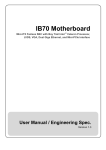
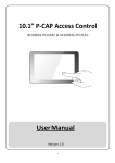
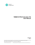
DIN Rail Box PC
Intel Celeron Bay Trail-M
IBDRW / IBDRW-Ex
User Manual
Version 1.0
Contents
CHAPTER 1 WINMATE IBDRW / IBDRW-EX OVERVIEW ............................ 4
1.1
Introduction.................................................................................................4
1.2
Hardware Specification ...............................................................................4
1.2.1
System Specification..............................................................................4
1.2.2
Mechanical and Power...........................................................................4
1.2.3
I/O Connectors.......................................................................................5
1.2.4
Environment Considerations..................................................................5
1.3
Packing List ................................................................................................5
1.4
Safety Precaution .......................................................................................5
1.5
Chassis Dimension.....................................................................................7
CHAPTER 2 HARDWARE FUNCTIONALITY ................................................ 8
2.1
Winmate IBDRW / IBDRW-Ex Peripherals..................................................8
2.1.1
DC Adapter Jack....................................................................................8
2.1.2
DC Adapter Jack....................................................................................8
2.1.3
Panel .....................................................................................................9
2.1.4
DVI Connector .......................................................................................9
2.1.5
Mini PCIe ...............................................................................................9
2.1.6
SSD .....................................................................................................10
2.1.7
USB 2.0 + USB 3.0 + LAN Connector..................................................10
2.1.8
Dual LAN .............................................................................................11
2.1.9
COM + VGA.........................................................................................11
2.1.10 Audio ...................................................................................................12
2.1.11 DIDO ...................................................................................................12
2.1.12 RS422, RS485.....................................................................................12
2.1.13 Isolator DIDO (CON4)..........................................................................13
2.1.14 Clear CMOS ........................................................................................13
2.1.15 RS422, RS485 Terminal Resistor.........................................................13
2.1.16 RS422, RS485.....................................................................................13
2.1.17 RS232, RS422, RS485 ........................................................................14
CHAPTER 3 INITIAL SETUP........................................................................ 15
3.1
DIN Rail Mounting Setup ..........................................................................15
3.2
Cable ARM Bracket Installation (optional for IBDR-Ex) .............................16
3.3
Configuration of the BIOS.........................................................................17
3.3.1
BIOS setup and Boot Procedure..........................................................17
3.3.2
BIOS Setup Keys.................................................................................17
2
3.3.3
MAIN ...................................................................................................18
3.3.4
BIOS Advance Setup Utility..................................................................19
3.3.5
Advanced.............................................................................................20
3.3.6
USB Configuration ...............................................................................21
3.3.7
Chipset ................................................................................................23
3.3.8
Chipset North Bridge Parameters ........................................................23
3.3.9
Chipset South Bridge Parameters........................................................24
3.3.10 Security ...............................................................................................25
3.3.11 Security Boot Menu .............................................................................27
3.3.12 Boot .....................................................................................................28
3.3.13 Save & Exit ..........................................................................................29
APPENDIX.................................................................................................... 31
3
Chapter 1 Winmate IBDRW / IBDRW-Ex Overview
1.1 Introduction
Winmate IBDRW is a DIN-rail mounted Fanless Box PC, which provides several
serial communication ports. With a compact size and small form factor as well as
front accessible I/Os, Winmate IBDR is very convenient for wiring and DIN-rail
installation in the control cabinet. The Wide operation temperature and Industrial
serial port design makes this unit a perfect communication even in harsh and
critical location. While IBDRW-Ex is ATEX and Class 1 Division 2 certified DIN
Rail Box pc for hazardous location deployment and for ATEX certified Box PC
requires special enclosure box.
1.2 Hardware Specification
1.2.1 System Specification
Processor
: Intel ®Celeron ® Bay Trail-M
System Chipset
: Bay Trail SoC Chipset
System Memory
: 1 x DDR3L 1333MHz SO-DIMM 2GB (max 8GB)
Ethernet Controller
: 4 x Intel ®WG82574L GbE LAN
USB
: 1 x USB 3.0
: 3 x USB 2.0 (external)
: 2 x USB 2.0 by pin-header (internal)
Storage
: Default 32GB mSATA SSD
Second Storage (optional) : 2.5” SSD 64~512GB
1.2.2 Mechanical and Power
Dimensions
: 85.5mm x 152mm x 139mm (L x W x H)
Construction
: Aluminum Housing
Power Input
: 9-36V DC IN (isolation)
Power Source Range
: 20W max.
Mounting
: DIN Rail
4
1.2.3 I/O Connectors
Front Side I/O
: 1 x Power ON/OFF button with LED indicator
1 x Line Out, Line In, Mic In
4 x RJ-45 (Giga LAN)
1 x RS232 default (422/485 as optional)
1 x VGA
1 x USB3.0,
3 x USB2.0
1 x DC Power Terminal Block
1 x RS232 default (Isolated RS232/485 as optional)
1 x 20 pins terminal block DIDO
1.2.4 Environment Considerations
Operating Temperature
: -20 to 60 deg. C
Operating Humidity
: 5% to 95% (non condensing)
Anti Vibration
: 5Hz – 500Hz / 1 Grms / 3 Axis
1.3 Packing List
• 1 x DIN Rail Mounting clip
• 1 x User Manual
• 1 x 12V AC to DC Power Adapter with power cord
• 1 x System Recovery DVD (optional)
• Terminal block female connectors
• Cable Arm Bracket (Optional for IBDR-Ex)
1.4 Safety Precaution
WARNING!
Always completely disconnect the power cord from your chassis
whenever you work with the hardware. Do not make connections while
the power is on. Sensitive electronic components can be damaged by
sudden power surges. Only experienced electronics personnel should
open the PC chassis.
5
CAUTION!
Always ground yourself to remove any static charge before touching the
CPU card. Modern electronic devices are very sensitive to static electric
charges. As a safety precaution, use a grounding wrist strap at all times.
Place all electronic components in a static-dissipative surface or
static-shielded bag when they are not in the chassis.
SAFETY PRECAUTIONS!
l
Please read this safety instruction carefully.
l
Place keep this user’s manual for later reference.
l
Please disconnect this equipment for any AC outlet before cleaning. Use
liquid or spray detergents for cleaning. Use a damp cloth.
l
Do not touch the LCD panel surface with sharp or hard objects.
l
For pluggable equipment, the power outlet must be installed near the
equipment and must be easily accessible.
l
Keep this equipment away from humidity.
l
Place this equipment on a reliable surface during installation, dropping letting
it fall could cause damage.
l
The openings on the enclosure are for air convection. Protect the equipment
from overheating. DO NOT COVER THE OPENINGS.
l
Make sure the voltage of the power source is correct before connecting the
equipment to the power outlet.
l
Position the power cord so that people cannot step on it. Do not place
anything over the power cord.
l
All cautions and warnings on the equipment should be noted.
l
If the equipment is not used for a long time, disconnect it from the power
source to avoid damage by transient over-voltage.
l
Never pour any liquid into an opening. This could cause fire or electrical
shock.
l
Never open the equipment. For safety reasons, only qualified service
personnel should open the equipment.
l
If any of the following situations arises, get the equipment check personnel:
n
The power cord or plug is damaged
n
Liquid has penetrated into the equipment
n
The equipment has been exposed to moisture
n
The equipment does not work well, or you cannot get it to work
according to user’s manual
n
The equipment has been dropped and damaged
n
The equipment has obvious signs of breakage
6
l
Do not leave this equipment in an uncontrolled environment where
temperature is below -20oC (-4oF) or above 60oC (140oF). It may damage the
equipment.
l
Caution – Use recommended mounting apparatus to avoid risk of injury.
l
Warning – Only use the connection cords which come along with the product,
when in doubt, please contact the manufacturer.
l
Provision shall be made to provide transient protection device to be set at a
level not exceeding 140% of the rated voltage at the power supply terminals
of the apparatus.
l
Warning – Explosion Hazard – Do not disconnect equipment unless power
has been switched off or the area is known to be non-hazardous.
l
Warning – The equipment should be adequately protected from direct light
when installed indoor or outdoor.
1.5 Chassis Dimension
7
Chapter 2 Hardware Functionality
2.1 Winmate IBDRW / IBDRW-Ex Peripherals
The following figures show the connectors on Winmate IBDRW and the following
sections give you detailed information about function of each peripheral.
2.1.1 DC Adapter Jack
Pin
Signal Name
1
Adapter
2
GND
3
GND
4
GND
5
Adapter_DC
6
Adapter_DC
2.1.2 DC Adapter Jack
Pin
Signal Name
Pin
Signal Name
1
USB5V
12
TX2+
2
USB-
13
TX2-
3
USB+
14
TX3+
4
GND
15
TX3-
5
USB5V
16
TX4+
6
USB-
17
TX4-
7
USB+
18
DGND
8
GND
19
LEDGND
9
NA
20
YLED
10
TX1+
21
OLED
11
TX1-
22
GLED
2.1.3 Panel
Pin
Signal Name
Pin
Signal Name
1
+V5S
6
GND
2
+V3.3S
7
GND
3
GND
8
FP_RST_N
4
SATA_LED#
9
NA
5
PWRBTN#
10
+V5A
Pin
Signal Name
Pin
Signal Name
1
GND
10
GND
2
HDMIB_TMDS0-
11
HDMIB_TMDS2 -
3
HDMIB_TMDS0+
12
HDMIB_TMDS2 +
4
GND
13
GND
5
HDMI_DDC_CLK
14
HDMIB_CLK +
6
HDMI_DDC_DATA
15
HDMIB_CLK -
7
GND
16
HDMI_HPD1
8
HDMIB_TMDS1-
17
+V5S
9
HDMIB_TMDS1+
18
+V5S
2.1.4 DVI Connector
2.1.5 Mini PCIe
9
2.1.6 SSD
2.1.7 USB 2.0 + USB 3.0 + LAN Connector
Pin
Signal Name
Pin
Signal Name
1
+5VUSB3.0
20
LAN1_MDI0_IN+
2
U2DN0
21
LAN1_MDI0_IN-
3
U2DP0
22
LAN1_MDI1_IN+
4
UGND
23
LAN1_MDI1_IN-
5
U3RXDN1
24
LAN1_MDI2_IN+
6
U3RXDP1
25
LAN1_MDI2_IN-
7
UGND
26
LAN1_MDI3_IN+
8
U3TXDN1
27
LAN1_MDI3_IN-
9
U3TXDP1
28
LAN1_DGND
10
+5VUSB3.0
29
LAN1_VDD33
11
U2DN1
30
LAN1_ACTIVE_Y
12
U2DP1
31
LAN1_1000_O
13
UGND
32
LAN1_100_10_G
19
N89607501
10
2.1.8 Dual LAN
Pin
Signal Name
Pin
Signal Name
1
LAN3_MDI0_IN+
19
NA
2
LAN3_MDI0_IN-
20
GND
3
LAN3_MDI1_IN+
21
LAN3_100_10_G
4
LAN3_MDI1_IN-
22
LAN3_1000_O
5
LAN3_MDI2_IN+
23
LAN3_ACTIVE_Y
6
LAN3_MDI2_IN-
24
LAN3_VDD33
7
LAN3_MDI3_IN+
25
LAN4_100_10_G
8
LAN3_MDI3_IN-
26
LAN4_1000_O
9
NA
27
LAN4_ACTIVE_Y
10
GND
28
LAN4_VDD33
11
LAN4_MDI0_IN+
29
LAN_GND
12
LAN4_MDI0_IN-
30
LAN_GND
13
LAN4_MDI1_IN+
31
LAN_GND
14
LAN4_MDI1_IN-
32
NA
15
LAN4_MDI2_IN+
33
LAN_GND
16
LAN4_MDI2_IN-
34
LAN_GND
17
LAN4_MDI3_IN+
35
LAN_GND
18
LAN4_MDI3_IN-
36
NA
2.1.9 COM + VGA
Pin
Signal Name
Pin
Signal Name
C1
DCD4/485TXRX-
V1
R_FILTER
C2
SRD4/485TXRX+
V2
G_FILTER
C3
STD4/422RX+
V3
B_FILTER
C4
DTR4/422RX-
V4
NA
C5
GND
V5
GND
C6
NDSR1
V6
GND
C7
NRTS1
V7
GND
C8
NCTS1
V8
GND
C9
NRI1
V9
VGA_5V
V10
GND
11
2.1.10 Audio
Pin
Signal Name
Pin
Signal Name
A1
Line1_L
C1
MIC1_L
A2
SW_C
C2
SW_B
A3
AUGND
C3
AUGND
A4
LINE1_R
C4
MIC1_R
B1
AZ_FOUT_L
G1
AUGND
B2
LINE2_JD
G2
AUGND
B3
AUGND
G3
AUGND
B4
AZ_FOUT_R
G4
AUGND
C0
AUGND
A1
LINE1_L
A2
SW_C
2.1.11 DIDO
Pin
Signal Name
Pin
Signal Name
1
GND
8
DINT1
2
DIO_5V
9
DINT2
3
DOUT3
10
DINT0
4
DOUT1
11
GPIO53_IN0
5
DOUT2
12
GPIO56_OUT0
6
DOUT0
13
GPIO54_IN1
7
DINT3
14
GPIO57_OUT1
2.1.12 RS422, RS485
Pin
Signal Name
Pin
Signal Name
1
GND
8
DINT1
2
DIO_5V
9
DINT2
3
DOUT3
10
DINT0
4
DOUT1
11
GPIO53_IN0
5
DOUT2
12
GPIO56_OUT0
12
2.1.13 Isolator DIDO (CON4)
Pin
Signal Name
Pin
Signal Name
1
ISO5V
6
DO2_GPIO
2
ISOGND
7
DI3_GPIO
3
DI1_GPIO
8
DO3_GPIO
4
DO1_GPIO
9
DI4_GPIO
5
DI2_GPIO
10
DO4_GPIO
2.1.14 Clear CMOS
1-2 : Clear CMOS
2-3 : Normal
2.1.15 RS422, RS485 Terminal Resistor
1-2 : 120 ohm
2.1.16 RS422, RS485
1-2 : RS485
2-3 : RS422
13
2.1.17 RS232, RS422, RS485
Jumper
RS232
RS422
RS485
JP8 (2x3)
1-2
3-4
5-6
1-2
2-3
2-3
4-5
5-6
5-6
7-8
8-9
8-9
10-11
11-12
11-12
JP9 (3x4)
14
Chapter 3 Initial Setup
3.1 DIN Rail Mounting Setup
Please follow these steps to mount the IBDRW hook kit on a DIN rail
1. Screw the provided DIN-rail Kit on the rear side of the box as the diagram
shown below.
2. Please make sure the stiff metal handle part is located on the top
3. Press the stiff metal handle downward and insert the hook into the DIN-rail
4. Release the handle so it can snap into place as shown below
15
3.2 Cable ARM Bracket Installation (optional for IBDR-Ex)
In hazardous locations, sparks caused by the movement from a cable and
connector which is even slightly loose could lead to a disaster and to prevent this,
cable arm bracket can be use to secure some LAN, USB and Audio connectors.
Follow these steps to complete the installation
1. Find the cable arm bracket in the package, including the plate, bracket / holder,
and screws
2. Install the plate on the top of the box and screw it tightly
3. Plug all the necessary cables into the connectors
4. Place the cable arm bracket according to the picture and then attach the
bracket / holders to the plate and then screw it for securing the installed cables
For ATEX deployment, it is require to have Enclosure box
Note
16
3.3 Configuration of the BIOS
3.3.1 BIOS setup and Boot Procedure
BIOS stands for “Basic Input Output System” and it is the most basic
communication between user and the hardware. To enter BIOS Setup, the
[DEL] key must be pressed after the USB controller has been initialized as
soon as the following message appears on the monitor during Power On Self
Test (POST):
“Press DEL to run SETUP”
Note : Update BIOS version may be published after the manual is released.
Please check with the latest version of BIOS on the website. User may
need to run BIOS setup utility for the following status:
1. Error message on screen indicate to check BIOS Setup
2. Restoring the Factory default setting
3. Modifing the specific hardware specification
4. Want to optimize the specification
3.3.2 BIOS Setup Keys
The following keys are enabled during POST:
Key
Function
Del
Enters the BIOS setup menu
Display the boot menu. Lists all bootable devices that are
F7
connected to the system. With cursor ↑ and cursor ↓ and by
pressing <ENTER>, select the device used for the boot
Pause
Pressing the [Pause] key stops the POST. Press any other key to
resume the POST.
The following keys can be used after entering the BIOS Setup:
Key
Function
F1
General Help
F2
Previous Values
17
F3
Optimized Defaults
F4
Save & Exit
Esc
Exit
+/-
Change Opt.
Enter
Select or execute command
Cursor ↑
Moves to the previous item
Cursor ↓
Goes to the next item
Cursor ←
Moves to the previous item
Cursor →
Goes to the next item
3.3.3 MAIN
Immediately after the [DEL] key is pressed during startup, the main BIOS setup
menu appears:
18
BIOS setting
Description
Setting options
Effect
This is current time
setting. The time is
System Time
maintained by the
battery when the device
Adjustment of the
Set the time in the
time
format [hh:mm:ss]
is turned off
This is current date
setting. The time is
System Date
maintained by the
battery when the device
Changes to the
date
Set the date in the
format
[mm/dd/yyyy]
is turned off
Set the language
System Language
This is current language
Adjustment of the
setting.
language
in other language.
The language in
this device is
English
3.3.4 BIOS Advance Setup Utility
BIOS Setting
Intel AMT Support
Intel AMT Setup Prompt
Description
Enable and disable BIOS support for Intel Active Management
Technology
Enable and disable the boot interruption <Ctrl+P> to call up Intel
Management Engine BIOS Extention (MBEx) configuration page
Enable Client Initiated Remote Access (CIRA) Fast Call for Help.
AMT CIRA Request Trig
CIRA allows AMT maintenance event if the AMT PC is not in the
intranet
AMT CIRA Timeout
Un-Configure ME
USB Configure
CIRA timeout for connection establishment with MPS
(Manageability Presence Server / “vPro Enabled Gateway”)
Resets all the values of the MEBx to their defaults (see section
“Reset with Un-Configure”)
USB Configure:
Enable and disable the USB configuration (provisioning)
19
3.3.5 Advanced
BIOS Setting
Description
Setting
Effect
options
ACPI Settings
Configures ACPI settings
Enter
SMART Settings
Configures SMART settings
Enter
Super IO Configuration
Configures System Super IO
Chip parameters
Enter
Hardware Monitor
Monitor hardware status
Enter
CPU Configuration
Configures CPU settings
Enter
PPM Configuration
Configures PPM Parameters
Enter
Thermal Configuration
IDE Configuration
Configures Thermal
Parameters
Configures IDE devices
20
Enter
Enter
Opens
submenu
Opens
submenu
Opens
submenu
Opens
submenu
Opens
submenu
Opens
submenu
Opens
submenu
Opens
submenu
LPSS & SCC
Configuration
Network Stack
Configuration
Configures LPSS & SCC
Enter
Configures network stack
Enter
Configures CSM:
CSM Configuration
Enable/Disable, Option ROM
Enter
execution settings, etc.
CMOS
CMOS settings / Information
Enter
Trusting Computing
Trusted computing settings
Enter
USB Configuration
Configures USB settings
Enter
Platform Trust Technology
Platform trust technology
Enter
Opens
submenu
Opens
submenu
Opens
submenu
Opens
submenu
Opens
submenu
Opens
submenu
Opens
submenu
3.3.6 USB Configuration
BIOS Setting
Description
Setting
Effect
options
Legacy USB
User can enable or
Disable
21
will keep USB devices
available only for EFI
Support
applications
disable USB port
Enable
User can enable or
USB 3.0 Support
This is a workaround for
OSes without XHCI
hand-off support
This is a workaround for
EHCI Hand-off
OSes without ECHI
hand-off support
USB mass
User can Enable or
storage driver
disable USB mass
support
storage driver support
USB Transfer
time-out
Device Reset
time-out
devices
Enable
USB 3.0 is enable
Disable
USB 3.0 is disable
Disable
Disables this function
Enable
Enables this function
Disable
Disables this function
Enable
Enables this function
Disable
Disables this function
Enable
Enables this function
disable USB 3.0 (XHCI)
controller support.
XHCI Hand-off
Enable all the USB
1 Sec
The time-out value for
control, bulk, and
interrupt transfers
5 Sec
Depends on the time-out
10 Sec
value
20 Sec
10 Sec
USB mass storage
device start unit
command time-out
20 Sec
Depends on the time-out
30 Sec
value
40 Sec
Maximum time the
Device power-up
device will take before it
delay
properly reports itself to
Uses default value: for a
Auto
the host controller
root port it is 100 ms, for a
Hub port the delay is taken
from Hub descriptor
22
3.3.7 Chipset
3.3.8 Chipset North Bridge Parameters
BIOS Setting
Description
Setting
Effect
options
Intel IGD Configuration
Provides onboard
graphics-related
23
Enter
Opens
submenu
configuration options
IGD – LCD Control
Graphic Power
Management Control
Configures IGD – LCD
setting
Enter
Provides power saving
configuration options for the
Enter
onboard graphics
Opens
submenu
Opens
submenu
3.3.9 Chipset South Bridge Parameters
BIOS Setting
Description
Setting
Effect
options
Azalia HD Audio
Configures onboard audio
Disable
function
Enable
USB Configuration
Provides user with
configuration options for the
USB 2.0(EHCI)
USB controller, such as
enabling/disabling a
USB Port 0
specific USB port and
support for certain features
USB Port 1
USB Port 2
24
Disables this
function
Enables this
function
Enable / Disable
this function
Enable / Disable
this function
Enable / Disable
this function
Enable / Disable
this function
USB Port 3
Provides user with
configuration options for the
PCI Express
Configuration
PCI Express bus, such as
enabling/disabling
a specific PCI Express
channel and speed
configuration
Configures high precision
High Precision Timer
this function
PCI Express
Enable / Disable
port 0
this function
PCI Express
Enable / Disable
port 1
this function
PCI Express
Enable / Disable
port 2
this function
PCI Express
Enable / Disable
port 3
this function
Disable
timer (HPET) in the
operating system
Enable / Disable
Enable
Disables this
function
Enables this
function
The System
Power Off
stays off upon
the return of the
AC power
The System is
Configures the state of the
Restore AC Power Loss
Power On
system after return of power
turned on upon
the return of the
AC power
on AC power loss
The system
returns to its last
Last State
known awake
state upon the
return of the AC
power
Quite
Serial IRQ Mode
Configures IRQ mode
Entering quite
(active) mode
Entering
Continuous
Continuous
(idle) mode
3.3.10 Security
Allows user to configure an administration or user password, user must enter the
administrator or user password at system startup and when entering BIOS setup
25
BIOS Setting
Description
Setting
Effect
options
Displays whether or not an
Administrator Password
administrator password has
Enter
Enter Password
Enter
Enter Password
been set
User Password
Display whether or not a
user password has been set
26
3.3.11 Security Boot Menu
BIOS Setting
Secure Boot
Description
Setting options
Displays the current boot
Disable
state
Enable
Secure Boot Mode
Allows user to configure
Disable
the secure boot mode
Enable
Effect
Disables this
function
Enables this
function
Disables this
function
Enables this
function
Enroll all factory
default keys, Platform
Key Management
Provides user with
key, key exchange
configuration options for
key, Authorized
Select the
secure boot key
signatures,
desired key
management
Authorized
timestamps,
Forbidden signatures
27
3.3.12 Boot
BIOS Setting
Description
Setting
Effect
options
Allows user to configure the
Setup Prompt Timeout
number of seconds to stay
in BIOS setup prompt
Enter
Set the prompt
timeout
screen
Enables or disables
On
Remains On
Off
Remains Off
Numlock feature on the
Boot NumLock State
numeric keypad of the
keyboard after the POST.
(Default: On)
Determines if POST
Quite Boot
message or OEM logo
(default = Black
background) is displayed
Enables or disables Fast
Fast Boot
Disabled
Enabled
Disable
Boot to shorten the OS boot
process. (Default: Disabled)
28
Enable
Disables this
function
Enables this
function
Disables this
function
Enables this
function
Boot Option Priority
Hard Drive BBS Priority
Specifies the overall boot
Ex:
order from the available
Boot Option#1
devices
(hard drive)
Hard drive as
the first priority
Specifies the boot order for
Enter the
a specific device type, such
submenu that
as hard drives, optical
drives, floppy disk drives,
present the
Enter
devices of the
and devices that support
same type are
Boot from LAN function
connected
3.3.13 Save & Exit
BIOS Setting
Description
This saves the changes to
Save Changes and Exit
Setting
options
Enter
<Yes>
the CMOS and exits the
BIOS Setup program
Effect
Saves the
changes
Return to the
Esc <No>
BIOS Setup
Main Menu
Discard Changes and Exit
This exits the BIOS Setup
without saving the changes
29
Enter
<Yes>
Saves the
changes
Return to the
made
in BIOS Setup to the CMOS
Esc <No>
BIOS Setup
Main Menu
Enter
Save Changes and Reset
<Yes>
Reset the system after
Saves the
changes
Return to the
saving the changes
Esc <No>
BIOS Setup
Main Menu
Enter
Discard Changes and
Reset system setup without
Reset
saving any changes
<Yes>
Saves the
changes
Return to the
Esc <No>
BIOS Setup
Main Menu
Enter
Save Changes
<Yes>
Save changes done so far
Saves the
changes
Return to the
to any of the setup options
Esc <No>
BIOS Setup
Main Menu
Discard changes done so
Discard Changes
Enter
<Yes>
far to any of the setup
options
Saves the
changes
Return to the
Esc <No>
BIOS Setup
Main Menu
Enter
Restore Default
<Yes>
Restore/load default values
Saves the
changes
Return to the
for all the setup options
Esc <No>
BIOS Setup
Main Menu
Enter
Save as User Defaults
<Yes>
Save the changes done so
Saves the
changes
Return to the
far as User defaults
Esc <No>
BIOS Setup
Main Menu
Enter
Restore User Defaults
<Yes>
Restore the User Defaults to
Saves the
changes
Return to the
all the setup options
Esc <No>
BIOS Setup
Main Menu
30
APPENDIX
Refer the following descriptions for various approvals and certifications
N.A. Safety for Information Technology Equipment (optional for IBDRW-Ex)
Certification by Underwriter Laboratories to UL60950-1, 2nd
Edition standard and equivalent CSA C22.2 No 60950-1-07,
2nd Edition Standard
N.A. Safety for HazLoc Class 1 Division 2, Groups A,B,C,D,T4 (optional for
IBDRW-Ex)
Certification
by
Underwriter
Laboratories
to
ANSI/ISA-12.12.01-2012
standard
and
equivalent
CAN/CSA C22.2 No 213-M1987 Standard
Explosive Atmosphere Directive (optional for IBDRW-Ex)
Certification with ATEX Directive 94/9/EC; Independent 3rd
party assessment
Low Voltage Directive European Safety for Industrial Control Equipment
Self-Declaration in accordance with European LVD
Directive 2006/95/EC; Independent 3rd party assessment
(Accredited by IEC 17025)
Electromagnetic Compatibility Directive European EMC for Industrial Control
Equipment
Self-Declaration in accordance with EMC Directive
2004/108/EC; Independent 3rd party assessment
(Accredited by IEC 17025)
31
Federal Communications Commission on electromagnetic interference
This device complies with part 15 of the FCC Rules.
Operation is subject to the following two conditions: (1) This
device may cause harmful and (2) this device must accept
any interference received, including that may cause
undesired operation
32