1
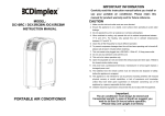
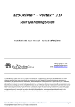
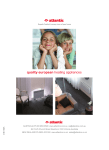
Infrared Panel Heater with Wireless Thermostat
“Frame WIST” Series W 30/60/90/120/150
INSTALLATION AND OPERATION
MANUAL-2011-WIST-v3-eng
1
CONTENTS
1.
PRODUCT SPECIFICATIONS.................................................................................................................................. 3
2.
PACKAGE CONTENTS............................................................................................................................................ 3
2.2.
ASSEMBLED HEATING PANEL ............................................................................................................................... 3
2.3.
THERMOSTAT ...................................................................................................................................................... 4
3.
INSTALLATION ........................................................................................................................................................ 4
3.1.
FIRST-TIME SETUP .............................................................................................................................................. 4
3.2.
SETTING THE TIME AND DATE ............................................................................................................................... 4
4.
FUNCTIONALITY SETS ........................................................................................................................................... 5
5.
SERVICE MENU (PR1 – PR15)................................................................................................................................ 5
Pr 1 LCD Backlight .............................................................................................................................................. 5
Pr 2 Switch between 7+0 and 5+2 programs ....................................................................................................... 5
Pr 3 Optimal start................................................................................................................................................. 5
Pr 4 Regulation type ............................................................................................................................................ 5
Pr 5 ON-OFF regulation hysteresis parameter .................................................................................................... 6
Pr 6 P constant of PI regulator............................................................................................................................. 6
Pr 7 I constant of PI regulator .............................................................................................................................. 6
Pr 8 Product firmware version ............................................................................................................................. 6
Pr 9 Reset to factory defaults .............................................................................................................................. 6
Pr 10 Pairing and unpairing panel(s) to a thermostat ............................................................................................ 6
Pr 11 Display temperature in Celsius or Fahrenheit scale ..................................................................................... 7
Pr 12 Frost guard................................................................................................................................................... 7
Pr 13 Frost guard threshold ................................................................................................................................... 7
Pr 14 Temperature sensor calibration .................................................................................................................... 8
Pr 15 Thermostat functionality set ......................................................................................................................... 8
6.
LED INDICATOR (PANEL STATUS) ........................................................................................................................ 8
7.
RAPID HEATING & ECO MODE .............................................................................................................................. 8
8.
KEYPAD LOCK ........................................................................................................................................................ 8
9.
THERMOSTAT BATTERY ........................................................................................................................................ 8
10.
THERMOSTAT MODES ....................................................................................................................................... 8
10.1. MANUAL MODE ................................................................................................................................................... 8
10.2. AUTO MODE ....................................................................................................................................................... 9
10.3. AUTO + MANUAL MODE ....................................................................................................................................... 9
10.4. HOME MODE ...................................................................................................................................................... 9
10.5. HOME + MANUAL MODE ...................................................................................................................................... 9
10.6. HOLIDAY (AWAY) MODE ....................................................................................................................................... 9
11.
SCHEDULED HEATING PROGRAMS................................................................................................................. 9
11.1. AUTO MODE (
) - WEEKLY PROGRAMMING .................................................................................................. 9
11.2. HOME MODE (
) - DAILY PROGRAMMING ..................................................................................................... 10
12.
CHANGING THE TIME AND DATE ................................................................................................................... 10
13.
TURNING OFF THE PANEL & THERMOSTAT ................................................................................................. 10
14.
SAFETY NOTES ................................................................................................................................................ 11
MANUAL-2011-WIST-v3-eng
2
1. PRODUCT SPECIFICATIONS:
Model Number
W30
596mm x 296mm x
58mm
W60
596mm x 596mm x
58mm
W90
596mm x 896mm x
58mm
W120
596mm x 1196mm x
58mm
W150
596mm x 1496mm x
58mm
Max. Wattage
500W
500W
800W
1000W
1300W
Panel Weight
4.5 kg
7.2 kg
10.2 kg
13.2kg
16.2 kg
4.4A
5.7A
Dimensions*
Input Power
230V~ 50-60Hz
Current
1A
2.2A
Power Cable
3.5A
Length 2m with Earthed connection plug
Glass
Tempered glass or tempered mirror - Max. surface temperature 125°C
Frame
Aluminum profile
Effective Area
6m2
10m2
15m2
20m2
25m2
* Assembled dimensions, with mounting hardware for wall/ceiling
2. PACKAGE CONTENTS:
Wireless Thermostat
Heating Panel
Screws/ plugs for wall (x4)
Power Cable (2m)
Washers
(x4)
Mounting
bracket
screws (x4)
Screws/ plugs for
thermostat (x2)
Mounting Brackets (x4)
Thermostat
back cover
(x1)
Installation Template
10mm wrench (x1)
2.2. Assembled Heating Panel
Back view. The front heating surface is tempered safety glass surrounded by aluminum framing
LED Indicator
On / Off Switch
Panel
Identification Number
Electronics / Antenna
Housing
Mounting Brackets
Power Cable
Power Cable Socket
MANUAL-2011-WIST-v3-eng
3
2.3. Thermostat
3. INSTALLATION:
The heater should not be obstructed by or placed behind furniture or other objects (see also safety notes). Because of its IP rating
(IP50), when installing in bathrooms or kitchens, the panel must be placed at a position where it will not come into contact with
water (see Safety notes, page #10). The heater should be installed at a position where occupants would normally be at the same
distance from it.
Once the most favorable installation position has been identified, please follow these steps:
Step 1: Place the installation template on the wall using tape, ensure that it is level, and mark the 4 locations of the holes for the
wall plugs and mounting screws. Verify that there are NO electrical cables in the wall where you will be drilling. It is also advised to
choose a location for the panel where there is no metal content or electrical cabling 10cm or less from the plastic housing of the
electronic components (this contains the antenna).
Step 2: Use a drill bit suitable for the wall material type. For concrete/ brick walls, use a drill with a diameter of 8mm.
Step 3: Put the wall plugs in the holes and fix the screws until the head of each remains about 1 cm from the wall. Plugs for solid
(concrete, brick) walls are provided. In case of doubt, please ask for assistance from a professional.
Step 4: Hang the panel using its mounting brackets on the screws, and then close the 2 security tabs for added safety. Be sure
that the power cable does not cross over the rear component box. This may in some cases cause a lower reach in distance of
signals between the thermostat and heating panel.
Step 5: Remove the back cover from the thermostat and then remove the paper which separates the battery from its (+) contact
terminal. Replace the cover and secure it with the smallest screw provided in the bag of mounting screws. Plug the power cord of
the panel into a standard electrical wall outlet.
3.1. First-time Setup:
The heating panel and thermostat supplied in each box are paired (pre-assigned) to function together at manufacture. Follow the
pairing / unpairing procedure under Pr 10 in the Service Menu (page #6) only if necessary – for example when pairing 2 or more
panels to one thermostat.
3.2. Setting the Time and Date:
When the battery is inserted back into the thermostat, all elements on the LCD will display briefly. “Time” will then appear and the
flashing elements for HOUR, MINUTE, DAY, MONTH and YEAR can be increased or decreased with the
or
keys, then
confirmed with the
key as illustrated in the sequence below (see also section 12, page #10):
Afterward, the default mode is
(manual), the default set temperature is 20°C and thermostat
functionality is in “SIMPLE” functionality (example at right). Rapid heating is also enabled by default –
indicated by the
symbol. To the right, 23.4°C is displayed on the LCD, but this is only an example
of real room temperature, not the set temperature. The desired room temperature can be viewed or
changed by pressing the
or
keys.
MANUAL-2011-WIST-v3-eng
4
4. FUNCTIONALITY SETS:
After initial start-up, SIMPLE functionality is enabled by default. There are two types of functionality sets:
SIMPLE functionality set - without the option to schedule ENHANCED functionality set means that all functions
heating programs. The thermostat has limited functions on the described in this manual are enabled and may be modified.
main screen. The user sets the temperature with
or
in
/
/
.
(manual) mode. This is similar to using a normal type AUTO, HOME, AWAY, All 15 parameters in the Service Menu may be edited (Pr1thermostat with a control dial.
Pr15).
(MAX mode) is also active by default and uses the
maximum power capacity of the heating panel until the desired ECO Mode – energy saving mode, uses 50% power (see
section 7, page #8)
temperature is reached (see section 7, page #8).
Other functions in SIMPLE functionality are:
• energy saving mode with possibility of time&date adjustment (section 12)
• service menu with access to most of its sub-functions (see sections 5)
*** To switch between the 2 functionality sets, use parameter 15 (see Pr 15, page #7) ***
5. SERVICE MENU (Pr1 – Pr15):
The purpose of this menu is the full configuration of the thermostat parameters.
(Note: The parameters are pre-configured for optimal usage, with the exception of pairing and un-pairing - Pr10.)
The service menu is activated by holding down
for 5 seconds. To save the changes to any setting and exit, use
the same combination
(hold for 5 seconds), or press the
button to save the setting change and then move
on to the next menu item. If no button is pressed, the menu automatically turns off after 1 minute and the new setting will be saved.
5 seconds
Pr 1
LCD Backlight
[0]=OFF, [1]=ON / default: [0]
With this option turned on, the LCD background will light up for 5 seconds
after any keypress. Activation of backlighting reduces battery life.
*ACCESSIBLE ONLY IN ENHANCED FUNCTIONALITY*
Pr 2
Switch between 7+0 and 5+2 programs
5 seconds,
x1
5 seconds,
x2
5 seconds,
x3
[0]=7+0 and [1]=5+2 programs / default: [1]:
7+0 is to set different temperature schedules for every day of the week.
5+2 is to set temperature schedules for weekdays, and another for weekends
(default).
***SEE PAGE #9 CHAPTER 11 FOR INSTRUCTIONS***
*ACCESSIBLE ONLY IN ENHANCED FUNCTIONALITY*
Pr 3
Optimal start
[0]=OFF, [1]=ON / default: [0]
“Optimal start” - when set to [1] = ON, the system can start heating in
advance to reach the desired temperature on time. For instance, if the user
has 22°C set for 7 am, normally the thermostat will send signals to the panel
to start heating at 7 am. When “Optimal start” is on, heating will begin in
advance to reach the desired temperature on time; 22°C at 7 am in this case.
The thermostat has a built-in algorithm to start heating at the optimal time in
advance in order not to overheat the room.
Pr 4
Regulation type
[0]=ON/OFF and [1]=PI regulation / default: [0]:
If set to [0], classic ON-OFF regulation with set hysteresis (see parameter
Pr5) is used. If set to [1], PI regulation is used (see Pr 6 and 7).
Hysteresis regulation at times exceeds and falls below the desired
temperature in a gradually narrowing cycle until the desired temperature is
reached.
PI regulation also ensures an almost constant temperature, but in contrast to
hysteresis regulation, it is reached by gradually increasing the temperature to
its desired level at specified increments.
MANUAL-2011-WIST-v3-eng
5
Pr 5
ON-OFF regulation hysteresis parameter
defaults: [0.2°C / 0.4°F]
This setting defines temperature increments at which the thermostat controls
the heating panel and monitors room temperature. It may be set from 0.1°C to
10°C at an accuracy of 0.1°C. If the Fahrenheit scale is used, the value may
be changed from 0.2°F to 18°F at an accuracy of 0.2°F. The default settings
are optimal in most cases and should not be modified without
professional consultation.
5 seconds,
x4
Pr 6
5 seconds,
x5
5 seconds,
x6
5 seconds,
x7
5 seconds,
x8
P constant of PI regulator
defaults: [30 - Celsius / 54 - Fahrenheit]:
May be set from 0.0 to 55.0 when using the Celsius scale, or from 1.8 to 99.0
when using the Fahrenheit scale. Temperature scales are modified under
parameter 11. The default settings are optimal in most cases and should
not be modified without professional consultation.
Pr 7
I constant of PI regulator
defaults: [1 - Celsius / 1.8 - Fahrenheit]:
May be set from 0.0 to 55.0 when using the Celsius scale, or from 1.8 to 99.0
when using the Fahrenheit scale. Temperature scales are modified under
parameter 11.
The default settings are optimal in most cases and should not be
modified without professional consultation.
Pr 8
Product firmware version
The thermostat firmware version will display when the user reaches
parameter 8. To leave the menu press
.
Pr 9
Reset to factory defaults
After setting this parameter to [1], all values that have been modified by the
user and stored in the thermostat's memory will be cleared, including control
of any previously paired panels. The thermostat will operate as new, set back
to its factory default parameters.
Pr 10
Pairing and unpairing panel(s) to a thermostat
The thermostat and panel which are supplied together in the box have already been paired at manufacture. Follow the instructions here when
pairing an additional panel to a thermostat. One thermostat may control up to 10 heating panels. Each panel has a unique 8-digit label (panel ID number)
which is located on the plastic cover of the control unit on the panel rear (eg: 00-00-20-C3). The pairing process is only possible if both the thermostat and
panel are turned on. First, the thermostat will search (scan) for active heating panels. The found panel can then be paired with a thermostat. If a panel was
paired to the thermostat previously, its 8-digit ID number will scroll on the display.
Pairing positions may be either:
a) empty, displayed in text as "NONE" on the LCD or
b) occupied (already controlling a panel) and the panel ID number scrolls on the display
PAIRING TO ONE PANEL:
1. Activate the service menu on the thermostat and locate “Pr10” (this is the
scanning / pairing parameter).
2. “Pr 10” and the letters “PE” will flash on the LCD.
3. Press
4. The LCD will scroll the phrase “TO START SCANNING PRESS PLUS – TO
START PAIRING PRESS SET”
5. Pressing
on the thermostat will begin a search for any available panels.
This takes approximately 40 seconds.
6. The LCD will display the number of available panels. In the event that the
thermostat will not find a panel, "NO INFRAPANEL FOUND – RESTART
SCANNING AND PAIRING?” will scroll across the display. To continue
scanning, press
7. Whether the display panel found the number, press the
button or
wait 40 seconds.
MANUAL-2011-WIST-v3-eng
6
5 seconds,
x9
8. The LCD displays the message “AN INFRAPANEL FOUND” and the
message that it is not yet saved “NONE”
9. Press the
and
buttons to select the position where the panel will be
saved.
10. Press
and then
11. Next, the LCD displays the ID number of the panel and the position
number will flash.
12. Press
13. The display shows “DONE” and “SAVE”
14. The panel is paired and saved to the first position. To exit the menu, press
the
button 3x.
and
PAIRING A SECOND PANEL TO THE SAME THERMOSTAT:
1. The same procedure is followed to add a second panel to the thermostat.
2. In the above example, a panel was assigned to position 1. Now we will add
a panel at position 2.
3. Repeat steps 1-8 from the previous section.
4. Use
or
to select the position at which the panel will be assigned (in
this case at position 2).
5. Press
and then
6. Next, the LCD displays the ID number of the panel and the position number
will flash.
7. Press
8. The display shows “DONE” and “SAVE”
9. The panel is paired and saved at the second position. To exit the menu,
press the
button 3x.
and
UNPAIRING PANELS:
1. Standard working screen.
2. Press
and
for 5 seconds to enter the service menu.
3. Press
9 times to select parameter 10 (Pr 10).
4. Enter the scanning / pairing menu by pressing
5. Press again.
6. Select the panel you would like to remove at its position using
and
7. Press
to confirm.
8. Press
to unpair (remove) the panel from the thermostat's control.
9. The panel has been unpaired and screen will display “DONE”.
Pr 11
5 seconds,
x10
5 seconds,
x11
5 seconds,
x12
Display temperature in Celsius or Fahrenheit scale
[0]=Celsius, [1]=Fahrenheit / default: Celsius:
Choose between using the Celsius or Fahrenheit scale.
Pr 12
Frost guard
[0]=OFF [1]=ON / default [0]=FF:
This enables the feature to prevent the panel electronics from falling below
freezing temperatures while plugged in. Only necessary for extreme cases/
environments.
Pr 13
Frost guard threshold
default [5]=5°C:
If the frost guard is enabled, temperatures between 5°C-10°C / 40°F-50°F
may be selected. If the panel structure falls below this temperature, the frost
guard will activate.
MANUAL-2011-WIST-v3-eng
7
Pr 14
Temperature sensor calibration
5 seconds,
x13
5 seconds,
x14
default [0]=0°C/°F:
May be set from -2.5°C to +2.5°C at increments of 0.1°C, or from -4.5°F to
4.5°F at increments of 0.1°F.
Pr 15
Thermostat functionality set
default [0]=SIMPLE:
[0] SIMPLE functionality. Temperature is controlled (up/down) with no
additional programming.
[1] ENHANCED functionality. Enables the option to program scheduled
heating by day of the week, time, etc. in the AUTO, HOME, and AWAY
settings /
/
6. LED INDICATOR (PANEL STATUS):
Located on the component housing at the rear of the heating panel.
Responds
Responds to
to scanning/
un-pairing
pairing
Panel
State
LED
Status
Description
Heating
Activity
Pairing
Status
1
Red, flashing
Default state
Not heating
Un-paired
Yes
No
2
Green,
continual
Normal, working
Heating according to
program
Paired
No
Yes
3
Green, flashes
for 3 minutes
until it receives
signal
Temporary state,
after state #2, if
previously paired
panel is restarted
Not heating until signal
is received from
thermostat
Paired
No
Yes
4
Red, continual.
If thermostat does Not heating until signal
not respond for 5
is received from
minutes or more
thermostat
Paired
Yes
Yes
LED
7. RAPID HEATING & ECO MODE:
Rapid Heating (
) is enabled by default and uses the maximum power capacity of the heating panel until the desired
temperature is reached. To disable it and use 50% power - Eco Mode - (in ENHANCED functionality only), press the
and
buttons simultaneously for a period of 5 seconds, then the
symbol will disappear. Re-enable it with the same key sequence.
Eco mode may also be used in SIMPLE functionality by switching back to SIMPLE (Pr 15) when the
symbol is not visible on
the LCD. To reactivate
in SIMPLE functionality, it must first be enabled while in ENHANCED functionality (Pr 15).
8. KEYPAD LOCK:
ENHANCED functionality only.
Accidental changes to thermostat settings by children or other persons can be prevented by locking the keypad. This is done by
holding down the
and
keys simultaneously for 3 seconds, display shows
. Repeat the procedure to unlock.
9. THERMOSTAT BATTERY:
One battery powers the thermostat and it should last for 2 - 3 years. When low battery voltage is detected, an “empty battery” sign (
) will appear at the middle left part of the display. When replacing the battery, use only 3.6 volt, AA-size Lithium Thionyl
Chloride type - (Li-SOCl2) type ER 14505(M). Note: Inserting the battery at reversed polarity may damage the unit.
10. THERMOSTAT MODES:
Thermostat control is very straightforward. It works in the following modes (heating programs):
10.1. Manual Mode
(Accessible in SIMPLE or ENHANCED functionality)
This is the simplest mode, and the default. When the thermostat starts up for the first time, this mode is active with a default set temperature of 20°C. To
enable
from another mode (heating program), click the
button until the
symbol appears at the bottom of the display.
To set desired temperature, press the
or
buttons. When the desired temperature is set, it will flash for 3 seconds and then will be saved to the
memory. If either of the two buttons is held down longer, the set temperature on the LCD will advance faster. The set temperature range is from 5°C to 35°C at
steps 0.5°C, or 41°F to 95°F at steps of 0.5°F.
MANUAL-2011-WIST-v3-eng
8
10.2. Auto Mode
-
(Accessible in ENHANCED functionality)
To enter this mode from another mode (heating program), click the
button until the
symbol appears at the bottom of the display. The preprogrammed weekly program then becomes active – see section 11.1 below for programming instructions.
10.3. Auto + Manual Mode -
(Accessible in ENHANCED functionality)
This mode is activated in
mode. When
is activated, press
or
buttons. Its purpose is to temporarily change the set temperature in
mode (the weekly program) to a different value. This may come into account when the user is not satisfied with the current, pre-programmed setting.
This mode is equivalent to
mode, the only difference being its duration.
mode is permanent,
+
mode expires:
• with the next time-temperature change in the daily program and then
mode is active again,
• If the
button is pressed by the user, the thermostat will go back to its previously set mode.
10.4. Home Mode -
(Accessible in ENHANCED functionality)
HOME
mode is nothing else but a daily program. When this mode is active, all 7 days of week will use the same heating program. The purpose of this
mode is in case that the user doesn't want to program an entire
mode, but quickly schedule a heating program that heats during the day and saves
energy at night.
To enter this mode from another mode (heating program), click the
button until the
symbol appears at the bottom of the display. The preprogrammed daily program then becomes active – see section 11.2 below for programming instructions.
10.5. Home + Manual Mode This mode is activated from Home
Home
(Accessible in ENHANCED functionality)
mode. When
is activated, press
buttons. Its purpose is to temporarily change the set temperature in
mode to a different value. This may come into account when the user is not satisfied with the current pre-programmed setting. This mode is
equivalent to
mode, the only difference being its duration.
• with the next time-temperature change in the daily program and then
• If the
or
mode is permanent,
+
mode is active again,
mode expires:
button is pressed by the user, the thermostat will go back to its previously set mode.
10.6. Holiday (Away) Mode
-
(Accessible in ENHANCED functionality)
The purpose of this mode is to set one temperature level for a selected period of time (for instance during a vacation or business trip), without the need to reprogram the weekly program settings in
mode. To invoke this mode, hold
for 3 seconds. Then, with
or
set the period for how long the
new temperature should be maintained. First, hours are shown and then, if more than 24 hours is required, the increments change to days. The maximum
interval is 99 days. When the interval is defined, the user is prompted to set the required temperature (again with
must be made with the
button and Holiday Mode becomes active immediately – the suitcase (
mode can end in the following two ways:
• When the set period is over, the thermostat will go back to its previously set mode.
• If the
or
) for this period. Confirmation
) symbol will display at the bottom of the LCD. This
button is pressed by the user, the thermostat will go back to its previously set mode.
11. SCHEDULED HEATING PROGRAMS (Available in ENHANCED Functionality)
11.1. AUTO mode (
)-
Weekly Programming:
Thermostat allows for two different types of weekly programming schedules; To modify 5+2 mode:
“5+2” and “7+0”. To choose between them, go to Service menu, Pr 2.
1. Press the
button for 3 seconds.
2. The numbers “1 2 3 4 5” will blink on the LCD (weekdays).
5+2 is factory-set as the default [1]. See page 5 (Pr2) to switch to 7+0 [0].
3. Press
to begin setting the time for T1 (weekdays).
In 5+2 mode, one temperature schedule is set for weekdays (1 2 3 4 5 = Mon 4. Choose the hour for T1 with
and
.
– Fri), and another for weekends (6 7 = Sat, Sun).
5. Press
to confirm the hour.
6. Choose the minute for T1 with
The pre-set times and temperatures for 5+2 weekdays are:
7. Press
T1
T2
T3
T4
T5
T6
06:00
08:00
14:00
20:00
22:00
23:55
and
.
to confirm the minute.
8. The desired temperature will flash. Use
or
to select.
9. Press
to confirm the temperature for T1 and repeat the same steps
as
above
for
times
T2 to T6.
22°C
20°C
22°C
22°C
20°C
20°C
10. After setting all of the schedule parameters, the message “SAVE” will will
appear on the LCD. The heating program is now assigned for weekdays.
The above table illustrates that the panel will begin to heat the area to 11. The numbers “6 7” will blink on the LCD (wekends).
22°C from 06:00 to 08:00 in the morning. After 08:00 the temperature is set at
to begin setting the time for T1 (weekends).
20°C until 14:00 in the afternoon. Beginning at 14:00, the room temperature is 12. Press
set to 22 ° C until 22:00. Thereafter, heating is set to 20°C until 06:00 the next 13. Choose the hour for T1 with
and
.
morning. This heating schedule is repeated five days a week (from Monday to
MANUAL-2011-WIST-v3-eng
9
Friday).
The pre-set times and temperatures for 5+2 weekends are:
14. Press
to confirm the hour.
15. Choose the minute for T1 with
and
T1
T2
T3
T4
T5
T6
16. Press
07:00
08:00
14:00
20:00
23:00
23:55
17. The desired temperature will flash. Use
.
to confirm the minute.
or
to select.
18. Press
to confirm the temperature for T1 and repeat the same steps
as above for times T2 to T6.
19. After setting all of the schedule parameters, the message “SAVE” will will
The above example shows that the panel will hold the room temperature at appear on the LCD. The heating program is now assigned for weekends.
22°C from 07:00 until 23:00. Beginning at 23:00, the temperature is set to
20°C until 07:00. This cycle will repeat the next weekend day.
7+0 mode allows you to set different times and temperatures for each
day of the week. Its programming procedure follows the same steps as
In 7+0 mode, different temperature schedules may be set for each day of above.
the week.
22°C
22°C
22°C
11.2. HOME mode (
22°C
20°C
20°C
) - Daily Programming:
HOME
mode is nothing else but a daily program. It also has 6 events
(for time/temperature), like
mode. The only difference is that when
this mode is active, all 7 days of week will use the same heating program. The
purpose of this mode is in case that the user doesn't want to program an
entire
mode, but quickly schedule a heating program that heats
during the day and saves energy at night.
T2
T3
T4
T5
2. Press
3. Press
button for 3 seconds.
until the HOME (
to begin programming the time T1.
4. Choose the hour for T1 with
5. Press
) symbol appears on the LCD.
and
7. Press
and
.
to confirm the minute.
8. The desired temperature will flash. Use
T6
.
to confirm the hour.
6. Choose the minute for T1 with
The pre-set times and temperatures for HOME mode are:
T1
1. Press the
or
to select.
9. Press
to confirm the temperature for T1 and repeat the same steps
as above for times T2 to T6.
22°C
22°C
22°C
22°C
20°C
20°C
10. After setting all of the schedule parameters, the message “SAVE” will will
appear on the LCD. The heating program is now assigned for every day of the
The above example shows that the panel will hold the room temperature at week.
22°C from 07:00 until 23:00. Beginning at 23:00, the temperature is set to
20°C until 07:00. This cycle repeats every day of the week.
07:00
08:00
14:00
20:00
23:00
23:55
12. CHANGING THE TIME AND DATE
The time and date may be set either during initial start-up (when the battery is inserted) – (see section 3.2) or through the
programming menu (accessible in ENHANCED functionality only). To change the time/date, hold the
button down for 3
seconds from the main screen to enter the programming menu, and then press
until the time is displayed. Press
again,
and the time, day of week, month and year may now be modified by using the same process described in section 3.2.
13. TURNING OFF THE PANEL & THERMOSTAT
(Accessible in SIMPLE or ENHANCED functionality)
The panel can be switched off by simply using the On/Off switch at the back of the panel.
Pairing information will be retained by the thermostat and the panel will continue its previous
heating program/setting when switched back on.
“Standby Mode” (OFF) is entered by pressing and holding down the
and
buttons
simultaneously for a period of 5 seconds. Afterward, all of the display segments turn off and
the thermostat is in “Standby Mode”. In this state, the thermostat uses a minimum of battery
power and stops all communication with its paired heating panels. The paired heating
panels will enter state #4 (continual, red LED) after 5 minutes and stop heating. This
function may be used at the end of the heating season to ensure maximum battery life and
deactivate the heating system. If any key is pressed on the thermostat afterward, it will
restart and the user will be prompted to re-enter the time and date. This function may also
On/Off switch
be used in SIMPLE mode to set the time and date without replacing battery.
MANUAL-2011-WIST-v3-eng
10
14. SAFETY NOTES:
•
•
•
•
•
•
•
•
•
•
•
•
•
•
•
•
•
Heating panel models W30, W60, W90, W120, and W150 are suitable for wall or ceiling installation and are equipped with
mounting brackets to provide support. Please read the installation guidelines before installing the panel.
The appliance is safe to touch; however, prolonged contact with the panel while it is in operation may cause injury.
Small children should not be left unattended near the heating panel as prolonged contact with the panel may cause injury.
If any fluids or foreign object may become lodged within the panel, disconnect it from power and have it checked by a
service technician.
The appliance has an earthed power cord which is to be used with 220V power outlets. In case the power cord or the
appliance itself becomes damaged, it should be repaired by a professional.
Do not attempt to disassemble the appliance. It contains many parts and the warranty will become void. Dis-assembly and/
or reassembly should not be done outside the factory or a specialized service center.
To avoid electrocution, remove the power cord if a defect has been identified, or if the panel is to be moved.
Protection against overheating and fire hazard: The panel can at instances reach a surface temperature of 125°C. DO NOT
cover the panel at any time nor put easily flammable fabrics or other objects directly in front of the panel.
Before drilling into the wall for installation, first check that the area is free of electrical wires, gas or water pipes or any other
obstacles that could be damaged.
First time use: verify that all of the packaging materials have been removed. In case you notice an odor due to panel
operation, switch it off immediately, then identify and remove the source. In case the smell persists, contact your point of sale.
Do not install the heating panel directly over (covering) its electrical socket.
Install the panel where its plug will be easily accessible.
Do not in any case use the heating panel if its glass surface is cracked or otherwise damaged.
FIRST panels are designed to withstand moderate power drops/surges at voltages between 220V and 250V. Verify before
use that the panel you are installing is suited for your regional supply voltage. When this would not be the case, do not plug
in the appliance and contact your supplier. In case the panel is plugged into an outlet with the wrong voltage, or when power
surges are out of the range as described before, the warranty will NOT cover these damages.
Do not attempt to clean the heating panel while it is connected to the electrical power supply. First unplug the power cord,
and then the appliance may be cleaned with a soft, dry cloth.
Battery Disposal: Thermostat batteries intended for disposal are considered hazardous waste and may not be included with
municipal waste. Please follow your local laws and procedures for proper disposal of these materials.
The appliance is suitable for use in bathrooms at ZONE 3 or further from water sources. The illustration on the following page is
for reference. In all cases, be sure that the power outlets in your bathroom are equipped with an RCD (Residual Current
Device) to protect the electrical circuit.
MANUAL-2011-WIST-v3-eng
11
FIRST Heating s.r.o.
Revoluční 3
110 00 Praha 1
Czech Republic
©2011 FIRST Heating s.r.o.
MANUAL-2011-WIST-v3-eng
12
Tel: (+420) 227 629 790 / 791
[email protected]
www.firstheating.com