1
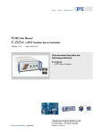
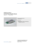
PZ 45E User Manual E-660 Release: 2.2.3 Single-Channel LVPZT Amplifier Date: 2005-01-31 This document describes the following product(s): E-660.00 Single-Channel Amplifier for LVPZTs, desktop version E-660.OE Single-Channel Amplifier for LVPZTs, OEM version © Physik Instrumente (PI) GmbH & Co. KG Auf der Römerstr. 1 ⋅ 76228 Karlsruhe, Germany Tel. +49 721 4846-0 ⋅ Fax: +49 721 4846-299 [email protected] ⋅ www.pi.ws Declaration of Conformity according to ISO / IEC Guide 22 and EN 45014 Manufacturer: Manufacturer´s Address: Physik Instrumente (PI) GmbH & Co. KG Auf der Römerstrasse 1 D-76228 Karlsruhe, Germany The manufacturer hereby declares that the product Product Name: Model Numbers: Product Options: High-Voltage Amplifier E-660.00 none conforms to the following EMC Standards and normative documents: Electromagnetic Emission: EN 61000-6-3, EN 55011 Electromagnetic Immunity: EN 61000-6-1 Safety (Low Voltage Directive) : EN 61010-1 August 24, 2004 Karlsruhe, Germany Dr. Karl Spanner President Copyright 1999–2005 by Physik Instrumente (PI) GmbH & Co. KG, Karlsruhe, Germany. The text, photographs and drawings in this manual enjoy copyright protection. With regard thereto, Physik Instrumente (PI) GmbH & Co. KG reserves all rights. Use of said text, photographs and drawings is permitted only in part and only upon citation of the source First printing 2005-01-31 Document Number PZ 45E, Release 2.2.3 E-660_UserPZ45E223.doc This manual has been provided for information only and product specifications are subject to change without notice. About this Document Users of this Manual This manual is designed to help the reader to install and operate the E-660 Single-Channel LVPZT Amplifier. It assumes that the reader has a fundamental understanding of basic electronics and applicable safety procedures. Updated releases are available via FTP or email: contact your Physik Instrumente sales engineer or write [email protected]. Conventions The notes and symbols used in this manual have the following meanings: DANGER Indicates the presence of high voltage (> 50 V). Calls attention to a procedure, practice or condition which, if not correctly performed or adhered to, could result in injury or death. Contents 1 Introduction 1.1 1.2 2 3 6 Operating Modes........................................................................6 E-660.OE Application Examples ................................................6 Technical Data 4.1 4.2 4.3 4.4 4 Modes of Operation....................................................................4 Quick Start .................................................................................4 Front and Rear Panel Elements .................................................5 E-660.OE 3.1 3.2 4 Models:.......................................................................................2 Safety Precautions .....................................................................2 E-660.00 Desktop Unit 2.1 2.2 2.3 2 8 Specifications .............................................................................8 Wall-Plug Power Supply.............................................................9 E-660.OE Dimensions..............................................................10 E-660.OE Pin Locations and Assignments ..............................11 Introduction 1 Introduction The E-660 LVPZT amplifier is a single-channel low-power voltage source and amplifier for driving Low-Voltage Piezoelectric Translators (LVPZTs). Many applications of LVPZTs require only low-power amplifiers. Because the power consumption of a piezoelectric translator depends on the operating frequency and the expansion amplitude, static or slow-motion movements can be accomplished by low-cost low-power amplifiers. Both E-660.00 and E-660.OE amplifiers are inexpensive drivers for LVPZTs having an average output power of about 2 W. The E-660.OE is an OEM module for PCB mounting. The hermetically sealed metal casing has solderable pins and can be used as a single-component amplifier for LVPZTs. The E-660 is a desktop device having some operating elements (on the front panel) and cable connectors for analog signal input and PZT output. Operating voltage is +12 V supplied by a wallplug power supply. 1.1 Models: E-660.OE E-660.00 1.2 Single-channel LVPZT Amplifier module for OEM Applications Single-channel LVPZT Amplifier as desktop device Safety Precautions DANGER Be aware that both E-660 models are Voltage Amplifiers capable of outputting voltages up to 100 volts. This voltage may cause electric shock if the device is handled improperly. To avoid danger, follow the instructions below: www.pi.ws E-660 PZ 45E Release 2.2.3 Page 2 Introduction Do not open the chassis while the line power cord is connected! Do not touch any part that may be connected to the voltage output! Make sure that the metal casings of all PZT elements connected to the voltage output are properly grounded. www.pi.ws E-660 PZ 45E Release 2.2.3 Page 3 E-660.00 Desktop Unit 2 E-660.00 Desktop Unit 2.1 Modes of Operation Manual operation Output voltage can be set by a 1-turn DC-offset potentiometer in the range of 5 to 100 V. External operation Output voltage is controlled by an analog signal varying in an 11-volt range applied to the BNC input. The DC-offset potentiometer can effectively add a positive DC bias (offset) of 0 to 10 V to this input, allowing shifting of the input range. Input plus bias must be between 0 and +11 V, which, multiplied by the gain factor of 10, gives an output voltage range of +5 to +110 V (outputs under +5 V are not useable). 2.2 Quick Start www.pi.ws 1 The E-660 Amplifier is a desktop device with a stabilized external wall-plug AC-line power supply. Make sure the supply is compatible with the local AC line voltage and is set to output 12 V with the plug tip positive (see p. 9). 2 Connect the external power supply to the +12 V supply socket on the rear panel and plug it into the local line power. 3 Turn the DC Level potentiometer full counterclockwise (CCW) to set the output to zero. 4 Connect the Low-Voltage Piezoelectric Translator to the LVPZT-OUT socket at the front panel. 5 For manual operation, turn the DC Level potentiometer clockwise (CW) to increase the output voltage and to expand the LVPZT. 6 For external operation, apply an analog voltage to the INPUT socket. The input voltage can be biased (offset) E-660 PZ 45E Release 2.2.3 Page 4 E-660.00 Desktop Unit by up to 10 V by the DC LEVEL potentiometer. The result, bias plus Input must be in the 0 to 11 V range. The LVPZT output varies within the +5 to +110 V range. Outputs below 5 V are not useable. 2.3 Front and Rear Panel Elements OUT IN DC OFFSET LEMO Socket to connect one low-voltage PZT Translator (LVPZT). BNC socket for control Input signal Potentiometer for manual setting of the input voltage offset. Can be used in conjunction with a control signal applied at the IN connector. Fig. 1: E-660.00 Front and Rear Panels www.pi.ws E-660 PZ 45E Release 2.2.3 Page 5 E-660.OE 3 E-660.OE The E-660.OE Amplifier OEM module is packaged in a metal case with solder pins for PCB mounting. The module requires single +12 to +15 VDC supply for operation. 3.1 Operating Modes The E-660.OE amplifier module can be used for applications requiring potentiometer-, amplifier-, or combined-mode operation: 3.2 1 Manual operation via potentiometer. The necessary reference voltage is provided by the module. For sample application circuitry, see Fig. 2. The offset input is effectively doubled before being used to bias the control input. 2 Amplifier operation, using external control signal. See Fig. 3. 3 Combined-mode: amplifier operation with additional manual offset adjustment. An external potentiometer can be used to offset the output. See Fig. 4. The offset input is effectively doubled before being used to bias the control input. E-660.OE Application Examples Fig. 2: E-660.OE Operation using external potentiometer www.pi.ws E-660 PZ 45E Release 2.2.3 Page 6 E-660.OE Fig. 3: E-660.OE : Amplifier mode Fig. 4: E-660.OE: Amplifier mode with offset adjustment www.pi.ws E-660 PZ 45E Release 2.2.3 Page 7 Technical Data 4 Technical Data 4.1 Specifications Models E-660.00 E-660.OE Channels 1 1 Output voltage range:* +5 V to +110 V +5 V to +110 V Max. output current: 20 mA (sink/source) 20 mA (sink/source) Output protection: short circuit protected short circuit protected Max. output power: 2W 2W DC-offset setting Front panel 1-turn potentiometer adds 0 to +10 V to Control input** Adds double value on pin 5 (0-5 V) to Control In, see p. 7 Fig. 4 *** Control input range + DC offset:** 0 to 11 V 0 to 11 V Input impedance: 100 k-ohm 10 k-ohm Gain: 10 10 Reference output, see p. 6: - +5 V Power supply Wall-plug type w 3.5 mm jack not included Operating voltage: +12 V to +15 V, stabilized +12 V to +15 V, stabilized Current requirements: 50 mA (idle), 150 mA max. 50 mA (idle), 150 mA max. Cut-off frequency: 500 Hz, small signals 500 Hz, small signals Ripple output: <20mVpp (with 1 µF load at the output) <20mVpp (with 1 µF load at the output) Operating temperature range: 5° to +50° C (over 40°C, max. av. power derated 10%) 5° to +50° C (over 40°C, max. av. power derated 10%) Case for: Plastic box with aluminum Metal shielded casing, front panel, size: size: 93 x 45 x 28 mm 150 x 195 x 75 mm Weight 0.5 kg 0.25 kg Control input socket: BNC Solder pins**** PZT voltage output socket LEMO ERA.00.250.CTL Solder pins**** *Because outputs below 5 V cannot be reliably generated, corresponding control levels should not be used. ** If, for example, the DC-offset pot on the E-660.00 is set to 5.5, the voltage on the Control In terminal can range from -5.5 to +5.5. ***Note that in the E-660.OE, DC-offset is set by applying a voltage to pin 5. That voltage is effectively doubled before being added to Control In. See p. 6 for wiring examples. ****1 mm diameter, 4 mm length www.pi.ws E-660 PZ 45E Release 2.2.3 Page 8 Technical Data 4.2 Wall-Plug Power Supply The E-660.00 comes with a wall-plug power supply which may have switches for setting the output polarity and (stabilized) voltage. Set the switches on the power supply to the indicated positions: Voltage (Spannung): Polarity (Polaritaet): 12 V tip positive Fig. 5: Set wall-plug power supply to tip positive, 12 V. Switch arrangement and labeling may differ or be absent. www.pi.ws E-660 PZ 45E Release 2.2.3 Page 9 Technical Data 4.3 E-660.OE Dimensions Decimal places separated by commas in drawings Fig. 6: E-660.OE Dimensions www.pi.ws E-660 PZ 45E Release 2.2.3 Page 10 Technical Data 4.4 E-660.OE Pin Locations and Assignments Fig. 7: View from solder side Pin Function 1 2 3 4 5 6 7 8 Operating voltage Input, +12 to +15 VDC Operating voltage GND Reference voltage: +5 V, output GND DC-Offset*, 0-5 V, see p. 6 for wiring examples Control input* LVPZT voltage output, hot side (5 to 110 V) LVPZT voltage output, GND * Control input + 2 x DC-Offset must be in 0 to 11 V range www.pi.ws E-660 PZ 45E Release 2.2.3 Page 11