1
INSTRUTECH CORPORATION
VR-10B USER’S MANUAL
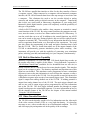
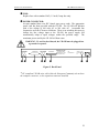
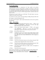
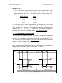
@¢ TRIG 2 OUT:
In playback mode the trigger channel two TTL output plays back the digital
signal recorded on the tape.
If the FR/MEM DISPLAY button is pressed to activate the outputs during
record mode this connector will reflect what is being input to the TRIG 2 IN
connector. When using the VR-10B in the stimulation mode this output
provides user programmable trigger pulses.
7 8
VR-10B DIGITAL DATA RECORDER
FRAME / MEMORY
CRC
POWER
OVERRANGE
CH - 1
9 !º
ERROR
!¶ !• !ª @º
IN
CH - 2
FR/MEM CUE/FR FR
!£ !¢
VOLUME
IN
FRAME
CUE
OUT
OUT
TR-1
INSTRUTECH CORP.
DISPLAY ENTER RESET MODE
2
OUT
CH-2
1 CH 2 CH
ON
1
OUT
CH-1
3 4 5 6
SPKR MIC
IN
TR-2
OUT
IN
OUT
!¡ !™ !∞ !§ @¡ @™ @£ @¢
Figure 4. Front Panel
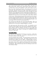
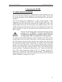
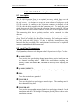
3.2 Rear Panel Controls
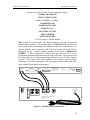
Circled numbers reference to the diagram of the rear panel seen in Figure 5 at the
end of this section.
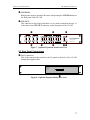
1 VCR VIDEO OUT terminal:
Standard RCA type jack connects to the VIDEO IN of video cassette recorder.
2 VCR VIDEO IN terminal:
Standard RCA type jack connects to VIDEO OUT of the video cassette
recorder.
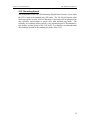
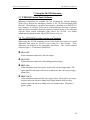
*3 EXPANSION connector:
Provides the auxiliary channel input and output connections. More details on
this connector in the section entitled “Expansion Connector” of the chapter
“Interfacing Connections” and also the chapter entitled “The VR-10B I/O
Panel.”
4 VCR AUDIO IN terminal:
Standard RCA type jack connects to the audio output connector of the video
cassette recorder.
5 VCR AUDIO OUT terminal:
Standard RCA type jack connects to the audio input connector of the video
cassette recorder.
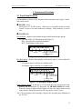
*6 COMPUTER CONNECTOR:
Parallel, serial, and control interface connector. More details on this
connector in the section “Parallel Interface Connector”.
21