1
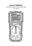
296
Digital Clamp-on
Meter Amp Plus
Instruction Manual
TABLE OF CONTENTS
A. INTRODUCTION
A. INTRODUCTION
1. Congratulations ..........................3
2. Product Description ....................3
3. Declaration of Conformity ..........4
1. Congratulations!!
B. SAFETY CONSIDERATIONS ..............5
C. TECHNICAL DATA
1. Features and Benefits..................7
2. Product Applications ..................8
3. Specifications..............................9
Thank you for purchasing TPI products. The
Amp Plus is easy to use and is built to last.
It is backed by a 3 year limited warranty.
Please remember to complete and return
your product warranty registration card.
2. Product Description
The 296 is a clamp-on plus DMM with True RMS and
Harmonics capabilities. The 296 offers measurements in
all basic electrical functions, plus:
D. MEASUREMENT TECHNIQUES
1. Controls and Functions ............12
2. Step by Step Procedures: ........15
• True RMS
Provides accurate and dependable
readings of non-linear loads.
• HDR Mode
Determines if a signal is clean or
distorted.
E. ACCESSORIES ................................28
• Bar Graph
When measuring frequency, bar
graph indicates current level.
F.
MAINTENANCE ................................29
• TRIM Mode
Smooths out unstable readings.
G. TROUBLE SHOOTING GUIDE ..........30
• Peak Mode
For start-up and inrush currents.
• Sleep Mode
Preserves battery life.
• Data Hold
Holds the reading on the display for
easy viewing.
The 296 comes complete with the following accessories:
Carrying Pouch
Test Lead Set
2
Instruction Manual
Battery
3
3. EC Declaration of Conformity
This is to certify that TPI Model 296 conforms to the
protection requirements of the council directive
89/336/EEC, in the approximation of laws of the member
states relating to Electromagnetic compatibility and
73/23/EEC. The Low Voltage Directive by application of
the following standards:
EN 50081-1
EN 50082-1
EN 61010-1
EN 61010-2-031
EN 61010-2-032
1992 Emissions Standard
1992 Immunity Standard
1993 Safety Standard
1995 Safety Standard
1995 Safety Standard
To ensure conformity with these standard, this instrument must be operated in accordance with the instructions and specifications given in this manual.
B. SAFETY CONSIDERATIONS
! WARNING: Please follow manufacturers test
procedures whenever possible. Do not attempt to
measure unknown voltages or components until a
complete understanding of the circuit is obtained.
GENERAL GUIDELINES
ALWAYS
•
•
•
•
•
CAUTION: Even though this instrument complies with
the immunity standards, it’s accuracy can be affected
by strong radio emissions not covered in the above
standards. Sources such as hand-held radio transceivers, radio and TV transmitters, vehicle radios and
cellular phones generate electromagnetic radiation
that could be induced into the test leads of this instrument. Care should be taken to avoid such situations or
alternatively, check to make sure that the instrument is
not being influence by these emissions.
•
Test the 296 before using it to make sure it is
operating properly.
Inspect the test leads before using to make sure there
are no breaks or shorts.
Double check all connections before testing.
Have someone check on you periodically if
working alone.
Have a complete understanding of the circuit
being measured.
Disconnect power to circuit, then connect test leads to
the 296, then to circuit being measured.
NEVER
•
•
•
•
Attempt to measure unknown high voltages.
Attempt to measure current with the meter in
parallel to the circuit.
Connect the test leads to a live circuit before
setting up the instrument.
Touch any exposed metal part of the test lead assembly.
CAUTION: Please follow manufacturers test procedures whenever possible. Do not attempt to measure
unknown voltages or components until a complete
understanding of the circuit is obtained.
4
5
INTERNATIONAL SYMBOLS
CAUTION: RISK OF ELECTRIC SHOCK
!
C. TECHNICAL DATA
1. Features and Benefits
AC (ALTERNATION CURRENT)
Agency
UL Listed to U.S. and Canadian Safety
Standards. Meets CE and IEC 1010.
DC (DIRECT CURRENT)
True RMS
Needed to accurately measure non-sinusoidal AC voltage and current waveforms
found on many controls and circuits.
HDR Mode
Determines if a signal is clean or distorted.
Displays the harmonic distortion ratio on
ACV and ACA at line voltage and 60 Hz.
4000 Count
Improves the resolution on all functions
and ranges.
Data Hold
Maintains the reading on the display for
hard to reads areas.
Peak Mode
Measure the inrush current of motors,
relays and solenoids.
Trim Mode
Averages the readings for more stable output on LCD.
REFER TO INSTRUCTION MANUAL
GROUND
DOUBLE INSULATION
EITHER DC OR AC
Record Mode Records Min/Max and Average value of the
function being measured.
Sleep Mode
Automatically powers down after 10
minutes of inactivity.
Frequency
Measures the frequency of the current
being measured.
Dual Display When measuring frequency, the bar graph
indicates the current level.
Bar Graph
6
Shows rapidly changing input signals
that the normal display will not.
7
2. Product Applications
3. Specifications
IEC 1010 Over Voltage:
CAT II - 1000V
CAT III - 600V
Pollution Degree 2
Perform the following tests and/or measurements with
the 296 and the appropriate function:
HVAC/R
ACA
ACV
ACV or DCV
OHMS
OHMS
OHMS
ACA
OHMS
Hz/FREQ
REC
ALL
Heat anticipator current in thermostats.
Line voltage.
Control circuit voltage.
Heating element resistance (continuity).
Compressor winding resistance.
Contactor and relay coil resistance.
Motor and compressor start up current.
Continuity of wiring.
Frequency on control and line voltages.
Record min/max voltage of controls
and line voltages.
• Bar graph to indicate rapid fluctuations.
ELECTRICAL
ACV
ACA
OHMS
DCV
DCA
ACA
•
•
•
•
•
•
ALL
•
•
•
•
•
•
•
•
•
•
Measure line voltage.
Measure line current.
Continuity of circuit breakers.
Voltage of direct drive DC motors.
Current of direct drive DC motors.
Start up current of motors, relays,
contactors and transformers.
• Harmonics detection on line voltages.
ELECTRONIC
ACV
• Measure power supply voltage.
ACA
• Measure power supply current.
OHMS
• Continuity of circuit breakers and fuses.
8
UL 3111-1
a. DCV
Range
Resolution
Accuracy
Impedance
40V
0.01V
±0.75% of reading,
10Mohm
400V
0.1V
±3 digits
600V
1V
b1. ACV (45Hz to 60Hz)
Range
Resolution
Accuracy
Impedance
40V
0.01V
±1.0% of reading,
10Mohm
400V
0.1V
±3 digits
600V
1V
b2. ACV
(20Hz to 45Hz, 60Hz to 1KHz)
Range
Resolution
Accuracy
Impedance
40V
0.01V
±2.5% of reading,
10Mohm
400V
0.1V
±3 digits
600V
1V
9
c. ACA
Range
40A
Res.
0.01A
400A
700A
0.1A
1A
g. Diode Test
Accuracy
±2% of reading, ±20 digits
±4% of reading, ±20 digits
±4% of reading, ±20 digits
±2% of reading, ±10 digits
±5% of reading, ±10 digits
±5% of reading, ±10 digits
Freq. Response
Test Voltage
Max Test Current
Over Load Protection
45Hz to 60Hz
30Hz to 45Hz
60Hz to 1KHz
45Hz to 60Hz
30Hz to 45Hz
60Hz to 1KHz
3V
Approx. 2.5mA
600 V DC or Peak AC
d. DCA
Range
Resolution
Accuracy
400A
0.1A
±2% of reading, ±10 digits
700A
1A
±2% of reading, ±15 digits
h. Frequency
Range
Res.
Accuracy
Overload
Protection
1KHz
0.1Hz
±0.2% of reading,
600V DC or
10KHz
0.001KHz
±3 digits
AC Peak
h. General Specifications
Max. Volt. between
any Input and Ground
600V
Display Type
4,000 Count, 4 times per
-10° to 45°C (14° to 113°F)
e. OHM (Resistance, )
second update
Range
Res.
Accuracy
Overload
Protection
Operating Temp.
Storage Temp.
-20° to 55°C (-4° to 131°F)
400
0.1
±1% of reading, ±10 digits
600V DC or
Relative Humidity
0% to 80% (0° - 35°C/32° - 95°F)
4k
0.001k
±1% of reading, ±3 digits
AC Peak
40k
0.01k
Power Supply
9 Volt Battery
Battery Life 80 hrs. Alkaline
f. Continuity Buzzer
Test Voltage
Threshold
3V
< 100 ohm(100 digits) 600 V DC or Peak AC
!
10
0% to 70% (35° - 50°C/95° - 122°F)
Size (H x L x W)
40mm x 190mm x 65mm
Weight
315g (11.1oz)
Over Load Protection
(1.5in x 7.25in x 2.5in)
*Warning: Test Leads. Use only correct type and
overvoltage category rating.
11
D. MEASUREMENT TECHNIQUES
1. Controls and Functions:
Push Buttons
TRIM
Activates TRIM, PEAK and HDR
functions (Except on Frequency
Range).
FUNC
Toggles between AC and DC volts,
amps and or
functions.
RNG
HOLD
REC
12
Activates manual ranging. Hold in
for 2 seconds to return to
autorange.
Holds the reading on the display
until the button is pushed a
second time.
Activates the Min/Max/Record
mode. (Except on Frequency
Range).
1. Controls and Functions (cont.):
Rotary Switch
OFF
Turns the 296 completely off.
V
Used to measure AC and DC volts.
Ω
Used to measure resistance and
use the continuity buzzer.
Used to measure diodes.
FRQ
Used to measure the frequency of
the current through the jaws.
A
Used to measure AC amps.
OFF
Turns the 296 completely off.
Input Jacks
COM
Black test lead connection for
ACV, DCV, , Continuity Buzzer and
Diode Test functions.
V/Ω
Red test lead connection for all
ACV, DCV, , Continuity Buzzer and
Diode Test functions.
13
2. Step by Step Procedures:
a. Measuring DC Volts
!
WARNING!
Do not attempt to make a voltage measurement of
more than 600V or of a voltage level that is unknown.
Application Notes
When measuring DC Voltage of a battery, the most accurate reading can be
attained by testing the battery under
load. To accomplish this, follow steps
1 through 4 shown on page 15 and
the following (with the battery in
holder and device turned on):
• Connect the red test lead from the
meter to the positive (+) terminal
of the battery.
• Connect the black test lead to the
negative (-) terminal of the battery.
• Reconnect power to the circuit and
read the voltage on the 296.
14
Instrument set-up:
FUNC.
BLACK
RED
TEST LEAD TEST LEAD
MIN
READING
MAXI
READING
V
COM
0.01V
600V
V/Ω
Measurement Procedure:
1.
2.
3
4.
5.
6.
7.
8.
Disconnect power to circuit to be measured.
Plug black test lead into the COM input jack.
Plug red test lead into the V/Ω input jack.
Set rotary switch to the V range.
Push FUNC button so AC does not show on LCD.
Connect test leads to circuit to be measured.
Reconnect power to circuit to be measured.
Read the voltage on the 296.
Optional Modes
• TRIM:
Push TRIM button to stabilize
reading.
• HOLD:
Freezes the reading on the LCD.
• RANGE:
Manually ranges the instrument.
• REC:
Record minimum, maximum and
average values.
15
b. Measuring AC Volts
!
Application Notes
Disconnect power from the
terminal block, find the fuse or
circuit breaker that controls
the block and turn it off.
Set up the meter following the
steps under “Measurement
Procedure” on page 17. Then
proceed with the following:
• Connect the red test lead to
the hot side of the block and the
black lead to the neutral side of the block.
Reconnect power to the block and read the
voltage on the meter. The reading should be
approximately 110V to 130V.
• Disconnect power from the block and move
the red wire to ground. Reconnect power to
the block and read the voltage on the meter.
Typically less than 20V should exist from
neutral to ground. If 110V or above exists,
the block may be wired incorrectly.
16
WARNING!
Do not attempt to make a voltage measurement of
more than 600V or of a voltage level that is unknown.
Instrument set-up:
FUNC.
BLACK
RED
TEST LEAD TEST LEAD
MIN
READING
MAX
READING
V
COM
0.01V
600V
V/Ω
Measurement Procedure:
1.
2.
3.
4.
5.
6.
7.
8.
Disconnect power to circuit to be measured.
Plug black test lead into COM input jack.
Plug red test lead into V/Ω input jack.
Set the rotary switch to the V function.
Press the FUNC button until AC is on LCD.
Connect test leads to circuit to be measured.
Reconnect power to circuit to be measured.
Read the voltage on the 296.
Optional Modes
• TRIM:
Push TRIM button to stabilize reading.
• HOLD:
Freezes the reading on the LCD.
• RANGE: Manually ranges the instrument.
• PEAK:
Measures the peak voltage.
• REC:
Record minimum, maximum and
average values.
• HDR:
Check harmonic distortin ratio.
17
d. Measuring DC Amps
Application Notes
CAUTION!
Do not attempt to make a current measurement with the
test leads. The 296 measures the current by clamping
the jaw around one conductor (wire). Clamping around
more than one wire will result in erroneous readings.
Instrument set-up:
FUNC.
BLACK
RED
TEST LEAD TEST LEAD
MIN
READING
MAX
READING
A
NOT USED NOT USED
0.1A
700A
Measurement Procedure:
1.
2.
3.
4.
5.
Disconnect power to circuit to be measured.
Set rotary switch to A function.
Press the FUNC button to set to measure DCA.
Press and hold the HOLD button until LCD zero’s.
Clamp the jaws around one conductor of the circuit
to be measured.
6. Reconnect power to circuit to be measured.
7. Read the current on the 296.
Optional Modes
• HOLD:
Freezes the reading on the LCD.
• RANGE:
Manually ranges the instrument.
• REC:
Record minimum, maximum and
average values.
• TRIM:
Push TRIM button to stabilize reading.
18
When measuring DC Amps of a motor there
are two types of measurements that can be
made, running current and in-rush or start-up
current. Start-up current will usually be much
higher than running current.
Set up the meter following the steps under
“Measurement Procedure” on page 18, and
then proceed with the following:
•
•
Clamp the meter around a single wire
and reconnect power to the device. Read
the current displayed on the meter. This
is the running current of the motor.
Disconnect power to the motor and put
the meter in PEAK HOLD mode.
Reconnect the power and read
the current displayed on the
meter. This is the in-rush or
start-up current
of the motor.
19
c. Measuring AC Amps
Application Notes
CAUTION!
Do not attempt to make a current measurement with
the test leads. The 296 measures the current by
clamping the jaw around one conductor (wire).
Clamping around more than one wire will result in
erroneous readings.
Instrument set-up:
FUNC.
BLACK
RED
TEST LEAD TEST LEAD
MIN
READING
MAX
READING
A
NOT USED NOT USED
0.01A
700A
When measuring AC Amps of a motor there
are two types of measurements that can be
made, running current and in-rush or start-up
current. Start-up current will usually be much
higher than running current.
Set up the meter following the steps under
“Measurement Procedure” on page 20, and
then proceed with the following:
•
Measurement Procedure:
1. Disconnect power to circuit to be measured.
2. Set rotary switch to A function.
3. Clamp the jaws around one conductor of the circuit
to be measured.
4. Reconnect power to circuit to be measured.
5. Read the current on the 296.
Optional Modes
• TRIM: Push TRIM button to stabilize reading.
• HOLD: Freezes the reading on the LCD.
• RANGE: Manually ranges the instrument.
• PEAK: Measures the peak amperage.
• HDR:
Check the harmonic distortion ratio.
• REC:
Record minimum, maximum and
average values.
20
•
Clamp the meter around a single wire
and reconnect power to the device. Read
the current displayed on the meter. This
is the running current of the motor.
Disconnect power to the motor and put
the meter in PEAK HOLD mode.
Reconnect the power and read
the current displayed on the
meter. This is the in-rush or
start-up current
of the motor.
21
e. Measuring Resistance
!
WARNING!
Do not attempt to make resistance measurements with
circuit energized. For best results, remove the resistor
completely from circuit before attempting to measure it.
NOTE:
To make accurate low ohm measurements, short the
ends of the test leads together and record the resistance
reading. Deduct this value from actual readings.
Instrument set-up:
22
Application Notes (Resistance)
FUNC.
BLACK
RED
TEST LEAD TEST LEAD
MIN
READING
MAX
READING
When measuring resistance of a motor, make
sure the power is disconnected prior to testing.
Set up meter following steps under
“Measurement Procedure” on page 20, and
proceed with the following:
Ω
COM
0.1Ω
39.99KΩ
•
Connect the red test lead to one power
input line of the motor and the black test
lead to the other power input line of the
motor. In most applications if the reading
is OFL, the motor winding is open.
•
Connect the red test lead to the frame of
the motor and the black test lead to the
winding. In most applications if a reading
of 0 Ohms is displayed, the winding is
shorted to the motor frame (ground).
V/Ω
Measurement Procedure:
1.
2.
3.
4.
5.
6.
Disconnect power to circuit to be measured.
Plug black test lead into the COM input jack.
Plug red test lead into V/Ω input jack.
Set the rotary switch to the Ω function.
Connect test leads to circuit to be measured.
Read the resistance value on the 296.
Optional Modes
• HOLD: Freezes the reading on the LCD.
• RANGE: Manually ranges the instrument.
• TRIM: Push TRIM button to stabalize reading.
• REC:
Record minimum, maximum and
average values.
23
f. Continuity Buzzer
!
g. Measuring Diodes
CAUTION!
WARNING!
Do not attempt to make diode measurements with
circuit energized. The only way to accurately test a
diode is to remove it completely from the circuit before
attempting to measure it.
Do not attempt to make continuity measurements with
circuit energized.
Instrument set-up:
FUNC.
BLACK
RED
TEST LEAD TEST LEAD
MIN
READING
Ω
COM
0.001KΩ 4.000KΩ
V/Ω
MAX
READING
Instrument set-up:
FUNC.
Measurement Procedure:
1.
2.
3.
4.
5.
6.
7.
Disconnect power to circuit to be measured.
Plug black test lead into the COM input jack.
Plug red test lead into V/Ω input jack.
Set the rotary switch to the Ω function.
Press the FUNC button until
is on the LCD.
Connect test leads to circuit to be measured.
Listen for the buzzer to confirm continuity.
Optional Modes
• HOLD: Freezes the reading on the LCD.
• TRIM: Push TRIM button to stabalize reading.
BLACK
RED
TEST LEAD TEST LEAD
MIN
READING
MAX
READING
COM
0.001V
2.000V
V/Ω
Measurement Procedure:
1.
2.
3.
4.
5.
Disconnect power to circuit to be measured.
Plug the black test lead into COM input jack.
Plug red test lead into the V/ input jack.
Set the rotary switch to the
function.
Connect the black test lead to the banded end of
the diode and the red test lead to the non-banded
end of the diode.
6. Reading on the display should be between 0.5 and
0.8 volts.
7. Reverse test lead connections in 5 above.
8. Reading on the display should be OFL (Overload).
NOTE: If diode reads 0 in both directions, diode is
shorted. If diode reads OFL in both directions, diode
is open.
24
25
h. Measuring Frequency
i. Data Hold
CAUTION!
Do not attempt to make frequency measurements with
test leads. The 296 measures the frequency by clamping the jaw around one conductor (wire). Clamping
around more than one wire will result in erroneous readings.
Instrument set-up:
FUNC
BLACK
RED
TEST LEAD TEST LEAD
MIN
READING
MAX
READING
FREQ
NOT USED NOT USED
0.5Hz
10KHz
Measurement Procedure:
1. Disconnect power to circuit to be measured.
2. Set the rotary switch to the FREQ function.
3. Clamp the jaws around one conductor of the circuit
to be measured.
4. Reconnect power to circuit to be measured.
5. Read the frequency on the 296.
Note:
The current of the frequency being measured is
displayed on the bar graph.
Optional Modes:
• HOLD: Freezes the reading on the LCD.
• RANGE: Manually ranges the instrument.
26
Press the HOLD button at any time on any function
to freeze the reading on the LCD display. This
function is very useful when measuring in locations
where the display is difficult to read.
j. Trim
(Average sensing mode for ACV, ACA, OHM, Diode
and Continuity.)
Press the TRIM button when measuring unstable
signals to stabilize the reading. The 296 will average the measured value approximately every 1.25
seconds to obtain a clearer picture of the current
or voltage being measured.
k. Peak Mode
1. Set the 296 to the ACA function.
2. Push the RNG button and select the desired
measurement range.
3. Push the TRIM button until PEAK shows on LCD.
4. Allow the LCD to stabilize to zero.
5. Clamp the jaws around a single conductor to the
device to be measured.
6. Apply power to the device under test.
7. Read the PEAK current on the LCD immediately
after the test.
27
l. Disable Sleep Mode
F. MAINTENANCE
1. Set the 296 to the OFF position.
2. Push and hold down the HOLD button while
turning the rotary switch to the desired function.
3. Release the HOLD button.
4. Check the LCD to see if the HOLD function is
activated. If “H” is on the display, push the HOLD
button to deactivate the DATA HOLD mode.
5. Sleep mode is now deactivated.
1. Battery Replacement: The 296 will display a battery symbol when the internal 9 Volt battery needs
replacement. The battery is replaced as follows:
a. Disconnect and remove all test leads
from live circuits and from the 296.
b. Loosen the screw from the back of the
296 battery cover.
c. Remove the battery compartment cover.
d. Remove old battery and replace with new battery,
observing the correct polarity.
e. Reassemble the instrument in reverse
order from above.
E. ACCESSORIES*
Standard Accessories
Part No.
9 Volt Alkaline Battery
Test Lead Set
Soft Carrying Pouch
A009A
A040
A200
Optional Accessories
Part No.
Deluxe Test Lead Set
IEC 1010 Deluxe Test Lead Kit
Hard Carrying Case
SDK1C
TLS2000BC
A201
2. Cleaning your 296:
Use a mild detergent and slightly damp cloth to
clean the surfaces of the 296.
*These accessories have not been evaluated by UL and are not
considered as part of the UL Listing of this product.
28
29
G. TROUBLE SHOOTING GUIDE
Problem
Probable Causes
Does not power up
• Dead or defective battery
• Broken wire from battery
snap to PCB
Won’t display current readings
• Open fuse
• Open test lead
• Improperly connected to
circuit under test
All functions except ohms read high
• Very weak battery that will
not turn on the low battery
indicator on the LCD
AC Volts do not read
• Very weak battery that will
not turn on the low battery
indicator on the LCD
Test Products International, Inc.
9615 SW Allen Blvd., Ste. 104
Beaverton, OR USA 97005
503-520-9197 • Fax: 503-520-1225
[email protected]
WARRANTY
Please refer to product warranty card for
warranty statement.
30
L296M • 12/1/97
copyright © 1997 Test Products International, Inc.
296 SPECIFICATIONS ±0.75% Basic DCV Accuracy
Func.
Range
Res.
DCV
40V
400V
600V
0.01V
0.1V
1V
ACV
40V
400V
600V
0.01V
0.1V
1V
ACA
40A
400A
700A
0.01A
0.1A
1A
DCA
400A
700A
0.1A
1A
OHM
400
4k
40k
0.1
0.001k
0.01k
1KHz
10KHz
0.1Hz
0.001KHz
Continuity
Test Voltage
3V
Max Test Current
< 100 (100 digits)
Diode Test
Test Voltage
3V
Threshold
Approx. 2.5mA
Frequency
Test Products International, Inc.