1
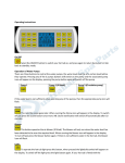
4GE Fiber Media Converter
User
’s Manual
User’
Introduction
Dear users:
Thank you for using the product of my company. In order to make your
work smoothly, we give you some advice. Before you connect and
operate the product, you should make sure to read this manual carefully
and pay more attention to the notices.
Safety Information
To avoid personal injury or the product and other products connected
with being damaged, you should be careful of the safety information.
Make sure use the product according to the rules to prevent the
occurrence of some potential harm.
Attention:
Power Voltage. The device can be only used in the area where the power
is AC 220V± 20%/50Hz. Please don’t use in other areas.
Use proper power line and power. You must use the power line equipped
with the products randomly. Also you can use other qualified power line
with case which can protect earth terminal. The earth terminal of the
outlet that is matched with power cord should be well ground
connection.
Attention ground connection. The product is grounded by the conductor
in the power line or terminal on the panel. To avoid electric shock, the
ground conductor of the power line must be grounded in a good
1
connection with the earth. Before you connect all the optical ports of the
product, you should be sure that the product is well grounded.
Take care of typical value of the ports. To avoid fire or electric shock,
please pay attention to all typical values and symbols labeled in the
equipment and this manual.
Don’t venture operation. When you doubt this product cannot work
properly, please consult our professionals instead of venturing operation.
Vibrations and Crash. This machine contains elaborate optical
component, you should avoid strenuous vibrations and crash.
Don’t open the cover of the machine and repair arbitrarily.
There aren’
t components for users to repair in the main case of this product. If you
need repair the product, please contact our company professionals. As
soon as you open the cover, you will have no warranty.
Cautions
The product is Class IIIB laser device product. There is the laser radiation
that your eyes cannot see in the machine. It is possible that the machine
will cause some physical damage of your eyes and skin if you operate it
improperly. After the machine powers up, you can’t look steadily at the
fiber optical input and output port or the fiber connector interface
connected with the ports.
2
Keep the fiber optical connector clean, or it will cause attenuation and
affect transmitting distance. When you install the product, you should
dip tidy cotton with absolute ethyl alcohol to clean it.
3. The product is sensitive to static electricity. Before you contact with
electric interface, you should release static electricity.
4. To prevent fire or electric shock, please don't let the product wet or
damp. Don't operate in damp conditions.
5. Don’t open the lid of the product to operate it.
6. Keep the surface clean and dry. You should ensure good ventilation
and heat-emission.
3
Product Overview
The device is Ethernet IEEE802.3 media transceiver to achieve media
conversion or extending network transmission distance between two
kinds of media, which are 10/100/1000Base-T UTP and 10/100/1000
Base-FX or 10/100/1000Base-T UTP and 10/100/1000 Base-FX. It mainly
used for fiber network far distance (20/40/60/80/120km) transmission,
supports 10/100M/1000M or 10M,100M,1000M trans-mission rate. Fiber
port and UTP can work through 10M、 100M 、1000Mrate.
Product Features
� Automatically adapt to 10M/100M/1000M environment, upgrade
network easily;
� Device provides 4 Ethernet interface, 1 Ethernet optical port
� Support full-duplex and half duplex network communication, with
auto-negotiation capability;
� The Ethernet interface supports jumbo frames (1916bit), which can
match with the switch product complied with IEEE802.10 protocol
� Support UTP cross connection switch optional, convenient for system
debugging and setup
� Division of VLAN base PORT, this method does not affect the remote
device
� 802.1Q VLAN Division, at this time, the local and the remote interface
can be divided into the same VALN
� Device provides Console port, supports Terminal control device
� Ethernet port priority setting
4
Parameters
� Fiber
Multi-mode Fiber
50/125um, 62.5/125um,
Maximum transmission distance: [email protected]/125um single mode fiber,
attenuation (3dbm/km)
Wave Length: 820nm
Transmitting power: -12dBm (Min) ~-9dBm (Max)
Receiver sensitivity: -28dBm (Min)
Link budget: 16dBm
Single-mode Fiber
8/125um, 9/125um
Maximum transmission distance: 40Km
Transmission distance: 40KM@9/125um single mode fiber, attenuation
(0.35dbm/km)
Wave Length: 1310nm
Transmitting power: -9dBm (Min) ~-8dBm (Max)
Receiver sensitivity: -27dBm (Min)
Link budget: 18dBm
�
Ethernet UTP Interface
Interface rate: 10/100/1000 M, half/full duplex auto-negotiation
5
Interface Standard:Compatible with IEEE 802.3, IEEE 802.1Q (VLAN)
MAC Address Capability:4096
Connector: RJ45, support AUTO-MDIX
� Electric Mechanic Features
Power Supply:
AC180V ~ 240V;DC –48V;DC +24V
Power Consumption:
Dimension:
≤5W
216(length) X 140(width) X31(height) mm
Weight: 1 Kg
�
Working environment
Working temperature:
-30℃—+75℃
Storage temperature: -40℃—+85℃
Working Humidity:
0%~95 % (no condensation)
MTBF: >100,000Hours
6
Panel Description
This desktop device has two types: Built-in power type and External
power type. The rack device can be optional.
Figure One.
Built-in power type device front panel
Figure Two. Desktop device back panel
Indicator LED
Name
Color Condition
Description
Device with 8 indicator lights, as follows
PWR
Green
ON
Power is on
OFF
Power is off
ON
LINK
Green
OFF
Flash
100M
Green
ON
OFF
LINK(R45)
Green
ON/Flash
Ethernet Optical Interface is on
Ethernet Optical Interface is off
Ethernet Optical Interface data be sent and
received
Ethernet Optical Interface 1000M
Ethernet Optical Interface 10/100M
1-4Channel Ethernet Optical Interface is on/
data be sent and received
7
OFF
ON
100M(R45)
Green
RUN
Green
1-4Channel Ethernet Optical Interface is off
1-4Channel Ethernet Optical Interface 1000M
1-4Channel Ethernet Optical Interface
10/100M
Device works normally
OFF
Flash
Ethernet Interface
1Channel Ethernet and 4Channel Ethernet can be optional. Support
10/100/1000M, half/full duplex auto- negotiation and AUTO-MDIX
(crossed line and straightly connected line self-adaptable)
LINK
Green ON
OFF
100M Green ON
OFF
Ethernet is connected
Ethernet is not connected
Ethernet rate is 1000M
Ethernet rate is 10/100M
RJ45 Connector and Crystal head PIN order as follows:
10/100/1000M Ethernet Interface
Crystal head PIN
order
�
Straightly connected line order
A end Crystal head PIN
B end crystal head PIN
PIN
Twisted Pair Color
PIN order
Twisted Pair Color
order
White and Orange
1
1
White and Orange
Orange
2
2
Orange
8
White and Green
3
3
White and Green
Blue
4
4
Blue
White and Blue
5
5
White and Blue
Green
6
6
Green
White and Brown
7
7
White and Brown
Brown
8
8
Brown
Crossed line order
�
A end Crystal head PIN
B end crystal head PIN
PIN
Twisted Pair Color
PIN order
Twisted Pair Color
order
White and Orange
1
1
White and Green
Orange
2
2
Green
White and Green
3
3
White and Orange
Blue
4
4
Blue
White and Blue
5
5
White and Blue
Green
6
6
Orange
White and Brown
7
7
White and Brown
Brown
8
8
Brown
Description:
Crossed line A end "1"
connects with "3"; A end "2"
connects with "6".When the connected Ethernet line is very long, you
should be sure that "1"and "2" "3"and"6"are a pair line of Twisted Pair.
9
Fiber Interface
Physical Interface: FC/SC (Optional), single-fiber and
dual-fiber (Optional).
Dual-Fiber:
TX-Transmit
RX-Receive
Single-Fiber: Transmit and Receive (Note: 1310nm and
1550nm device used in pair)
Power
Device supports AC220V, DC -48V and DC24V (Optional)
If you use AC220V power, you should connect device power input port
with power socket by using random power line to provide AC220V
power device.
If you use DC to supply power, DC-48V as an example, please connect as
follows:
General Connection
“FG” polarity
Connect ground
“DC-48V” polarity
“GND” polarity
Connect power negative polarity
Connect power positive polarity
Note: Device has polarity protection measures. If positive and
negative polarity is connected reversely, device will not damage,
function well and ease of installation and maintenance. (The power
contains DC48V, DC -48V, DC24V, DC -24V, and so on).
Console Interface
10
This is for PC hyper-terminal control.
Use DB9 cable to connect the PC's COM port with CONSOLE port;
Run the "hyper terminal" program under WINDOWS system,or run
other third-party serial port connection software, set the default
parameters as following:
Baud rate: 9600;
Data byte: 8;
parity check: none;
Stopbit: 1;
Flow control: none;
Press "ENTER" continuously for several times, enter system's CLI
interface and begin management work.
= PDH With 4chan Enthernet Control System V2.5 ==
Equipment Start-up................................
========================== Main Menu ========================
== 1.current Ethernet information,Please input '1'
== 2.current PDH & E1 information,Please input '2'
11
===
===
== 3.Enter config menu,Please input '3'
===
== 4.Language Switch(Chinese or English)!Please input '4' ===
=============================================================
[Future /]:
Attention: when DIP1-8 are ON, re-giving the power to the device will
clean all setting record, so be attention to do like this.
Submenu introduction
1. Check etherent setting information, input "1"
separate mode is:special channel separate
Information of separate set:
Havn't Set Separated!
Information of bandwidth:
UP PORT0:100M,00*32K
PORT1:100M,00*32K
PORT2:100M,00*32K
PORT3:100M,00*32K
PORT4:100M,00*32K
The device support packet sizes up to 1916!
PORT1:auto negotiation
PORT2:auto negotiation
PORT3:auto negotiation
PORT4:auto negotiation
UP PORT: MII,full duplex
802.1P Configration:
Disable 802.1P!
Pri-value: PORT1:0 PORT2:0 PORT3:0 PORT4:0
Press Any Key to Continue.....
2. Check PDH&E1 information,please input"2"
[Future /]:2
Mian and reserve fiber signal lost.
LOCAL/REMOTE Fiber alarm Status:
12
OLOS OLOF E3
E6
ALAR OK
OK OK
ALAR OK
OK OK
LOCAL/REMOTE E1 LOS alarm Status(L:LOS,I:Insert):
1 2 3 4 5 6 7 8 9 10 11 12 13 14 15 16
L L L L L L L L L L L L L L L L
I L L L I L L L I L L L I L L L
Hot line telephone on-hook.
Not Command the remote E1 Loop-Back.
Not Mask E1 Alarm.
Sound Alarm OFF.
Local fiber loop off.
Press Any Key to Continue.....
[Future /]:
3. Enter setting menu, please input "3"
[Future /]:3
=========================== Config Menu
===============================
== 1.Config bandwith of device,Please input '1'
== 2.Set Ethernet PHY port status,Please input '2'
== 3.Config 802.1P,Please input '3'
== 4.Config 802.1Q separate,Please input '4'
== 5.Config 802.1Q-switcher,Please input '5'
== 6.Config channel separate,Please input '6'
== 7.Change support packet sizes(1916 or 1936 ),Please input '7'
== Exit,Please input '0'
===
===
===
===
===
===
===
===
===================================================================
====
[Future /Config]:
3.1 Ethernet bandwidth setting, input "1"
[Future /Config]:1
=========================== Bandwidth Config =========================
== Set local bandwidth : setl m xyz ab (m: Port, xyz,ab: Value
===
== bandwidth =(x*100+y*10+z)M+32*(a*10+b)K (m<5,xyz<100,ab<32)
===
13
== Note:(1)If set Up-link bandwidth,than m=0;(Up-link is optic port)===
== Exit,Please input '0'
===
===================================================================
=
[Future /Bandwidth config]:
X,y,z respectively denote hundred's place, decade and unit for
a hundred number; a,b denote decade and unit for a ten number; m
means port number, when m=0 denote optical connector,
m=1/2/3/4 denote the 1st/2nd/3rd/4th ethernet port.
If you want to set the 3rd ethernet bandwidth is 55M+32*16K,
then input setl 3 055 16
3.2 Ethernet 10/100M setting, input "2"
[F uture /Config]:2
======================== Port Status Config ===========================
== Set command : set x y
===
==
===
== Note: x:Port numble(0<x<=5,5:UP PORT) y: 0 auto negotiation
===
==
1 fored half duplex and 10BT ===
==
2 fored full duplex and 10BT ===
==
3 fored half duplex and 100BT===
==
4 fored full duplex and 100BT===
==
===
== Exit,Please input '0'
===
===================================================================
====
[Future /Port Status Config]:
3.3 802.1P setting,input"3"
[Future /Config]:3
========================= 802.1P Config
==============================
== 1.Enable or disable 802.1P
== 802.1P user-priority command: set x y
14
===
===
==
== Note: x:port number(0<x<=5,5:optic port) y: value(0=<y<8)
== (using this value when receive-packets havn't tag)
==
== Exit,Please input '0'
===
===
===
===
===
==============================================================
=========
[Future /802.1P Config]:
Mark: X means 1-4ch etherent port.
Y means priority grade,including:
� The highest grade is 7,applied in critical network traffic, such as
routing choose information protocol(RIP) and open shortest
path(OSPF) protocol's routing table update;
� Priority 6 and 5 mainly apply in delay-sensitive program, such
as interactive video and audio;
� Priority 4 to 1 mainly apply in controlled-load program, such as
streaming multimedia and business-critical traffic;
� Priority 0 is default value, and start automatically without setting
other priority grade.
Attention: when ethernet packet is with tag, the device will dedicate
priority grade automaticly by tag; otherwise, use setting x y to set
priority grade by real situation.
3.4 set based on 802.1Q, input"4"
[Future /Config]:4
====================== 802.1Q Separate Config =========================
== 802.1Q Separate set : setl x y
===
15
==
===
== Note: x:vlan enable(1:enable,0:disable) y: Separate modes(y = 1) ===
== Explanation of 802.1Q separate mode :
===
== Mode1(CH1:Port1;CH2:Port2;CH3:Port3;CH4:Port4)
===
==
===
== Exit,Please input '0'
===
===================================================================
====
[Future /802.1Q Separate Config]:
3.5 802.1Q switch setting, input "5"
[F uture /Config]:5
====================== 802.1Q-switcher Config =========================
== Note:You can choice one of 3,4,5,and 3,4 used for back-to-back ===
==
===
== 1.Enable or disable 802.1Q
===
== 2.PVID config(add this tag if packets no tag): set pvid x yyyy ===
== Note: x:ports number(0<x<=5,5:optic port) yyyy:VID(0=<y<4096) ===
== (disable tag insertion when yyyy = 0)
===
== 3.802.1Q vlan-id config command: set vid xx yyyy
===
== Note: xx:No(0=<xx<16) yyyy:VID(0=<y<4096)
===
== 4.802.1Q membership config command: set/clr port xx y
===
== Note: xx:No(0=<xx<16) y:ports number(0<y<=5,5:optic port)
===
== e.g:vlan1:port1-3,vid=2; vlan2:port4-5,vid=3;
===
== set vid 00 0002;set vid 01 0003;set port 00 1;set port 00 2; ===
== set port 00 3;;set port 01 4;set port 01 5;
===
== 5.Clear vid and memberships,Please input '5'
===
== 6.Loop up current switcher information,Please input '6'
===
==
===
== Exit,Please input '0'
===
===================================================================
====
[Future /802.1Q-switcher Config]:
3.6 channel separating setting, input"6"
16
[Future /Config]:6
======================== Channel Separate Config ======================
== Channel Separate set : setl x y
===
==
===
== Note: x:Channel Separate kinds ( 0=<x<4 )
===
==
y:Channel Separate modes(0<y<5)
===
== Explanation of Channel Separate Kind :
===
== Kind0( x=0 ) : Disenable Channel Separate
===
== Kind1( x=1 ) : Corresponding Channel Separated,and untagged
===
== Kind2( x=2 ) : Corresponding Channel Separated,and tagged
===
== Kind3( x=3 ) : Channel separated at local device
===
== Explanation of channel separate mode :
===
== Mode1(CH1:Port1;CH2:Port2;CH3:Port3;CH4:Port4)
===
== Mode2(CH1:Port1,Port2;CH2:Port3,Port4)
(For Kind3(x=3) only) ===
== Mode3(CH1:Port1,Port2;CH2:Port3;CH3:Port4)(For Kind3(x=3) only) ===
== Mode4(CH1:Port1;CH2:Port2,Port3,Port4)
(For Kind3(x=3) only) ===
==
===
== Exit,Please input '0'
===
===================================================================
====
[Future /Channel separate config]:
Channel types instruction:
Type 0, when x=0, means cancel channel isolation;
Type 1, when x=1, means corresponding channel isolated, but the
data has no label;
Type 2, when x=2, means corresponding channel isolated, but the
data has label;
Type 3, when x=3,means the local device's ethernet channels all
isolated to each other.
Attention: in ethernet transmission, the data packet is no need to
add label. But in some special network, need to add label to
17
enhance network transmission safety.
Channel isolation instruction:
Mode 1: each channel isolates to each other;
Mode 2: consider 1st and 2nd etherent as one transmission
channel,3th and 4th ethernet as another transmission channel;
Mode 3:consider 1st and 2nd etherent as one transmission
channel,3th ethernet as one channel,4th ethernet as another
channel;
Mode 4: consider 1st ethernet as one channel,the other three
etherent as one channel.
Attention: except mode 1, the other mode can only be applied in
type 3, which is setting in local device only.
3.7 Ethernet packet switch between 1536 and 1916, input "7
[Future /Config]:7
Accept packet sizes form 1916 bytes to 1536 bytes!
=========================== Config Menu
===============================
== 1.Config bandwith of device,Please input '1'
== 2.Set Ethernet PHY port status,Please input '2'
== 3.Config 802.1P,Please input '3'
== 4.Config 802.1Q separate,Please input '4'
== 5.Config 802.1Q-switcher,Please input '5'
== 6.Config channel separate,Please input '6'
== 7.Change support packet sizes(1916 or 1936 ),Please input '7'
== Exit,Please input '0'
===
===
===
===
===
===
===
===
===================================================================
====
18
[Future /Config]:
The device has two types of packet:1916 and 1538, each ethernt
port should be setted unified.
4. Chinese and english swtch,input "4"
[Future /]:4
切换成功!
================= 主菜单 ==================
== 1.查询以太网设置信息,请输入'1'
== 2.查询PDH & E1 信息,请输入'2'
===
===
== 3.进入设置菜单,请输入'3'
===
== 4.中英文切换,请输入'4'
===
===========================================
[Future /]:
After-sales Service
The series of our Fiber Media Converter products, our company promises
one-year warranty. During product warranty time, our company provides
free repair service, but if the following cases, we will charge the cost of
materials.
1. Damage due to not complying with the manual.
2. Tear down the device without authorization, which leads to bad
situations.
3. Lightning, fire and inevitable natural disasters.
19
4. Our products don’t match with other company products because of
bad design to cause damage.
Company Statement
1. As we are adopting new technology, if our product technical
parameters are changed, we won’t notice you.
2. The final interpretation right of this manual belongs to my company.
20