1
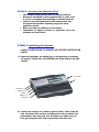
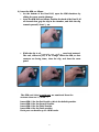
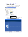
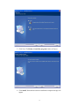
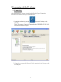
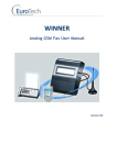
WINNER GSM Dual Channel Fixed Cellular Terminal USER’S MANUAL WINNER, GSM 900 /1800 MHz, 800/1900 MHz SIM cards and Wavecom Module embedded Double Fixed Cellular Gateway Units VERSION V 5.2 Last updated: 17/07/08 1 Dear Customer: Thank you for purchasing one of our WINNER GSM single/dual channel fixed cellular terminals. The information in this manual does not constitute a warranty of performance, although the information has been compiled and checked for accuracy by Eurote ch Communication Ltd. All our products are developed and pr oduced by an experienced staff, who aspire to achieve customer satisfaction, utility value, quality and reliability of products. Eurotech Communication Ltd. reserves the right to update this publ ication without notice. Trademarks: EUROTECH is a registered trademark. Warranty policy: The WINNER GSM Fixed Cellular Terminal you have purchased is under warranty for a year from the date of purchase by original purchaser. In case of defects in material s or workmanship Eurotech Communication Ltd. will replace free of charge. This warranty applies to hardware/ software and does not include SIM cards. This warranty will not be honored if the device has been mishandled in any way. Approvals: The WINNER G SM gateway products are approved for connection to telecommunications services via a PBX, telephone line or even a personal extension. all ISO 9001: 2008 approved, they also feature a modern user -friendly design, provide maximum control and economy of op eration and aid in radiation prevention. This unit should only be serviced by authorized service persons. For any assistance (technical assistance or repair) call: +972 -4-6801080. 2 TABLE OF CONTENTS General Overview 4 Packing List 5 Safety Guidelines 5 Quick Start Guide 6 General Information 7 Interference with Medical and Personal Electronic Devices 7 Antenna Considerations 7 Installation Steps and Procedures 7 STAGE STAGE STAGE STAGE STAGE 8 9 9 12 21 1: Identifying potential sources of interference 2: Assessing the subscriber site 3: Installing the system 4: PC Programming Management. 5: Testing General Technical Information 21 Telephone Characteristics 21 3 Instructor’s note: The following instructions will introduce you to the Winner GSM fixed cellular terminal you have purchased and to the installation and management software. To understand these instructions you need to have basic familiarity with Microsoft Windows (any version). Overview This user’s manual will help you best install your WINNER GSM gateway unit, and provide you with the basic guidelines for handling any problems that might arise. In general, the WINNER GSM single/dual gateways provide a flexible and cost efficient connection between your telephone system and the GSM mobile networks. In essence the device acts as a router that is programmed to choose the Least Cost Route when you make a call from your PSTN line to a cellular phone. The GSM gateway connects to a trunk line and bypasses the telephone company thus significantly reducing overhead costs of telephone calls. Connect to your PBX or landline phone or even to a specific phone extension (special order), and you will save money on all calls by bypassing the telephone n etwork and obtaining direct access to the GSM networks. The embedded Wavecom Module and SIM cards which act as 'Smart' user ID cards that encrypt voice and data transmissions and store data concerning the specific user and personal phone settings, make the GSM gateway a cell phone in itself. The WINNER gateways are therefore an essential tool for cutting overhead costs of telephone bills as they allow direct access to the GSM networks and cut costs of airtime and interconnections. The WINNER GSM gatewa ys are intended for medium to large enterprises but can be installed on regular phone lines in your home or home office. There are certain features that may be relevant to the product you have selected and some that are not. However, all are discussed in the following manual. The WINNER GSM single/ dual channel units, when used with the appropriate telephone equipment (antenna, adapter, SIM cards, telephone PSTN line or PBX) will function as an ordinary landline and support the following features: Cost-saving routing of incoming calls GSM and PSTN interconnection via internal LCR Caller ID, LCD, RTC. Fax, Data, SMS Transmission – Optional Internal Battery Backup. FXS interface Polarity Reverse Outstanding voice performance and echo cancellation 4 The WINNER - GSM Dual Channel Gateway unit: main features and benefits: o Is able to use up to 8 SIMs (up to four SIM cards per GSM channel enabling two outgoing simultaneous calls to any four operators). Packing List: On receiving your WINNER device, please insp ect the package to verify that you have the following: 1. One WINNER GSM dual channel gateway unit . 2. 12V Power Supply Adapter. 3. Antenna for each port. 5. RJ-45 10 pin RS-232 cable. 7. Screws & wall plugs. 8. Software Installation CD. Safety Guidelines: For the safe and efficient operation of your WINNER gateway unit, please observe the following guidelines: Before installing the unit, please read the installation instructions and safety guidelines in this User's Manual carefully. Do not handle the equipment before disconnecting it from the electrical outlet. Do not use any cleaning agents or detergents on the exterior or interior surfaces. If you intend to clean the device, disconnect from electrical outlet and use only a damp cloth. Do not position device in a damp place; do not expose to water. Do not expose to extreme temperatures: optimal operating temperatures -5° C to +50°C. Position equipment in a stable environment; any sudden fall or sharp movement may damage the device. Do not cover or stick any foreign objects over device openings or ventilation holes. Do not operate your WINNER device while any person is within 0.02m of the antenna. A person or object within 0.02 m of the antenna could impair call quality and may cause the phone to operate at a higher power level than necessary. Warning: Potential Explosive Atmospheres: Do not operate your WINNER near blasting caps, or in a blasting area, to avoid the possibility of triggering an explosion. Do not operate a WINNER transmitter in a hazardous atmosphere: an explosion or fire may result. The telephone interface is not designed for outdoor application: RJ-11 cable must not be run to an outdoor telephone; this minimizes equipment exposure to coupling and direct lightning surges. 5 Quick Start Guide ALWAYS POWER-DOWN The WINNER UNIT BEFORE INSERTING SIM CARDS General 1. 2. 3. 4. 5. 6. Check package contents. Insert Sim cards. Connect the antenna/s. Connect the unit to analog telephone s – one for each port. Connect the power supply and wait 30 secs. LCD displays: [State:Voice …….Antenna reception bargraph]. For each Port 7. Check antenna reception. If reception is poor, disconnect the power and change the antenna location. Repower the system and wait 30 secs. 8. Place an outgoing call – dialled number is displayed. 9. Place an incoming call to the unit – incoming number is displayed. 10. Disconnect the analog telephone and reconnect the u nit to your PBX line. Programming the Winner Gateway unit 1. Install the CD launch program on the computer. 2. Connect the RJ-45 Plug of the com cable to one of the ports (Master or Slave). Connect the D -type connector to an available COM outlet on the PC. 3. The display will show "Init. COM port". 4. Start the "Winner v5.2" from the icon on your desktop. 5. Press the "Connect" icon at the top left-hand corner of the window. 6. Choose the correct PC comport from the drop down list. 7. Click the "System" icon and set the Rea l Time Clock in the unit. 8. Click the "Port Setting" icon to change the general port parameters and click the "Write Settings" button to update the unit before moving on. 9. Click the "Prefix Settings" icon and write the prefixes and tariffs for each Sim. 10. Press the "Disconnect" icon. 11. Connect the RJ-45 plug of the programming cable to the other port (if needed) and retrace steps 2 to 10. 12. Click the "Exit" icon to close the Launch window. 15. Disconnect the programming cable. 6 General user information: Placement of the device: the WINNER GSM gateway unit is designed for installation on a vertical surface but may also be mounted on a wall. If you wish to mount the device on a wall follow these steps: 1. Remove the metallic strip used for hanging th e unit on the wall by sliding it out from the back of the WIN NER unit and place the metallic strip on the wall to indicate the location of the screws. 2. Hold the strip on the wall and drill holes for the screws to go into the wall through the metallic strip. 3. Place the unit onto the wall by sliding the metallic strip back into place. Interference to Medical and Personal Electronic Devices Most electronic equipment is shielded from RF energy. Nevertheless, RF energy from the WINNER transmitter may a ffect inadequately shielded electronic equipment. We therefore advise to consult the manufacturer(s) of your medical and personal electronic device(s), (for example a pacemaker or hearing aid) to determine if they are adequately shielded from external RF energy. Do not install a WINNER gateway unit in a health care facility, if regulations posted in the area restrict the use of cellular phones. Hospitals and health care facilities may be using equipment that is sensitive to external RF energy. Antenna Considerations: Use only the supplied or approved antenna. An unauthorized antenna, modifications or attachments could affect call quality. 7 Installation STAGES and Procedures The installation procedure consists of the following steps: STAGE 1: Identifying potential sources of interference. STAGE 2: Assessing the subscriber site. STAGE 3: Installing the system – please note differences in single/ dual channel units. STAGE 4: PC Programming Management. STAGE 5: Testing. STAGE 1: Identifying Potential Sources of Interference The electronic circuitry of some telephones may be insufficiently shielded to operate properly with the WINNER gateway units. When making or receiving a phone call, if you hear a “humming” sound or noise in the earpiece of the telephone connected to the WINNER, or if any other party hears the hum or noise, move the telephone away from the WINNER. If moving it farther away has no effect, try using a different telephone. The WINNER is a two-way radio and as such, some occasional interference is unavoidable. For best results, choose an electrical outlet away from obstructions. Do not place the WINNER near items, which may increase, static, such as: Electrical appliances Lamps Microwaves TVs Fax Machines 4 Feet (1.2 meters) Computers 4 Feet (1.2 meters) Refrigerator Vacuum cleaner Light dimmers Fluorescent bulbs Motors Fans 8 STAGE 2: Assessing the Subscriber Site The WINNER GSM gateway must be installed indoors. Basement installation is not recommen ded, in some cases it can be accomplished by installing an external antenna. Install in an environment where the temperatures may not exceed the specified operating range (see safety guidelines above). Make sure there is sufficient air circulation. Installation in higher locations is preferable, also near windows and outer walls. STAGE 3: Installing the System : ALWAYS POWER-DOWN The WINNER UNIT BEFORE INSERTING SIM CARDS! 1) Inspect the package, you should see: a unit gateway, an antenna, an adapter. Please note: the WINNER unit comes without the SIM card(s)! Antennas Com Port 2 PBX Line 2 Power PBX Line 1 Com Port 1 2) Connect the antenna at a distance greater than 1 meter f rom the unit. Location of the antenna is important in order to obtain best performance, thus once you turn the power on, make sure you have good reception and clear conversation with the unit.* 9 3) Insert the SIMs as follows: On the bottom of the Dual Cell, open the SIM chambers by sliding the cover panels sideways. Open the SIM slots as follows: Position the back of the Dual C ell as shown below, grip the clip in the chamber, and slide the clip towards yourself, about ¼ cm. While the clip is slid towards you, pull it upward and outward. The end, closest to you, is on a hinge. Insert the SIM, so that contacts are facing down, close the clip, and close the cover panel. The SIM card slots in each port are numbered from the antenna down as #1, to #4. ** Insert SIM #1 for the first Provider, this is the default provider. Insert SIM #2 for the Second Provider. Insert SIM #3 for the Third Provider Insert SIM #4 for the Forth provider Each port can handle up to 4 S IM cards. 10 4) Connect an ordinary analog telephone line with the RJ-11 cable to the socket on left side panel of the gateway unit. 5) On the left side panel you will find the PO WER socket. Connect the adapter (provided with unit) to the mains outlet and then to the socket on the unit. Note: The power input is 90 –260 VAC and the output is 12 VDC 1.2 Amp 6) Wait 30 seconds for the unit to s tartup. Testing: When you see the operator/ provider name on the LCD try to make an outgoing call, you should see the number dialed. Make a call to the unit from a remote telephone, ce llular or landline, the caller ID should appear on the LCD. Notes: * Antenna reception: After Sim insertion, antenna connection and power-up, the LCD will display antenna reception power in the form of a BarGraph. Make sure you have as much reception power as possible, by moving the antenna to different locations. ** A dual gateway unit has 2 ports. The MASTER port (Port1) at the lower portion of the unit and the SLAVE port (Port2) at the upper portion. Each port has it's own module and antenna socket. The two ports are basically independent but the Master port controls the RTC (Real Time Clock) and the LCD display. ALWAYS POWER-DOWN The WINNER UNIT BEFORE INSERTING SIM CARDS! 11 STAGE 4: PC Programming Management. 1. Installing the PC Software 1. Insert the Winner 5.2 Installation CD into to CD drive of the PC. 2. In Windows Explorer, navigate to the installation CD drive. 3. Double click on to install the Winner 5.2 PC Manegment Software. The installation Window will open. 4. Click Next, The Setup Type window will open. 12 5. Click Next, The Ready to install the program window will open. 6. Click install, Wait until the software installation complete message will appear. 13 2. Programming with the PC software 1. Connecting After installing the PC software, launch it and define the Type of Connection between the PC and the Gateway as described below. 1. Launch the software by pressing on your PC desktop, or by pressing: Start > Programs > Eurotech -Communication >WINNER V5.2 W-3.6.2. The software window will open. 2. Connect the com port cable from the Com1 connection in the Gateway to the PC Com port. 14 3. Press in the toolbar. The connection window will open. 4. Select the Com Port in the PC the gateway is connected to. 5. Press OK to connect. 6. At the bottom of the window you will see the connection status. When connected you see the status Connected and one of the led image on the bottom-right will be green. 7. The Time: is the time and date the gateway is set to. 8. The Gateway Ver: is the firmware program version of the gateway. 9. The Bootluader Ver: is the bootluader program version . 10. The Gateway Mode: is the connected port type (Master or Slave) . 15 2. Port Settings 1. Press to configure the port. 2. Select in the LCR the operation mode of the gateway: Disable – All calls will go out and in using SIM #1. Prefixes – The calls will go out according the prefix of the dialed number. The call will go out with the first SIM from 1 to 4 that have the prefix in his prefixes table. Day of the Week – The SIMs will rotate every set number of minutes. Select the Day and enter in Min the number of minutes a SIM will work before rotating to the next the SIM in that day. Press Write Settings. Repeat this to set the timers for every day. Day of the Week + Prefix – The SIMs will rotate every set number of minutes but the call will go out only if the prefix is in the current SIM prefix table. SIM Times – The gateway will count the calls minutes. When the count, at the end of a call, will reach the SIM Timer (in the Prefixes Settings) the gateway will switch to the next available SIM. At the end of all the available SIMs the gateway will go to sleep (constant busy tone) until the Reset Date when all counter will reset. SIM Times + Prefix – The same as SIM Times but the call will go out only if the prefix is in the current SIM prefix table . 16 3. Select in the Incoming Call enable to allow receiving of incoming calls from the cellular network. 4. Select in Dial Tone a matching dial tone to your countr y. 5. Select in Ignore First Digit the digit to ignore when appears in the beginning of the number. Disable – No digit will be ignored. Any – Any first digit will be ignored. Three – The first 3 digits will be ignored. 6. Select in the Answer Supervision the line power at the call. The options are : Disable – No answer supervision. Battery Reversal – Reversing the power of the line in the time of the call. Double Line Rev – Reversing the power of the line again at the end of the call. Break Line – No power in the line at the end of the call. 7. Select in the Answer Supervision Timer the time to do the Double Line Rev and Break Line in 0.1 seconds units. 8. Select in the Inter Digits Timer the time between the last digit dialed and sending the number. 9. Select the Minimum Digits Dialed for a valid number. 10. Select the Maximum Digits Dialed for a valid number. 11. Select On in the Data Mode to send and receive data through the module. Select Off to work in voice mode. 12. Select On in the Setup CID to generate caller ID to the FXS line. 13. Select the Call Meter operation mode: Disable – No call meter. By Tariff – The call meter pulses start at the beginning of the call . By Answer –The call meter pulses start at the answer to the call . 14. Select On in the Comfort Tone to generate a tone when switching SIMs. 15. Enter in the Predialing the digits to be added at the beginning of the dialed number. 16. Enter the Base Tariff when working with call meter (see Tariffs in the Prefixes Setting). 17. Select in the RX Volume the volume of the speaker in the PBX. 18. Select in the TX Volume the volume of the microphone from the PBX. 17 3. Prefixes Setting 1. Press to configure the SIMs settings and prefixes. 2. Select the SIM you want to change the prefixes. 3. Enter the prefixes of the Selected SIM . There could be up to 32 prefixes per SIM. Each prefix could be between 1 to 10 digits. 4. Select in the CLIR when to send the SIM Caller ID: By Network – The GSM Network decide. CLIR Invocation – The gateway don’t send Caller ID. CLIR Suppression - The gateway send Caller ID. 5. Select in the Network specific network for the SIM to work with. 6. Enter the PIN Code of the SIM (Needed only when the SIM demand a PIN Code). 7. Enter in SIM Timer the calls minutes the SIM will work (in the SIM Times LCR Mode). 8. Press the Write Prefixes button to save changes. 18 Tariffs: Billing By Pulses per minute Billing sum is based on the number of pulses counted during a conversation. "No. of pulses" can be separately programmed for each SIM Prefix. To set the tariffs press the Tariffs button. This is how it is done: 1. A "Base Tariff" for all Sims is entered in the appropriate place in the "Port Setting" screen. This can be any whole number. 2. Enter a tariff for each SIM Prefix, Press Write Tariffs. These numbers are divided by the base-tariff to get the pulses per minute. Example: Base-Tariff is set to 4 Sim1 prefix1 is set to 20. Pulses per minute = 20/4 = 5ppm. (1 pulse every 12 sec onds) 3. Set "Call Meter" to "by tariff". 4. A 16KHz counter has to be attached to the telephone line, in o rder to utilize the By-Tariff option. 19 3. System Setting Press button to set the time of the gateway. Changing the Time and Date 1. Press the Date Box and then change the date of the gateway. You can press the drop button to select the date fr om a calendar. The Day of that date will appear. 2. Mark each number in the Time box and press the buttons to change the time of the gateway. Backup and Restore of the Setting 1. Press the Backup Data to File Button and choose a file to store all the setting s of this port. 2. Press the Restore Data from File Button and choose a file to restore all the settings of this port from a file. 20 STAGE 5: Testing. With multiple SIMs: Make a call to each provider and watch the call progress on the LCD, You should see th e provider’s name and the dialed number, if all works 'OK' then you are done. General Technical Information Electrical Power supply: 12 VDC +/ - 5% 1,2 A 720 mA average in GSM 900 at Tx power max 2W 920 mA average in GSM/GRPS 900 at Tx power max 2W 100 mA in idle mode Physical Absolute maximum dimension: 165 x 127 x 30 mm Weight: 600 g Casing: Complete shielding-stainless steel Mounting: 4 screw holes Operating temperature range: -5°C to + 55°C Optimal storage temperature: -35°C to +85°C Analog Telephone/Analog PBX interface Tip/Ring Voltage –48V Line current 25ma Ringing Voltage 140 Vpp Load 3REN Crest Factor 1.25 Frequency 20 Hz Cadency 2s/4s Answer supervision - Reverse polarity DTMF compliancy Dial Tone 400 Hz Busy Tone 400 Hz, cadency 500ms/500ms GSM circuit Data Features Data circuit asynchronous, transparent and non transparent up to 14,400 b/s Automatic fax group 3 (Class 1 & 2 & 3) Alternate speech and fax MNP2, V.42bis Telephone Line Characteristics DC Characteristics Ringing voltage: On hook voltage: Off hook voltage: Off hook Loop current: resistive Input Impedance: typical -70 V DC typical -58 V DC typical -24 V DC typical 27mA @ 600 Ohm programming 480 Ohms to 720 Ohms, 600 Ohm 21 DTMF Dialing: Detection level: On time: Off time: Ringing Signal: Feeding type: Distortion: Ring drive capability Minimum ring Voltage: Frequency: Normal Dialing Tone: Frequency: Level: Cadence: Congestion / Busy Tone: Frequency: Level: 2dB Cadence: 500ms 20% pause -25dBm to +3dBm 50msec. 12 characters Balanced signal Less than 5% 3 type A 40 Vrms – crest factor 1.2 (20 Hz) 400Hz 2dB 400Hz 500ms 20% signal Environmental Characteristics Compliance: The WINNER complies with the following requirements: Temperature We claim -5° to 70° (Approved By Israeli Standard Institute) . Humidity 5% to 95% Safety (Approved By Israeli Standard Institute) Packing Per EuroTech standard Transportation Transport conditions are according to Euortech Standards. Storage Conditions Storage conditions are according to class 1.1, EST. 300 019 – 1-1 (-20°C +80°C) -25°C to +65°C 22