1
49
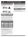
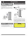
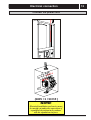
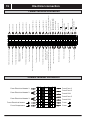
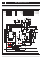
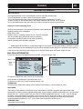
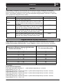
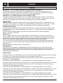
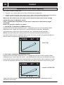
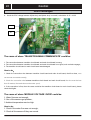
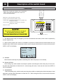
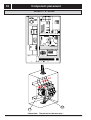
Description of the switch board
Connect to
common Terminal (CT)
When test or repair the machine, the compressor,
water cycle pump and outdoor fan motor can
be force manual startup.
Connect to WTP1
Connect to
common Terminal (CT)
Function
Water Pump : Control the Water Cycle Pump
E-Heater : Control the Electrical Heater 1 and 2
O-Warm Water : Control the 3 way valve turn to the Water Tank
Heating side ( B side )
WARNING !
THE SWITCH BOARD IS FOR EMERGENCY ONLY,
AND MUST BE OPERATED BY SERVICE ENGINEER ONLY!
I-Room Heating : Control the 3 way valve turn to the Room
NORMAL
Heating side ( A side )
Reserved : Invalid
ROOM HEATING
WATER
PUMP
NOTE!
E- HEATER
O - WARM
WATER
RESERVED
WARM WATER
I - ROOM
HEATING
The manual switch board is use only if
the necessary for test or repair.
When the heat pump is running normally,
the switch board must be in normal state.
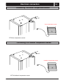
Connect to the PCB 2 ( CN1 L-IN)
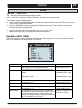
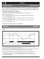
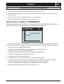
1˖The switch board is only for emergency, such as circuit boards were broken; and it must be operated by
service engineer only.
2˖When control systems are normal, it is forbidden to operate the switch board; the switch boards are only
available when circuit board or compressor broken; before using the switch board, it must set and ensure the
,
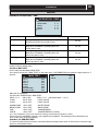
OPER. is OFF at the display.
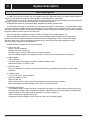
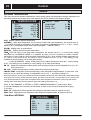
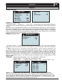
ROOM
20
MONDAY
11:30
OPER.OFF
1
HDO
CSP
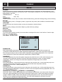
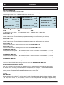
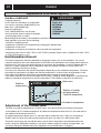
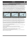
A> NORMAL:
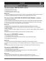
switch boards must keep the position as drawing then allow heat pump to runs normally.
B> ROOM HEATING:
room heating only; switch boards must keep the position as drawing then allow heat pump to heat room,
the feed water temperature is fixed with 40ć; before using this mode, it must set and ensure the OPER. is
OFF at the display .
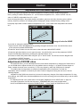
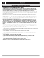
C> WARMEATER:
water tank heating only; switch boards must keep the position as drawing then allow heat pump to heat
water tank, the feed water temperature is fixed with 70ć; before using this mode, it must set and ensure the
OPER. is OFF at the display.