1
Vulture: User Manual
49
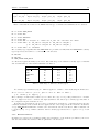
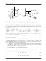
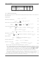
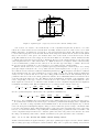
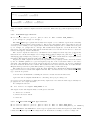
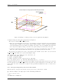
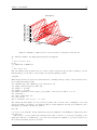
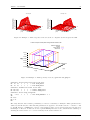
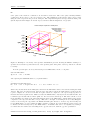
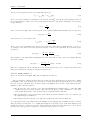
and the output from gvulture looks exactly like the free-space example is Figure 12. We have also chosen
to use PML absorbing boundaries on the open ends of the waveguide rather than the Mur ABCs used in
Example 1.
1.2
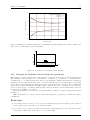
Electric field, Ez(10,20,10) (V/m)
1
0.8
0.6
0.4
0.2
0
-0.2
0
100
200
300
400
Time (ns)
500
600
700
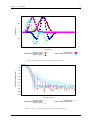
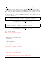
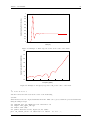
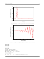
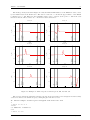
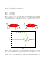
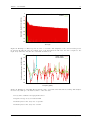
Figure 15: Example 2 - Time response for Ez at the centre of the mesh.
2
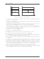
Electric field, |Ez|(10,20,10) (dB V/m)
1.8
1.6
1.4
1.2
1
0.8
0.6
0.4
0.2
0
-0.2
0
10
20
30
Frequency (MHz)
40
50
60
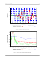
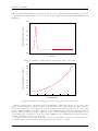
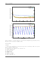
Figure 16: Example 2 - Frequency response for Ez at the centre of the mesh.
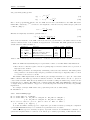
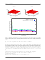
The processing steps are exactly the same as for Example 1. The time response at the centre of the
mesh is shown in Figure 15 and the frequency spectrum at the smae point in Figure 15. The “spurious”
reflections from the edge of the mesh in the previous example have now disappeared since the source plane
is now consistent with the boundary conditions on the external surfaces of the mesh. The DC response
has also disappeared since the charge on the source plane edges can discharge into the PEC plates. A soft
electric field source can therefore excite an accutate TEM wave in a parallel-plate waveguide structure,
however, it launches a wave in both directions!
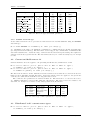
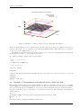
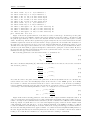
The time response of the electric field can be extract from the binary observer over a whole plane. To
accomplish this for time-step number 60 modify the process.dat file to contain
I. D. Flintoft
University of York