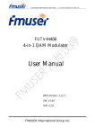
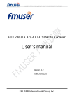
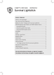
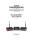
1
FMUSER INTERNATIONAL GROUP INC. 广州市汉婷生物技术开发有限公司
HD Portable Digital Video Wireless
FUTV-7132H Transmitter and Mobile
Digital FUTV-2009HIA Receiver
User Manual
HD Portable Digital Video Wireless Transmitter Version: FUTV-7132H
Mobile Digital Receiver Version: FUTV-2009HIA
Web NMS version: 2.00
Date: JULY, 2013
FMUSER International Group Inc.
FMUSER INTERNATIONAL GROUP INC. 广州市汉婷生物技术开发有限公司
About This Manual
Intended Audience
This user manual has been written to help people who have to use, to integrate and to
install the product. Some chapters require some prerequisite knowledge in electronics
and especially in broadcast technologies and standards.
Disclaimer
No part of this document may be reproduced in any form without
the written
permission of the copyright owner.
The contents of this document are subject to revision without notice due to continued
progress in methodology, design and manufacturing. FMUSER shall have no liability for
any error or damage of any kind resulting from the use of this document.
Copy Warning
This document includes some confidential information. Its usage is limited to the
owners of the product that it is relevant to. It cannot be copied, modified, or
translated in another language without prior written authorization from FMUSER.
1 / 36
FMUSER INTERNATIONAL GROUP INC. 广州市汉婷生物技术开发有限公司
Directory
Chapter 1 Introduction ...................................................................................................................................... 3
1.1 Product Overview.................................................................................................................................................... 3
1.2 Appearance and Descriptions (Mobile Receiver).................................................................................................... 4
1.3 Appearance and Descriptions (Portable Wireless Transmitter) ............................................................................. 7
Chapter 2 Installation Guide ........................................................................................................................... 10
2.1 Acquisition Check .................................................................................................................................................. 10
2.2 Installation Preparation ........................................................................................................................................ 10
2.3 Transmitter Installation......................................................................................................................................... 11
2.4 Receiver installation .............................................................................................................................................. 12
2.5 Wire’s Connection ................................................................................................................................................. 12
Chapter 3 Operation......................................................................................................................................... 16
3.1 Operation of Transmitter ...................................................................................................................................... 16
3.2 Operation of Receiver ........................................................................................................................................... 17
Chapter 4 Failure Clearing .............................................................................................................................. 34
Chapter 5 Packing List ..................................................................................................................................... 36
2 / 36
FMUSER INTERNATIONAL GROUP INC. 广州市汉婷生物技术开发有限公司
Chapter 1 Introduction
1.1 Product Overview
The wireless digital image transmission system (which comprises the wireless
transmitter and receiver) adopts the advanced COFDM modulation technology and the
channel codes and combines with MPEG4 AVC/H.264 digital image compression
multimedia network transmission technology. In addition to high-speed movement and
non-line of sight, it
can achieve the real time and synchronous transmission of
broadband multimedia services such as Video, Audio, data and etc. The system has
features of flexible structure, wide coverage, good mobility, strong ability to combat
interference and fading.
It is an ideal solution for providing long distance, high quality and high efficiency of
wireless real-time transmission applied in emergency telecommunications such as
commanding, emergency rescues, and multiple fields like investigation,
public security, armed police, fire control, oil
field, mines, water
field battle,
project, electricity,
and so on.
3 / 36
FMUSER INTERNATIONAL GROUP INC. 广州市汉婷生物技术开发有限公司
1.2 Appearance and Descriptions (Mobile Receiver)
l
The Front Panel Illustration of Receiver
4 / 36
FMUSER INTERNATIONAL GROUP INC. 广州市汉婷生物技术开发有限公司
l
The Rear Panel Illustration of Receiver
l
Key Features
ü
convenient and efficient network transmission
ü
dual LNB input
ü
real-time LED monitor for decoded program
ü
multi Audio/Video format output: 1*HDMI, 2*CVBS, 1*YPbPr, 1*HD-SDI
ü
multiple video resolution: 576i/480i, 576p/480p, 720p and 1080i decoding
ü
Support ASI input and output, IP input and output
ü
Support Keyboard and LCD operation
ü
web NMS management via Ethernet port
5 / 36
FMUSER INTERNATIONAL GROUP INC. 广州市汉婷生物技术开发有限公司
l
Technical Specifications
6 / 36
FMUSER INTERNATIONAL GROUP INC. 广州市汉婷生物技术开发有限公司
l
Principle Chart
1.3 Appearance and Descriptions (Portable Wireless Transmitter)
Antenna Connector
TS-Lock Indicator
Power Supply
HDMI in Connector
DC in/out
YPbPr + S-Video + AV Adapter Cable
Power Switch
7 / 36
FMUSER INTERNATIONAL GROUP INC. 广州市汉婷生物技术开发有限公司
l
Key Features
ü
Unfixed spot positioning transmitting of remote distance
ü
It can transmit close-distance, continuous, and moving (non-vision distance)
real-time AV signal.
ü
Adjustable transmitting power (0-3 W) and frequency (200-900 MHz)
ü
Adjustable modulating mode (QPSK/16QAM/64QAM)
ü
The emission system can simultaneously send one video and one audio
ü
Image quality guaranteed in the transmission process.
ü
Stable and reliable emission system
ü
It can cooperate with satellite image car as a repeater.
ü
It adopts COFDM modulation mode, besides it has strong multipath interference
rejection ability, so it can realize 180km/h within the high-speed mobile
transmission in signal coverage area
ü
1-3 kilometer transmitting distance available
l
Technical Specifications
RF parameters
Transmitting power
0W ~ 3W adjustable
Transmitting frequency
200MHz~900MHz adjustable
Bandwidth
2MHz, 6MHz, 7MHz, 8 MHz
Out-band suppression
≥50dB
Output impedance
50Ω
≥25dB
Output port
N-L16 ( negative)
Digital modulation parameters
Modulation mode
COFDM (QPSK, 16QAM, 64QAM adjustable)
Correcting mode
LDPC
≥22dB
MER
BER
≤10-8
AV input encoding parameters
Video
HDMI/CVBS /YPbPr/S-Video
Audio
HDMI, L/R channel non-balanced analog, stereo
Image definition
1920*1080_60P,1920*1080_50P;
8 / 36
FMUSER INTERNATIONAL GROUP INC. 广州市汉婷生物技术开发有限公司
1920*1080_60i, 1920*1080_50i;
1280*720_60p, 1280*720_50P;
720x576_50i (PAL);
720x480_60i (NTSC)
AV data formatting
MPEG4 AVC/H.264
Miscellaneous
MTBF
≥10000hrs
Working voltage
DC10V~16V(camera exclusive battery)
storage temperature
-40℃~+70℃
Environmental condition
work temperature: -20℃~+50℃
relative temperature 85%( non-condensing)
Power dissipation
15W ~ 18W
Dimension
180×110×88(mm)
1.8Kg(total aluminum milled parts)
Weight
l
Principle Chart
9 / 36
FMUSER INTERNATIONAL GROUP INC. 广州市汉婷生物技术开发有限公司
Chapter 2 Installation Guide
This section is to explain the cautions the users must know in some case that possible
injure may bring to users when it’s used or installed. For this reason, please read all
details here and make in mind before installing or using the product.
2.1 Acquisition Check
When users open the package, it is necessary to check items according to packing list of
your purchase order. Normally it should include the following items:
Ø Portable Wireless Transmitter
Ø Mobile Digital Receiver
Ø User Manual
Ø Antenna
Ø Power Cord
If any item is missing or mismatching with the list above, please contact local dealer.
2.2 Installation Preparation
When users install the device, please follow the below steps. The details of installation will
be described at the rest part of this chapter. Users can also refer rear panel chart during the
installation.
The main contents of this chapter include:
Ø Checking the possible device missing or damage during the transportation
Ø Preparing relevant environment for installation
Ø Installing the transmitter and the receiver
Ø Connecting signal cables
10 / 36
FMUSER INTERNATIONAL GROUP INC. 广州市汉婷生物技术开发有限公司
2.3 Transmitter Installation
Method one: users can directly install the antenna on the transmitter and screw it tightly as
following picture.
Note: please use the antenna correctly, or the transmitter would be damaged. The antenna
for the transmitter and receiver can be distinguished as following picture shows.
1
Transmitter antenna (with thin needle inside)
2
Receiver antenna (with thick needle inside)
11 / 36
FMUSER INTERNATIONAL GROUP INC. 广州市汉婷生物技术开发有限公司
Method two: if users order the antenna feeders, the transmitter would
be installed as
follows:
1) Take one antenna feeder, and use one end of the feeder to connect with the transmitter
antenna;
2)Use the other end of the antenna feeder to connect with the transmitter directly.
2.4 Receiver installation
Method one: firstly, users should take the receiver antenna and connect the antenna with
the sucker, and then connect the sucker with the receiver on the LNB Input port.
Method two: if users order the antenna feeders, the receiver would be installed as follows:
1) Take one antenna feeder, and use one end of the feeder to connect with the transmitter
antenna;
2) Use the other end of the antenna feeder to connect with the receiver on the LNB Input
port.
2.5 Wire’s Connection
2.5.1 Wire’s connection of transmitter
2.5.1.1 Power connection
The transmitter can be powered by battery or AC power.
12 / 36
FMUSER INTERNATIONAL GROUP INC. 广州市汉婷生物技术开发有限公司
AC Power Connection
The charge connector should be inserted correctly, or the transmitter would be damaged.
P.S.: The transmitter is also can use Battery to supply power.
2.5.1.2 Input signal wire connection
HDMI in Connector
YPbPr + S-Video + AV Adapter Cable
DC in/out
Power Switch
13 / 36
FMUSER INTERNATIONAL GROUP INC. 广州市汉婷生物技术开发有限公司
14 / 36
FMUSER INTERNATIONAL GROUP INC. 广州市汉婷生物技术开发有限公司
2.5.2 Wire’s Connection of Receiver
2.5.2.1 Power Connection
The receiver can be powered by AC power or 12V DC power. If users use the AC power,
only need to connect the receiver by the power cord directly. If users use an external DC
power, the DC power can connect with the receiver on the port of DC 12V.
2.5.2.2 Signal output connection
The signal
can output
connect the signal wires
through
ASI, HDMI, HD-SDI, CVBS or
YPr/Pb. Users should
on correspondent ports according to the necessary output
form.
(Reference to the illustration of receiver rear panel in 1.5.2)
Attention:
If the receiver dose not install external antenna amplifier, users have
before
turning on receiver. Otherwise the receiver will be
to turn feed to 0V
burnt out. If the receiver is
equipped with external amplifier, users have to turn feed to voltage that amplifier voltage
supply requires. When external amplifier installed, if the feed is adjusted to voltage 0V, the
transmitting distance will be shortened.
FCaution:
Before connecting power cord to the transmitter and the receiver, user should set the
power switch to “OFF”.
15 / 36
FMUSER INTERNATIONAL GROUP INC. 广州市汉婷生物技术开发有限公司
Chapter 3 Operation
3.1 Operation of Transmitter
16 / 36
FMUSER INTERNATIONAL GROUP INC. 广州市汉婷生物技术开发有限公司
3.2 Operation of Receiver
The receiver can be managed via
both the front panel (LCD window & key board) and
NMS software.
3.2.1 Operation of LCD window and key board of Receiver
FUTV-2009HIA digital receiver’s front panel is user
operate and
operation interface,
control the receiver. The LCD is a 2-line*20-character
dot-matrix user
interface with
pushbuttons for
UP,
DOWN,
where users
back-lit
LEFT,
RIGHT,
ENTER, MENU, and LOCK for front panel control.
Users
can
decide whether
directly use the factory setting,
or
customize the
input/output parameters settings manually, detail operations go as follows:
Keyboard Function Description:
MENU:To cancel presently entered value or resume previous setting;
ENTER: Activating the parameters which needs modify, or confirming the change
after modification.
LEFT/RIGHT: To choose and set the parameters
UP/DOWN: To modify activated parameters or page up/down when parameter is
inactivated.
LOCK:Lock the screen / cancel the lock state .After pressing lock key, the system
will
question
the users to save or
not
.If not, the LCD will
display the current
configuration state.
3.2.1.1 LCD Menus Overview
17 / 36
FMUSER INTERNATIONAL GROUP INC. 广州市汉婷生物技术开发有限公司
Switch On
Quick-set-up for
Frequency & Bandwidth
1 Input Setting
1.1 Frequency Set
1.2 Bandwidth Set
1.3 Tuner Lock Mode
1.4 Input IP Port
1.5 Input IP Addr
2 Output Setting
2.1 ASI Output Set
2.2 IP Output Enable
2.3 IP Output Set
2.4
Output IP Port
2.5 Output IP Addr
2.6 Output IP Mask
2.7 Output Gateway
3 Decoder Setting
3.1 Video Setting
3.1.1 Resolution
3.1.2 Subtitle
3.1.3 CC Switch
3.1.4 Figure Switch
3.1.5 Aspect Ratio
3.2 Audio Setting
3.2.1 Audio Select
3.2.2 ES Mode
3.2.3 Volume
3.2.4 Audio SPDIF
3.2.5Audio Channel
3.3 Program Select
3.4 Search
1. Tuner
3.5 Decoder Selcet
2. ASI
3. IP
18 / 36
FMUSER INTERNATIONAL GROUP INC. 广州市汉婷生物技术开发有限公司
3.2.1.2 General Settings for Main Menu
After switching on the receiver, the LCD displays in the first line the model number.
What shown in the second line is a quick-set-up interface for the inputting frequency
and bandwidth.
User
can
modify the values directly by pressing the UP/DOWN
buttons.
Quick-set-up
for
the
frequency
and
bandwidth of LNB INPUT signal
FUTV-2009HIA
Fre: 500 MHz
Press UP/DOWN buttons to adjust the
BW: 8 M
values. It
has
the same function with
“1 Input Setting”.
Press “Lock”
key on
the front panel to enter the
main menu. The
LCD will display the
following pages where user can configure more parameters for the receiver:
1 Input Setting
3 Decoder Setting
2 Output Setting
4 Network Setting
5 Saving Config
7 Version
6 Loading Config
User can press UP/DOWN buttons to specify a corresponding item, and then press ENTER
to enter the its submenus as below:
19 / 36
FMUSER INTERNATIONAL GROUP INC. 广州市汉婷生物技术开发有限公司
1)
Input Setting
Submenus “1.1”-“1.3”
under “Input Setting”
are for
setting the input signals from
LNB INPUT 1/2. Both the frequency and bandwidth can be modified.
NOTE: The “Input Setting”
can be realized through a quick-set-up explained at the
beginning of “3.2.1.2”.
1.1 Frequency Set
500000 KHz
1.1 Frequency Set
1.2 Bandwidth Set
1.2 Bandwidth Set
►2M
1.3 Tuner Lock Mode
4M
6M
8M
1.3 Tuner Lock Mode
►Fastness
Search
“1.4”-“1.5” are for setting the input IP port and address.
1.4 Input IP Port
01111
1.4 Input IP Port
1.5 Input IP Addr
1.5 Input IP Address
224.002.002.002
2)
Output Setting
FUTV-2009HIA digital receiver is equipped with tuner (LNB) input, ASI input and IP
input, ASI and IP output. Users can choose one of the inputs to pass through to ASI or
IP output. The LCD will show as below.
Choose
one
input
from
the
3 options
(ASI/Tuner/IP) to output through ASI out port.
2.1 Output Set
Tuner Passthrough
2.1 ASI Output Set
2.2 IP Output Enable
2.2 IP Output Enable
►OFF
ON
20 / 36
FMUSER INTERNATIONAL GROUP INC. 广州市汉婷生物技术开发有限公司
one
Choose
input
from
the
3 options
(ASI/Tuner/IP) to output through IP out port.
2.3 IP Output Set
Tuner Passthrough
2.3 IP Output Set
2.4 Output IP Port
2.4 Output IP Port
1234
2.5 Output IP Addr
192.168.005.119
2.5 Output IP Addr
2.6 Output IP Mask
2.6 Output IP Mask
255.255.255.004
2.7 Output Gateway
2. 7 Output Gateway
192.168.002.001
Press ENTER to start edit
and UP/DOWN/LEFT/RIGHT
buttons
to modify
parameters and press ENTER to confirm.
3)
Decoder Setting
FUTV-2009HIA digital receiver
can decode the source signals and output
A/V or
TS
available at ASI, CVBS, HSDI, HDMI, YPbPr, and L/R audio channels. Users can set
the Audio& Video parameters and select program to broadcast under this menu. The
LCD will show as below.
3.1 Video Setting
3.3 Program Select
3.2 Audio Setting
3.4 Search
3.5 Decoder Select
21 / 36
FMUSER INTERNATIONAL GROUP INC. 广州市汉婷生物技术开发有限公司
Ø Video Setting
Under this sub-menu, users can set different parameters for the output video including
the Resolution,
Subtitle,
CC Switch,
Figure Switch, and
Aspect Ratio. Detailed
operations are explained as below:
3.1.1 Resolution
1080I@50
Resolution: Press UP/DOWN to select one resolution and press ENTER to confirm.
The resolution includes: 1080I@50, 1080I@60, 720P, 576P, 576I, 480I, 480P,
[email protected], [email protected], and Auto.
3.1.2 Subtitle
Error
ON
3.1.2 Subtitle
ON
OFF
Subtitle: Choose “ON” to display the subtitle on the TV screen, and “OFF” to conceal.
When there is no subtitle in the video stream, it displays “ERROR” in the menu.
3.1.3 CC Switch
OFF
3.1.3 CC Switch
EIA 608
EIA 708
CC (Close Caption) Switch: Press LEFT/RIGHT
buttons to select between “OFF”,
“EIA 608”, and “EIA 708”. Press ENTER to confirm after the selection.
3.1.4 Figure Switch
OFF
3.1.4 Figure Switch
ON
22 / 36
FMUSER INTERNATIONAL GROUP INC. 广州市汉婷生物技术开发有限公司
Figure
Switch: Press LEFT/RIGHT
buttons to select between
“OFF” and “ON”
(“OFF”: to conceal the figure; “ON”: to display the figure). Press ENTER to confirm
after the selection.
3.1.5 Aspect Ratio
16:9 FULL
Aspect Ratio: Press LEFT/RIGHT buttons to set the Aspect Ratio for the output video.
16:9 FULL, 16:9 letter box, 4:3 FULL, 4:3 letter
5 options are provided including:
box, and 16:9→4:3 Crop. Press ENTER to confirm after the selection.
Ø
Audio Setting
Under this sub-menu, users can set different parameters for the output audio including
the Audio Select,
ES
Mode,
Volume, Audio SPDIF,
and Audio Channel. Detailed
operations are explained as below:
3.2.1 Audio Select
1 Chi
2 eng
Audio Select: This interface is to configure the language for the output audio, and it
displays different content according to the configuration of
the source audio stream.
For example: “eng” represents English and “Chi” represents Chinese.
3.2.2 ES Mode
Stereo
ES Mode: it contains “Stereo”, “Left Channel”
and “Right Channel” three options.
Press UP/DOWN to shift the options and press ENTER to confirm.
3.2.3 Volume
20
23 / 36
FMUSER INTERNATIONAL GROUP INC. 广州市汉婷生物技术开发有限公司
Volume: It ranges from
0-25. Press LEFT/RIGHT
buttons to move the underline
which indicates the value is activated, and press UP/DOWN buttons to adjust the
activated number. Press ENTER to confirm.
3.2.4 Audio SPDIF
Auto
Audio SPDIF: 4 options are provided including “Auto”, “PCM”, “Compressed” and
“OFF”. Press LEFT/RIGHT buttons to shift the option and press ENTER to confirm.
3.2.5 Audio Channel
Auto
Audio Channel: 2 options are provided including “Auto”, and “2 Channels”. Press
LEFT/RIGHT buttons to shift the option and press ENTER to confirm.
Ø Program Select
3.3 Program Select
1 CCTV-1
Before entering into this menu to select the program, user should enter the menu 3.5
and 3.4 in turn to search out the programs, then press UP/DOWN after entering into
above menu to select the target program to output. All the searched programs will be
displayed individually.
Ø Search
3.4 Search
Start Search……
24 / 36
FMUSER INTERNATIONAL GROUP INC. 广州市汉婷生物技术开发有限公司
The device will start searching the input programs automatically after user select the
mode of decoding in the menu 3.5.
Ø Decoder Select
3.5 Decoder Select
1 Tuner
3.5 Decoder Select
2 ASI
3.5 Decoder Select
3 IP
There are 3
ways (Tuner,
ASI and IP) of decoding as this receiver
is designed to
receive signals from tuner, ASI and IP. Press UP/DOWN to select and press ENTER to
confirm.
4)
Network setting
After enter Network Setting, there are 4 submenus shown as the following:
4.1 IP Address
4.3 Gateway
4.2 Subnet Mask
4.4 MAC Address
4.5 Service IP
User
can press “UP/DOWN”
and “ENTER”
to choose an
item and “ENTER”
&
“LEFT/RIGHT” & “UP/DOWN” to set the parameters.
All the values displayed are the default value. Users can modify it as needed.
IP Address
192.168.002.136
25 / 36
FMUSER INTERNATIONAL GROUP INC. 广州市汉婷生物技术开发有限公司
Subnet Mask
255.255.255.000
Gateway
192.168.002.001
MAC Address
ffff ffff ffff
NOTE: The MAC address is set by the factory, and it is unique. Users can only
change it through PC with special software.
Service IP
192.168.001.137
5)
Saving Configuration
Users can enter Saving Configuration submenu for saving settings. Choose yes and
press ENTER to confirm.
Save Configuration?
Yes
6)
Saving Config…
No
Loading Configuration
At this menu, user can press UP/DWON key to select and repress ENTER to confirm.
User can restore the device into the last saved configuration by choosing “6.1” and
restore the device into factory configuration by choosing “6.2” the display will show
as below:
6.1 Load Saved CFG
6.2 Load Default
26 / 36
FMUSER INTERNATIONAL GROUP INC. 广州市汉婷生物技术开发有限公司
Load Saved CFG?
Yes
Loading Config…
No
7) Version
User can check the software version and hardware version of this equipment under
this submenu.
SW 07:2.01
HW 2.00
27 / 36
FMUSER INTERNATIONAL GROUP INC. 广州市汉婷生物技术开发有限公司
3.2.2 Web NMS Operation of FUTV-2009HIA Receiver
User can not only manage the FUTV-2009HIA Receiver
through teh
front buttons, but also can control and set the configurations through
LCD window &
computer by
connecting the device to web NMS Port. (Ensure that the computer’s IP address is
different from the receiver’s IP address, which otherwise would cause IP conflict.)
3.2.2.1 Login
The default IP address of the receiver is 192.168.2.136. (We
through the front panel-4.Network
can modify the IP
→ 4.1 IP Address.)
Connect the PC (Personal Computer) and the device with net cable, and use ping
command to confirm they are on the same network segment.
I.G. the PC IP address is 192.168.99.252, we then change the device IP to
192.168.99.xxx (xxx can be 0 to 255 except 252 to avoid IP conflict).
Use web browser to connect the device with PC by inputting the receiver’s IP
address in the browser’s address bar and press Enter.
It
will display the Login interface as Figure-1. Input the Username and Password
(Both the default Username and Password are “admin”.) and then click “LOGIN” to
start the device setting.
Figure-1
28 / 36
FMUSER INTERNATIONAL GROUP INC. 广州市汉婷生物技术开发有限公司
3.2.2.2 Operation
The management interface contains 3 main categories: “Welcome”, “Parameters”, and
“System”. The latter 2 items contain their own specified categories.
Ø “Welcome” - When we confirm the login, it displays the WELCOME interface as
Figure-2. It’s brief introduction of the receiver.
Figure-2
Ø
“Parameters” – to set the parameters for the receiver, it contains 2 parts.
Receiver
From the menu on left side of the webpage, clicking “receiver”, users can configure
the parameters for
input
signals and output
A/V in the 2 sections separately as in
Figure-3.
29 / 36
FMUSER INTERNATIONAL GROUP INC. 广州市汉婷生物技术开发有限公司
Figure-3
Click this button to auto search the input programs.
Click this button to apply the default setting of the receiver
Click this button to apply the modified parameters.
IP Configuration
Clicking “IP Config” from the menu, it will display the screen as Figure-4 where to
do the IP configuration.
30 / 36
FMUSER INTERNATIONAL GROUP INC. 广州市汉婷生物技术开发有限公司
Figure-4
Save/Restore
Clicking “Save/Restore” from the menu, it will display the screen as Figure-5 where
to save the configuration permanently to the device.
Figure-5
“Save Configuration”: click this button to store the data permanently to the device.
“Restore”: click this button to restore the latest saved configuration to the device.
“Factory Set”: click this button to import the default factory configuration.
31 / 36
FMUSER INTERNATIONAL GROUP INC. 广州市汉婷生物技术开发有限公司
Ø
“System” – to set the network and account of the receiver, it contains 3 parts.
Reboot
Click “Reboot” from the menu, the screen will display as Figure-6. Users can restart
the device by licking “Reboot” button.
Figure-6
Network
Clicks “Network” and it displays the network information of the device as Figure-7.
User can change the device network configuration as needed.
Figure-7
Password
Click “Password” and it displays the password screen as Figure-8 where to change
the Username and Password for login to the device.
32 / 36
FMUSER INTERNATIONAL GROUP INC. 广州市汉婷生物技术开发有限公司
After putting the current and new Username and Password, click Apply” to save the
configuration.
Figure-8
33 / 36
FMUSER INTERNATIONAL GROUP INC. 广州市汉婷生物技术开发有限公司
Chapter 4 Failure Clearing
ü Trouble 1: There are several interference fringes or snowflake in displayer.
Trouble shooting: It is generally because the front video line is too close to antenna.
The failure can be eliminated by putting them a little further.
ü Trouble 2: The displayer turns up black and white image.
Trouble shooting: Please be sure that the audio output cable is well connected with
monitor, and the fault line is well-connected. It is generally because the
line is too close to antenna. The
failure
front video
can be eliminated by putting them a little
further.
ü
Trouble 3: The mobile transmitting terminal has signal in close range, but the signal
will weak or disappear when the distance become a little far.
Trouble shooting: Please test the electromagnetic environment around the receiver
terminal, and make sure there is no interference source around the receiving frequency.
If strong interference source exists, the device needs changing frequency.
ü Trouble 4: The signal is unable to synchronize at close range or long distance
Trouble shooting: The problem is caused by the transmitter instantaneously
synchronizing dictation, so users have to restart the transmitter.
ü Trouble 5: The transmitter has no power output, and the transmission distance is not
far.
Trouble shooting: The power amplifier is possibly damaged. It is generally because
the antenna is not connected before power on, which keeps the power amplifier in a
longtime no-loading and burnt out. In this situation, users should replace the power
amplifier.
34 / 36
FMUSER INTERNATIONAL GROUP INC. 广州市汉婷生物技术开发有限公司
ü Trouble 6: The power output of transmitter is normal, but the transmission
range is not far.
Trouble shooting: The problem that when the transmitting distance is not far enough
and the direct attenuation cannot reach 120dBi, is generally caused by the low noise
amplifier damage. Users can replace the low noise amplifier to solve the problem.
35 / 36
FMUSER INTERNATIONAL GROUP INC. 广州市汉婷生物技术开发有限公司
Chapter 5 Packing List
Items
Quantity
Remarks
Transmitter
1 pcs
Optional
Receiver
1 pcs
Standard
Transmitting antenna
1 pcs
Optional
Receiving antenna
1 pcs
Optional
Power cord
1 pcs
Standard
A/V wire
1 set
Standard
TS stream line
1 pcs
Optional
Transferring connector
6 pcs
Optional
UHF/N-kj connector
1 pcs
Standard
Sucker
1 pcs
Optional
Remote control
1 pcs
Optional
Battery
1 pcs
Optional
36 / 36