1
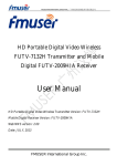
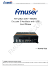
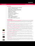
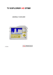
FMUSER INTERNATIONAL GROUP INC. 广州市汉婷生物技术开发有限公司
FUTV-8333 DVB-T Digital Transmitter
User’s Manual
FMUSER International Group Inc.
F
M
U
S
E
RI
N
T
E
R
N
A
T
I
O
N
A
LG
R
O
U
PI
N
C
.广州市汉婷生物技术开发有限公司
Alert & Disclaimer
Dear User,
Thanks for your choice of our FMUSER FUTV-8333 DVB-T Digital Transmitter.
Please read this manual carefully before you install and operate the devices. FMUSER shall have no
liability for any error or damage resulting from any breach or neglect of the manual.
Please properly keep this manual for the future reference.
About This Manual
Intended Audience
This user manual has been written to help people who have to use, to integrate and to install the
product. Some chapters require some prerequisite knowledge in electronics and especially in broadcast
technologies and standards.
Copy Warning
This document includes some confidential information. No part of this document may be reproduced
in any form without the written permission of the copyright owner. Its usage is limited to the owners
of the product that is relevant to. It cannot be copied, modified, or translated in another language
without prior written authorization from FMUSER.
1 / 44
F
M
U
S
E
RI
N
T
E
R
N
A
T
I
O
N
A
LG
R
O
U
PI
N
C
.广州市汉婷生物技术开发有限公司
2 / 44
F
M
U
S
E
RI
N
T
E
R
N
A
T
I
O
N
A
LG
R
O
U
PI
N
C
.广州市汉婷生物技术开发有限公司
DIRECTORY
Chapter 1 Introduction ......................................................................................................4
1.1 Outline .............................................................................................................................................. 4
1.2 Key Features .................................................................................................................................... 4
1.3 Technical Specifications.................................................................................................................. 5
1.4 System Principle .............................................................................................................................. 7
1.5 Constituent Devices and Function Description ............................................................................. 8
Chapter 2 Instruction of Installation and Operation..................................................21
2.1 Unpacking and Acquisition Check................................................................................................ 21
2.2 Installation Preparation ................................................................................................................. 21
2.3 Installation and Operation ............................................................................................................. 22
2.4 Digital RF Signal Debug ................................................................................................................ 31
2.5 Optical Signal Debug..................................................................................................................... 32
Chapter 3 Pre-Exciter Operation ...................................................................................35
3.1 Key Board Locking/Unlocking....................................................................................................... 35
3.2 LCD Operation ............................................................................................................................... 35
Chapter 4 Monitoring Unit Operation ...........................................................................38
Chapter 5 Operation of AMP Power .............................................................................43
Chapter 6 Services and Liability Assurance ..............................................................44
6.1 Maintains Services ........................................................................................................................ 44
6.2 Liability Assurance......................................................................................................................... 44
3 / 44
F
M
U
S
E
RI
N
T
E
R
N
A
T
I
O
N
A
LG
R
O
U
PI
N
C
.广州市汉婷生物技术开发有限公司
Chapter 1 Introduction
1.1 Outline
FUTV-8333 is a professional DVB-T digital transmitter newly developed by
FMUSER, which gives medium (600W) and sustained power output. Its compact
structure design has greatly saved space for your room. It supports SFN and MFN
network mode, output with both signal carrier mode and multi carrier mode, and
supports signal channel and broadband transmission.
The frequency range of FUTV-8333 is from 470MHz ~ 566MHz, 6060MHz ~
806MHz. This transmitter has a very high linear and high reliability as it takes high
gain and high linear LDMOS tube amplifier module. Furthermore, it supports AGC
function to keep sustained power output.
FUTV-8333 600W DVB-T digital transmitter can be widely used in HD/SD digital
TV signal transmitting and broadcasting system.
1.2 Key Features
Ø Enhanced signal transmission quality
Ø Intelligent and modularized amplifier unit, takes high power gain and high
linear LDMOS tube amplifier module design
Ø Low power consumption and super linear design to improve the transmission
power, and reduce the nonlinear distortion
Ø Support AGC function with sustained power output to allow the transmitter a
good stability and reliability
4 / 44
F
M
U
S
E
RI
N
T
E
R
N
A
T
I
O
N
A
LG
R
O
U
PI
N
C
.广州市汉婷生物技术开发有限公司
Ø Support MFN and SFN system
Ø Have the fault diagnosis function
Ø Full digital front panel control, easy operation.
Ø LED on the front panel support alarm and signal monitor
Ø Stabilized-power supply with wide range of voltage and high efficiency
Ø Amplifier and switching power supply one-for-one configuration, connect
directly to each other, reducing wired loss
Ø Cooling system with low consumption and low noise
Ø Multi lightning protection measures, good protection for whole equipment.
Ø 24-hour working unmanned, user friendly design
Ø Easy to install, elegant appearance
1.3 Technical Specifications
System
standard
Modulation
Mode
Frequency
Range
Basic
Parameters
output rating
DVB-T/DVB-C/MPEG-2
QAM4/16/32/64
470MHz~806MHz
600W
Output
characteristic
50Ω
impedance
variation of
output power
In-band stray
Out-of-band
suppression
Input
frequency
±0.25dB
≤-60dBc
≥65dBc
470MHz~806MHz
5 / 44
F
M
U
S
E
RI
N
T
E
R
N
A
T
I
O
N
A
LG
R
O
U
PI
N
C
.广州市汉婷生物技术开发有限公司
Input Level
-20 dBm±3dB
Input reflection
≥15dB
loss
Input Interface
‘N’
RF output
600W
power
Output
470MHz~806MHz
frequency
Output
50Ω
impedance
Output
frequency
±0.75dB
response
Shoulder level
≥36dB@central freqnencyIF±4.2MHz
output
≥20dB
reflection loss
Output
1-5/8 EIA
interface
Working
-20~+50℃
temperature
Storage
-30~+75℃
temperature
Relatively
Environment
condition
<95%(25℃ no condensation
humidity
Cooling mode
inside cooling fan
atm press
86~106kPa
power supply
AC,220V±10%/50Hz
Machine room
less dust,no shake
requirement
Working
-20~+50℃
temperature
Optical signal parameter
parameters
unit
Technical index
Optical wavelength
nm
1100-1600
6 / 44
F
M
U
S
E
RI
N
T
E
R
N
A
T
I
O
N
A
LG
R
O
U
PI
N
C
.广州市汉婷生物技术开发有限公司
norminal optical input
dBm
-1
Input optical power range
dBm
-7~+3
Max input optical power
dBm
+3
power
Optical interface
FC/APC
optical reflection loss
dB
≥45
output reflection loss
dB
≥12
inband flatness
dB
≤±0.5
1.4 System Principle
7 / 44
F
M
U
S
E
RI
N
T
E
R
N
A
T
I
O
N
A
LG
R
O
U
PI
N
C
.广州市汉婷生物技术开发有限公司
1.5 Constituent Devices and Function Description
The whole working system is composed of:
Modulator
RF IN
Pre-Exciter
Power
Distributor
Power
Amplifier 1
Power Supply 31
Power Supply 2
Power Supply 1
Power
Amplifier 2
ANT
Power
Combiner
Filter
RF OUT
Monitoring Unit
Items
Quantity
Power Supply
3 PCS
Modulator
1 PC
Pre-Exciter
1 PC
Power Distributor
1 PC
Power Amplifier
2 PCS
Power Combiner
1 PC
Filter
1 PC
Antenna
1 PC
Monitoring Unit
1 PC
8 / 44
F
M
U
S
E
RI
N
T
E
R
N
A
T
I
O
N
A
LG
R
O
U
PI
N
C
.广州市汉婷生物技术开发有限公司
Ventilation Casing
Rack
Power Amplifier 2
Power Amplifier 1
Monitoring Unit
Pre-Exciter
Modulator
Power Switch
Power Supply 1-3 for the 2 Power Amplifiers
Face Side
9 / 44
F
M
U
S
E
RI
N
T
E
R
N
A
T
I
O
N
A
LG
R
O
U
PI
N
C
.广州市汉婷生物技术开发有限公司
Filter
Rack
Power Combiner
Power Amplifier 1
Power Amplifier 2
Power Distributor
Monitoring Unit
Pre-Exciter
Modulator
Power Supply 1-3 for the 2 Power Amplifiers
Back Side
Back Side of the Constituent Device
10 / 44
F
M
U
S
E
RI
N
T
E
R
N
A
T
I
O
N
A
LG
R
O
U
PI
N
C
.广州市汉婷生物技术开发有限公司
1.5.1 Pre-Exciter front panel
1
23 4
Serial No.
5
6
7
Item
1
LCD Window
2
Indicators of signal strength output from the exciter
3
Button of LCD-page turning
4
Buttons of adjusting the strength of input signals
Control button & indicators of the power supply of
5
6
7
the final amplifier
Control button & indicators of working mode
(AGC/MGC)
button to lock the key board & indicators
11 / 44
F
M
U
S
E
RI
N
T
E
R
N
A
T
I
O
N
A
LG
R
O
U
PI
N
C
.广州市汉婷生物技术开发有限公司
1.5.2 Pre-Exciter back panel
2
1
3
6
4
Serial No.
7
Item
1
RF Input port
2
Optical Input
3
RF Output port
4
Cooling fans
Fuse/power
5
5
supply
socket/
switch for the pre-exciter
6
Monitoring port
7
power supply/fuse for the fans
12 / 44
F
M
U
S
E
RI
N
T
E
R
N
A
T
I
O
N
A
LG
R
O
U
PI
N
C
.广州市汉婷生物技术开发有限公司
1.5.3 Power Amplifier front panel
1
2
3
4
Serial No.
Item
1
Power indicator
2
Amplifier working status (normal) indicator
3
Amplifier alarm indicator
4
Handle
13 / 44
F
M
U
S
E
RI
N
T
E
R
N
A
T
I
O
N
A
LG
R
O
U
PI
N
C
.广州市汉婷生物技术开发有限公司
1.5.4 Power Amplifier back panel
1
2
3
4
5
6
7
Serial No.
Item
1
RF Output port
2
RF Test Port
3
RF Input port
4
DC Power Input Socket
5
Monitoring Port
6
Reflect-power Detection Pin
7
Output-power Detection Pin
14 / 44
F
M
U
S
E
RI
N
T
E
R
N
A
T
I
O
N
A
LG
R
O
U
PI
N
C
.广州市汉婷生物技术开发有限公司
1.5.5 Filter
1
2
Serial No.
Item
1
RF Input Port (connect to power combiner)
2
RF Output Port (connect to antenna)
15 / 44
F
M
U
S
E
RI
N
T
E
R
N
A
T
I
O
N
A
LG
R
O
U
PI
N
C
.广州市汉婷生物技术开发有限公司
1.5.6 Monitor Unit Front Panel
T
o
u
c
hM
o
n
i
t
o
rS
c
r
e
e
n
16 / 44
F
M
U
S
E
RI
N
T
E
R
N
A
T
I
O
N
A
LG
R
O
U
PI
N
C
.广州市汉婷生物技术开发有限公司
1.5.7 Monitor Unit Back Panel
1
2
3
Serial No.
1
6
4 5
7
8 9
Item
Power switch/fuse/socket
Amplifier Power Supply interface (to protect the
2
power supply if the output power overload)
3
Ethernet Ports
4
Reset Button
5&6
7
8
9
Power Monitoring input port
Amplifiers 1&2 Monitoring input port
Power Combiner Monitoring input port (to monitor
the whole unit)
Per-Exciter Monitoring input port
Remarks: the rest interfaces are not put in use so far.
17 / 44
F
M
U
S
E
RI
N
T
E
R
N
A
T
I
O
N
A
LG
R
O
U
PI
N
C
.广州市汉婷生物技术开发有限公司
1.5.8 Power Supply (for power amplifiers) Front Panel
18 / 44
F
M
U
S
E
RI
N
T
E
R
N
A
T
I
O
N
A
LG
R
O
U
PI
N
C
.广州市汉婷生物技术开发有限公司
1.5.9 2-in-1 Power Combiner
1
3
4
5
6
2
Serial No.
Item
1
RF Output port
2
RF Input ports 1 & 2
3
Monitoring Port
4
Whole reflection power test pin
5
Whole power output test pin
6
Whole RF output monitoring port
19 / 44
F
M
U
S
E
RI
N
T
E
R
N
A
T
I
O
N
A
LG
R
O
U
PI
N
C
.广州市汉婷生物技术开发有限公司
1.5.10 Power Distributor
1
2
Serial No.
Item
1
RF output port 1 & 2
2
RF Input port
20 / 44
F
M
U
S
E
RI
N
T
E
R
N
A
T
I
O
N
A
LG
R
O
U
PI
N
C
.广州市汉婷生物技术开发有限公司
Chapter 2 Instruction of Installation and
Operation
2.1 Unpacking and Acquisition Check
After a strict debugging, burn-in and testing, every constituent device (modulator,
pre-exciter, power supply…) of this transmitter is packed separately in wooden
boxes to facilitate the long-way transit.
Please unpack the boxes carefully and check the items according to the packing
list attached. If any item missing, please contact the supplier immediately.
2.2 Installation Preparation
When users install device, please follow the below steps. The details of
installation will be described at the rest part of this chapter.
l
Check the possible device missing or damage during the transportation
l
Prepare a relevant environment for installation
l
Stand the rack
l
Fix the positioning bolt to avoid slide or topple
l
Read the user manual
Read this manual carefully and follow the steps stated. Operators are required to have some
prerequisite knowledge in electronics and especially in broadcast technologies and standards.
21 / 44
F
M
U
S
E
RI
N
T
E
R
N
A
T
I
O
N
A
LG
R
O
U
PI
N
C
.广州市汉婷生物技术开发有限公司
2.2.1 Power Supply
The input voltage is required to be 220VAC, 50/60Hz. To ensure the safety of the device and
operators, this transmitter adopts three-wire plug with one of the wires to connect to the
ground. The specification of the ground wire shall comply with the local standard and
regulation.
Voltage in the socket shall not overload. Cares should be taken when you use extending
power-line or integrated plug seat in case possible risk of electric shock or fire.
2.2.2 Working Environments
The transmitter should been placed in a ventilated and dry place for working to avoid
overheat, wet and dust. It is also required to keep far away from heart source to make sure
the equipment can work well.
2.2.3 Lightning protection
To avoid the damage caused from thunder or mains fluctuation, please make sure to use
transmitter in the place where have lightning arrester.
2.2.4 Ground connection
The ground connection side of this device should connect to copper bar of protected area.
Make the ground wire as short as possible. If the ground wire is too long, just cut short to
avoid the ground wire wind round together. The cross area of ground wire must ≥25 mm 2 ,
and ground resistance must ≤ 4Ω.
2.3 Installation and Operation
Please install and operate step by step as following:
2.3.1 Stand the rack and fix the positioning bolt to avoid slide or topple
2.3.2 Install the each constituent device on the rack
22 / 44
F
M
U
S
E
RI
N
T
E
R
N
A
T
I
O
N
A
LG
R
O
U
PI
N
C
.广州市汉婷生物技术开发有限公司
Push the 3 Power suppliers in the slots and fix them by screwing the two ends.
Push the Pre-Exciter in this slot and fix it by screwing the four corners.
Push the Monitoring Unit in this slot and fix it by screwing the four corners.
23 / 44
F
M
U
S
E
RI
N
T
E
R
N
A
T
I
O
N
A
LG
R
O
U
PI
N
C
.广州市汉婷生物技术开发有限公司
Push the 2 power amplifiers in the slots and fix them by screwing the two ends
4
*
Place the filter on the top of the rack and fix it by screwing the four feet.
2.3.3 Connect the power wires & signal cables & monitoring cables
Modulator
RF IN
Pre-Exciter
Power
Distributor
Power
Amplifier 1
Power Supply 31
Power Supply 2
Power Supply 1
Power
Amplifier 2
ANT
Power
Combiner
Filter
RF OUT
Monitoring Unit
24 / 44
F
M
U
S
E
RI
N
T
E
R
N
A
T
I
O
N
A
LG
R
O
U
PI
N
C
.广州市汉婷生物技术开发有限公司
l
Install the transmit antenna on to the transmit tower. (Antenna is extra
equipment which we do not offer unless the customer requires to purchase.)
l
Connect RF output interface of the filter to the input interface of antenna with a
soft feeder.
The RF output interface in open circuit (disconnect antenna) may
bring damage to transmitter
l
Connect RF output interface of the combiner to the input interface of filter with
a hard feeder
25 / 44
F
M
U
S
E
RI
N
T
E
R
N
A
T
I
O
N
A
LG
R
O
U
PI
N
C
.广州市汉婷生物技术开发有限公司
B
A
A
B
A
M
P1
l
A
M
P2
Connect RF output interface of the amplifiers to the input interface of combiner
with feeders (AMP 1 & AMP 2 shown above).
The two feeders are different and exclusive for each
amplifier (AMP 1 to connect port A; AMP 2 to connect port B).
Read the labels stuck onto the feeders and connect to the
corresponding ports. No exchange is allowed
l
Connect the monitoring port on the combiner to the Monitoring Unit.
26 / 44
F
M
U
S
E
RI
N
T
E
R
N
A
T
I
O
N
A
LG
R
O
U
PI
N
C
.广州市汉婷生物技术开发有限公司
A
B
A
M
P1
A
M
P2
A
l
B
Connect RF output interface of the distributor to the input interface of
amplifiers with cables (AMP 1 & AMP 2 shown above)
The two cables are different and exclusive for each
amplifier (AMP 1 to connect port A; AMP 2 to connect port B).
Read the labels stuck onto the cables and connect to the
corresponding ports. No exchange is allowed
l
Connect the monitoring ports (signal detection ports) on the amplifiers to the
Monitoring Unit. One end of the monitoring cable connect to amplifier 1 (2) and
the other end to “AMPLIFIER 1” (“AMPLIFIER 2”) port on the Monitoring Unit.
(shown as picture below)
27 / 44
F
M
U
S
E
RI
N
T
E
R
N
A
T
I
O
N
A
LG
R
O
U
PI
N
C
.广州市汉婷生物技术开发有限公司
l
Connect RF output interface of the pre-exciter to the input interface of
distributor with cable. (shown above)
l
Connect RF output interface of the modulator (or other signal source device
from the users) to the input interface of pre-exciter with cable. (shown above,
the left cable)
l
Connect the monitoring port on the pre-exciter to the Monitoring Unit.
28 / 44
F
M
U
S
E
RI
N
T
E
R
N
A
T
I
O
N
A
LG
R
O
U
PI
N
C
.广州市汉婷生物技术开发有限公司
l
An overview of the cable connection of the Monitoring Unit
(the 2 pictures below)
This cable connects the monitoring unit and the AMP
power to protect the AMP power suppliers. The AMP power will
be cut off automatically to protect itself from burn-out if any of
following errors happens.
A)
The
working
temperature
of
any
of
the
two
power
amplifiers
exceeds 65 ℃.
B)
Output power overload: The whole output power exceeds 25% of the
rated power. (>750W)
C)
The whole reflect power reaches 25% of the rated power. (150W)
29 / 44
F
M
U
S
E
RI
N
T
E
R
N
A
T
I
O
N
A
LG
R
O
U
PI
N
C
.广州市汉婷生物技术开发有限公司
This monitoring interface (POWER MONITOR) is to monitor the power suppliers. It
is connected to the power suppliers and offers information (Voltage) on the touch
screen in the front panel.
2.3.4 Connect the ground pole (at the bottom of the rack) with earth lead.
2.3.5 Make sure the power switch is in OFF state and connect the power joint
(at the bottom of the rack) of the transmitter to the room’s power
supply with the three-core line as shown in below picture. This is to
offer power to the pre-exciter, ventilation casing, and monitoring unit.
Note: voltage must be AC 220V 50Hz and no cross of “L” pole and
“N” pole. (“L”: Live Wire; “N”: Neutral Wire)
30 / 44
F
M
U
S
E
RI
N
T
E
R
N
A
T
I
O
N
A
LG
R
O
U
PI
N
C
.广州市汉婷生物技术开发有限公司
2.3.6 Turn on the power. After a second the transmitter starts to work
2.4 Digital RF Signal Debug
If the input signal is digital RF, users can debug and set the signal through
pre-exciter as follows:
1. Connect the RF output port to antenna;
2. Connect the RF IN port to the signal source cable;
3. Turn on the main power switch; (The 3 steps have been completed in 2.3.)
4. Check whether the working state is normal from the pre-exciter ’s LCD window;
5. Set the working mode as MGC through the key board (MGC indicator lights up.)
6. Debug the output power according to power indicators.
Output
Indicator
power
Alarm
Solutions
Press SELECT key to
turn LED to page “RF
Yellow
too low
yes
IN ATT” and press UP
button to increase the
ATT (attenuation).
Green
Normal
no
N/A
Red
too
yes
Press SELECT key to
31 / 44
F
M
U
S
E
RI
N
T
E
R
N
A
T
I
O
N
A
LG
R
O
U
PI
N
C
.广州市汉婷生物技术开发有限公司
high
turn LED to page “RF
IN ATT”
and
DOWN
button
decrease
the
press
to
ATT
(attenuation).
NOTE:
l
The key board can only be operated until it is unlocked by pressing the LOCK
button.
l
ATT value increases, while signal strength decreases.
l
ATT value decreases, while signal strength increases
l
Refer to 3.3 for more detailed operations
7. When the power indicator turns to green, which signifies the output power is
normal, set the working mode as AGC through the key board. 40-60 seconds
later, the transmitter starts working automatically.
2.5 Optical Signal Debug
If the input signal is optical, users can debug and set the signal through
pre-exciter as follows:
1. Connect the RF output port to antenna;
2. Connect the Optical IN port to the signal source cable;
3. Turn on the main power switch; (The 3 steps have been completed in 2.3.)
4. Check whether the working state is normal from the pre-exciter ’s LCD
window
5. Set the working mode as MGC through the key board
32 / 44
F
M
U
S
E
RI
N
T
E
R
N
A
T
I
O
N
A
LG
R
O
U
PI
N
C
.广州市汉婷生物技术开发有限公司
6. Debug the output power according to power indicators.
Output
Indicator
power
Alarm
Solutions
Press SELECT key
to turn LED to page
“RF
Yellow
too low
yes
IN
ATT”
and
press UP button to
increase
the
ATT
(attenuation)
Green
Normal
no
N/A
Press SELECT key
to turn LED to page
too
Red
high
“RF
yes
IN
ATT”
and
press UP button to
decrease
the
ATT
(attenuation)
NOTE:
l
The key board can only be operated until it is unlocked by pressing the LOCK
button.
l
ATT value increases, while signal strength decreases.
l
ATT value decreases, while signal strength increases
l
Refer to 3.3 for more detailed operations
7. When the power indicator turns to green, which signifies the output power is
33 / 44
F
M
U
S
E
RI
N
T
E
R
N
A
T
I
O
N
A
LG
R
O
U
PI
N
C
.广州市汉婷生物技术开发有限公司
normal, set the working mode as AGC through the key board. 40-60 seconds
later, the transmitter starts working automatically
REMARKS: Please advise the whether your signal source is digital RF or
optical signal when you place an order.
Warnings:
1. Open circuit output port is not allowed;
2. No inserting or drawing cables when the transmitter is working;
3. The transmitter is equipped with high-voltage components. Don’t remove
the cover unless the security is ensured;
4. Please contact the authorized maintenance man if any breakdown occurs.
34 / 44
F
M
U
S
E
RI
N
T
E
R
N
A
T
I
O
N
A
LG
R
O
U
PI
N
C
.广州市汉婷生物技术开发有限公司
Chapter 3 Pre-Exciter Operation
3.1 Key Board Locking/Unlocking
Press LOCK key for 3 seconds to unlock the key board (the locking indicator goes
out) to operate the pre-exciter. After finishing operation, please press LOCK key
for 3 seconds to lock the key board (the locking indicator lights up) to avoid
mis-operation.
3.2 LCD Operation
3.3.1 Interfaces of input-signal strength
RF IN ATT:0dB
RF IN ATT:15dB
RF IN ATT:31dB
Above interfaces display the information about adjusting the input signal strength.
35 / 44
F
M
U
S
E
RI
N
T
E
R
N
A
T
I
O
N
A
LG
R
O
U
PI
N
C
.广州市汉婷生物技术开发有限公司
When you start debug the signal power, follow the steps as below:
l
Set the working mode as “MGC”
l
Turn the LED to page “RF IN ATT” by pressing SLECT.
l
Press “▲”or “▼” to modify the value (0~ 31dB) until it indicates the output
power is normal (the green indicator lights up)
l
Set the working mode as “AGC”
3.3.2 Temperature
Temperate:25℃
It displays the current environment temperature. Press SELECT to turn the LED to
this page. It is the read-only and can’t be modified.
3.3.3 PA (Power Amplifier) Power
DC(PA Power)
:
Read: 48.0V
It displays the current power voltage of the power amplifiers. Press SELECT to
turn the LED to this page. It is the read-only and can’t be modified.
3.3.4 Input Optical Signal Power
Input Optical Power
Read:Low
36 / 44
F
M
U
S
E
RI
N
T
E
R
N
A
T
I
O
N
A
LG
R
O
U
PI
N
C
.广州市汉婷生物技术开发有限公司
Input Optical Power
Read:-1dBm
Input Optical Power
Read:High
Above interfaces display the information of the input optical signal strength. It is
read-only. When it displays LOW, it indicates the optical power is under -7dBm.
Likely, -1dBm indicates the actual optical power (-7dBm~ +3dBm), and HIGH
indicates the optical power is over +3dBm.
REMARKS: -1dBm is the recommended optical power.
3.3.5 Software Version
Software Version
Version:0.5
It displays the software version number of this device. Press SELECT to turn the
LED to this page. It is the read-only and can’t be modified.
37 / 44
F
M
U
S
E
RI
N
T
E
R
N
A
T
I
O
N
A
LG
R
O
U
PI
N
C
.广州市汉婷生物技术开发有限公司
Chapter 4 Monitoring Unit Operation
Monitoring unit can real-timely put a watch on electric current, voltage, power and
etc and show these numbers on the touch screen. Users can enter the
sub-interface to check the specified parameters (the parameters cannot be
configured through this monitoring unit.).
Below picture shows the main monitoring overview of each constituent device
(Pre-Exciter, containing exciter and Pre-Amplifier, Power splitter, 2 final amplifiers,
filter, AMP power and antenna.) and the basic signal flow.
If an error happens on any constituent device of the transmitter, it will give alarm
and its corresponding icon turns red to indicate errors.
38 / 44
F
M
U
S
E
RI
N
T
E
R
N
A
T
I
O
N
A
LG
R
O
U
PI
N
C
.广州市汉婷生物技术开发有限公司
NOTE: Only Pre-Amplifier, AMP 1, AMP 2, ANT (antenna), or AMP Power will give
alarm if any error happens on any one of them.
Alarm Interface
Touch the error device icon, and it goes to the sub-interface to display detailed
parameters and show where problems lie.
39 / 44
F
M
U
S
E
RI
N
T
E
R
N
A
T
I
O
N
A
LG
R
O
U
PI
N
C
.广州市汉婷生物技术开发有限公司
or
40 / 44
F
M
U
S
E
RI
N
T
E
R
N
A
T
I
O
N
A
LG
R
O
U
PI
N
C
.广州市汉婷生物技术开发有限公司
Introduction of Other Functions of Monitoring Unit
To reset the transmitter: For example, when the AMP power is cut off due to
the amplifier ’s overload output power / over-high temperature / over-high reflect
power. Press this button to reboot the AMP power after cleaning the trouble.
Touch this button to turn off the buzzer when the device gives alarm
To set the system: press this button and it goes to interface as below:
41 / 44
F
M
U
S
E
RI
N
T
E
R
N
A
T
I
O
N
A
LG
R
O
U
PI
N
C
.广州市汉婷生物技术开发有限公司
Touch the item you are to modify and it pops out a soft key board for inputting new
data. Press
to finish the setting and
to save the settings.
42 / 44
F
M
U
S
E
RI
N
T
E
R
N
A
T
I
O
N
A
LG
R
O
U
PI
N
C
.广州市汉婷生物技术开发有限公司
Chapter 5 Operation of AMP Power
There are 3 AMP Powers located at the bottom of the rack. They are used to offer power for
the amplifier 1 & 2.
It is equipped with a LED screen on each power to display its current and voltage.
Alarm indicator
Press I/V button to shift the display of current and voltage on the LED screen.
Current
Voltage
43 / 44
F
M
U
S
E
RI
N
T
E
R
N
A
T
I
O
N
A
LG
R
O
U
PI
N
C
.广州市汉婷生物技术开发有限公司
Chapter 6 Services and Liability Assurance
6.1 Maintains Services
6.1.1 Contact our authorized maintains man or the local agent if you need
technical services.
6.1.2 If you cannot contact our agent or distributor, please contact the
headquarters in China and return the device if needed.
6.1.3 If you return any device for maintains, please attach an appendix to illustrate
the breakdowns and necessary accessories. Please also provide the sender,
contact number, address and etc to us.
6.2 Liability Assurance
6.2.1 We will charge if the device is not under warranty or the damage is caused
by your improper operation.
6.2.2 Our company offers a one-year warranty to our direct customers. We will
offer free maintains within 12 months counting from the delivery date due to the
production problem or material factor.
6.2.3 The liabilities assured is limited our company or the designated agent, and
we are in the position to test and identify the damage or fault is whether original or
not.
6.2.4 If the terminal users modify the internal technical design (software upgrade)
without permission, we will have no liability for any damage or fault caused there
from even the device is still under warranty.
44 / 44