1
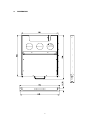
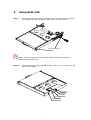
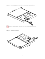
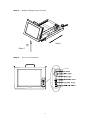
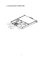
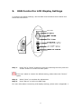
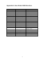
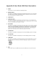
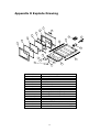
RLM-150
LCD Monitor Drawer
User Manual
Version 1.0
November 10, 2003
Copyright Notice
©Copyright 2003 by ICP Electronics Inc. All Rights Reserved.
The information in this document is subjected to change without prior notice in
order to improve reliability, design and function and does not represent a
commitment on the part of the manufacturer.
In no event will the manufacturer be liable for direct, indirect, special, incidental,
or consequential damages arising out of the use or inability to use the product or
documentation, even if advised of the possibility of such damages.
This document contains proprietary information protected by copyright. All rights
are reserved. No part of this manual may be reproduced by any mechanical,
electronic, or other means in any form without prior written permission of the
manufacturer.
Trademarks
RLM-150 is a registered trademark of ICP Electronics Inc. IBM PC is a registered
trademark of International Business Machines Corporation. Intel is a registered
trademark of Intel Corporation. Other product names mentioned herein are used
for identification purposes only and may be trademarks and/or registered
trademarks of their respective companies. If you have any questions or need
other information, please visit to our web site.
http://www.ieiworld.com
2
Table of Contents
1.
INTRODUCTION..............................................................................4
1.1
1.2
FEATURES ......................................................................................4
CHECKLIST .....................................................................................4
2.
SPECIFICATIONS ...........................................................................5
3.
USING RLM-150 .............................................................................7
4.
OVERALL VIEW OF RLM-150.........................................................10
5.
OSD CONTROL FOR LCD DISPLAY SETTINGS ................................11
APPENDIX A
USER MODE OSD STRUCTURE ..............................12
APPENDIX B
USER MODE OSD ITEM DESCRIPTION ..................13
APPENDIX C
POWER ADAPTER SPECIFICATION .......................14
APPENDIX D
EXPLODE DRAW...................................................15
3
1.
Introduction
The RLM series consists of a 15” LCD screen. This all-in-one design is the best
choice for easy set-up and user-friendly operation in the industrial environment.
1.1 Features
Could be connected directly to a computer.
Equipped with a 15” high brightness TFT LCD screen using a panel interface
with 15 pins D-type connector, which conforms to the VGA standard.
Slim body design with 1U height, saving rack space.
1.2 Checklist
Item
Description
Qty.
1
RLM-150 User Manual
1
2
Power Cable
1
3
RACK Mounting kit
2
4
Screw Accessories
1
5
RLM-150 rack mount drawer 15” LCD monitor
1
4
2.
Specifications
LCD Display:
TTL LCD connector interface supports the screen reverse
function.
Display Model: CHI MEI
Display Type: 15” TFT color
LCD Model: M150X2-T05
Resolution: 1024 x 768
Display Colors: 262,144 color
Brightness: 250 cd/m2
Viewing Analog: 160(H) x 160(V)
LCD MTBF: 50,000 hrs
Backlight MTBF: 30,000 hrs
Supply Voltage: 3.3V
Standard Power Adapter: +12 VDC/3.75A
Standard D-sub 15Pin VGA Input connector
Vibration:
5~17Hz, 0.1”double amplitude displacement
17~640Hz, 1.5G acceleration peak to peak
Shock: 10G acceleration peak to peak (11ms)
Storage Temperature:
-20~60ºC
Operation Temperature:
0~50ºC
Color: Black (PANTONE BLACK C), White (PANTONE 433C)
Depth: 510mm
Optional Touch Screen:
3M Resistive Touch Screen
Type: Analog Resistive
Resolution: Continuous
Light transmission: Typical value 75%
Surface Hardness: 4H (Test condition: ASTM D3363-92A)
8-wire touch screen
Touch screen interface: RS-232
Support driver:
Supports Linux, MS-DOS, Windows 3.1/95/ 98/CE,
ME/2000/NT,OS/2,MAC,etc.
5
DIMENSION
6
3.
Using RLM-150
Step 1.
Unwrap the package and mount RLM-150 on the rack provided. RLM150 supplies the rear bolster to make rack mounting easier.
For Rack mount
Please switch the power off and unplug adapter before connecting or
disconnecting to RLM-150
Step 2.
Connect RLM-150 (using standard VGA), cable to the computer as the
figure shown below.
PS/2 Port
USB Port
RS-232 Port
VGA Port
POWER INPUT
7
Step 3.
Plug the adapter into RLM-150 as shown in the following figure.
Please be aware of static electricity when you establish each connection.
Step 4.
OPEN Monitor Drawer.
8
Step 5.
Multiple sliding Monitor function.
Step 1
UP
Step 2
Step 6.
Turn on the computer.
LEFT Button
RETURN
/ MENU
ON/OFF
POWER
9
4. Overall View of RLM-150
POWER INPUT
VGA PORT
RS-232 PORT
USB PORT
P/S2 PORT
10
5.
OSD Control for LCD Display Settings
To change LCD display settings, use the OSD control buttons shown below and
follow the instructions.
LEFT Button
RETURN
/ MENU
ON/OFF
POWER
Step 1.
Using “Up” & “Down” buttons to move the selecting bar then press the
“Select” button to choose the OSD option.
If the user wants to restore the default setting, please select the “Revert”
option.
Step 2.
Step 3.
Select “Save” to complete the adjustment.
Press “Return” to leave the OSD page.
For more information concerning LCD display settings, please refer to Appendix 1.
11
Appendix A User Mode OSD Structure
LEVEL 0
DISPLAY ADJUST
INPUT SELECT
COLOR ADJUST
OSD ADJUST
ZURAC ADJUST
EXIT
LEVEL 1
H-Position
V-Position
CLOCK
PHASE
AUTO
EXIT
ANALOG
DIGITAL
VIDEO COMPOSITE
VIDEO S-VIDEO
EXIT
COLOR TEMPERATURE
RED GAIN
GREEN GAIN
BLUE GAIN
EXIT
H-Position
V-Position
OSD-OFF TIME
LANGUAGE
EXIT
BRIGHTNESS-Z
CONTRAST-Z
DOS-MODE
CONTRAST-ADC
EXIT
EXIT OSD
12
VALUE
0-255
0-30
0-1788
0-31
YES , NO
Press Menu Button
Press Menu Button
Press Menu Button
Press Menu Button
Press Menu Button
Press Menu Button
6500K , 9300K
0-255
0-255
0-255
Press Menu Button
0-255
0-255
0-120
English , Espanol , Deutsch ,
Frangais ,Italiao
Press Menu Button
0-255
0-255
TEXT , GRAPHICS
0-255
Press Menu Button
Press Menu Button
Appendix B User Mode OSD Item Description
PHASE
This function is used to adjust the sampling Phase.
BRIGHTNESS-Z
This option is available for adjusting the brightness of screen. You can adjust
the offset value of ZURAC through this option. Setting this value too high or
too low will destroy the quality of image.
CONTRAST-Z
CONTRAST-ADC
This option is available for adjusting contrast of screen. You can adjust the
gain value of ZURAC or ADC through this option. Adjusting this value too high
or too low will destroy the quality of image.
DOS-MODE
This option is available for selecting VGA input signal, to text mode or graphic
mode. (It is only selectable on resolution of 720/640x400 or 720/640x350.)
400 and 350 standard IBM modes have the same H-sync. and V-sync. value
so AV-0911 MPU cannot differentiate them automatically. You will need to
adjust them manually so as to match the proper VGA mode.
H-POSITION
This option is available for adjusting the horizontal display position of image.
V-POSITION
This option is available for adjusting the vertical display position of image.
LANGUAGE
This option is available for selecting language used on OSD display. AV-0911
now can support the following 5 different languages. English is the default
language.
English
Espanol
Deutsch
Frangais
Italiao
Exit
Press ‘EXIT’ key to exit OSD menu when the OSD menu is at the first level.
13
Appendix C Power Adapter Specification
Model no: UP0451E-12P67L
Input requirements:
Input Voltage range: 90 to 264 VAC.
Line frequency: 47 to 63 HZ.
In-Rush current: 40A max
Output:
Output Voltage range at +12V ±0.5V 3.75A 45 Watt
Ripple and Noise: Voltage 120 mV
Operating environmental conditions:
Ambient Temperature: 0°C~40°C.
Relative Humidity: 5%~95%.
Altitude: Sea level to 10,000 feet.
Vibration: 10-55Hz, 15 minutes X,Y,Z Axis cycle:20.
Efficiency: 80%
EMI emissions:
The power supply meets the radiated and conducted emission
requirements for a (CISPR22 CLASS B) and a (FCC CLASS B).
MTBF:
When the power supply is operated within the limits of the abovementioned specifications, the MTBF shall be at least (150,000) hours
at 25°C.
14
Appendix D Explode Drawing
7
6
8
5
4
20
3
2
19
21
16
1
18
12
11
17
10
9
14
13
Part No.
1
2
3
4
5
6
7
8
9
10
11~15
16~17
18
19
20
21
15
Component
External Panel
Front Frame
Tempered Glass
LCD
LCD Steady
Rear Rack
Rear Cover
Handle
Bearing Slide Lock (front)
Bearing Slide Lock (rear)
Corner Braces
Slide
Power Supply
Power Cable
Stationary Barrier for Power Supply
Stand
15