1
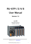
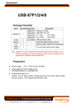
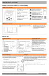
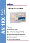
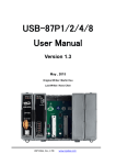
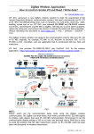
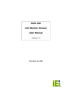
RACK-250 CHASSIS
USER’S MANUAL
Copyright Notice
This document and product is copyrighted, Jun 1999, by ICP Electronics Inc. All
rights are reserved. No part of this manual may be reproduced, copied, or
translated without prior notice to ICP Electronics Inc.
The information provided in this document is for reference only. We do not assume
any responsibility arising out of the application of the products. This manual is
subject to change without any notice.
RACK-250 and ICP are trademark of ICP Electronics Inc.
1
Table of Contents
Chapter 1
Product Information
1.1 General Information
1.2 Product Specifications
1.3 Dimensions
Chapter 2
System Setup
2.1 Front Panel of RACK-250
2.2 LP-01 Control Panel of RACK-250
2.3 Rear Panel of RACK-250
2.4 Removing the chassis cover
2.5 Multimedia POS Control Board Installation
2.6 Disk Drives Installation
2.7 Replacing the Filter
2.8 Power Supply Installation
2.9 Fan Installation
2.10 Power and Control Board Cable Connecting
Appendix A
Passive Control Board
Appendix B
Exploded Diagram
2
Chapter 1 Product Information
1.1 General Information
RACK-250 IPC chassis is a rugged PC/AT compatible computer designed for the
factory floor and other Industrial harsh environment. RACK-250 is designed for
POS-566 POS Control Board and standard equipped with ACE-890 series power
supply.
1.2 Product Specifications
General specification
- Construction
- Disk Driver
- Cooling Fan
- Indicator
- Dimension
:
:
:
:
:
Heavy-duty steel
One 3.5” FDD and One 3.5” HDD drive space
Dual Ball bearing fans
Two LEDs to monitor the status of HDD and Power Supply
484 x 412 x 44 ( W x D x H )
Power Supply
Standard equipped power supply for the RACK-250 is : ACE-890A. / 90W
Optional: ACE-890P 70V -132VDC input power supply.
ACE-890T 36V -72VDC input power supply.
ACE-890C 18V -36VDC input power supply.
ACE-890V 9V -16VDC input power supply.
3
Working Environment
- Operating Temperature
- Relative Humidity
- Vibration
:
:
:
- Shock
- Safety approval
:
:
0~50°C
5~95% Relative humidity
5-17Hz, 0.1” doubl e amplitude displacement
17-640Hz, 1.5G acceleration peak to peak
10G acceleration peak to peak
meet CE, FCC
Cooling Fan
Dual rear ball bearing cooling fans for optimum system cooling.
Drive Capacity
One 3.5” FDD and one 3.5” HDD drive space
4
1.3 Dimensions
412.0
484mm x 44mm x 412mm ( W x H x D )
32.0
6.0
44.0
4-O6.5x10(OB)
431.0
466.0
484.0
5
UNIT:mm
Chapter 2 Installation Procedure
The following procedure is provided to assist you in installing the system, please
follow the steps below:
2.1 Front Panel of RACK-250
The front panel is equipped with Power Switch, Reset Switch, Power LED and
HDD LED as the following diagram shown.
RESET SWITCH
POWER LED
POWER SWITCH
6
HDD LED
2.2 LP-01 Control Panel of RACK-250
Rack-250 is equipped with LP-01 control board. Please refer to the following
figure as you set up your system.
RESET SWITCH
BUZZER
POWER LED(GREEN)
HDD LED(RED)
1 2 3 4 5 6 7 8 Pin
NOTE: 1,2 PIN-BUZZER
3,4 PIN-POWER LED(GREEN)
5,6 PIN-HDD LED(RED)
7,8 PIN-RESET SWITCH
LP-01 Panel
BZ1: BUZZER
D1:POWER LED
D2: System HDD LED
SW1: RST system reset button
CN1:
1
8
7
Pin #
FUNCTION
1
2
3
SPEAKER (+)
SPEAKER (-)
POWER LED (-)
4
5
6
7
POWER LED (+)
HDD LED(-)
HDD LED(-)
RESET (1)
8
RESET (2)
2.3 Rear Panel of RACK-250
Please refer to the following diagram which illustrates the equipment of the
rear panel .
AC INPUT
VGA Port
Printer Port
LINE OUT
COM1/COM2
LINE IN
MIC
NETWORK LED
8
MOUSE
PORT
EXT. K/B
10/100 Base-T
Ethernet
2-USB Port
2.4 Removing the chassis cover
The cover is mounted by some screws on the top of the chassis. Hence,
you can remove the screws and open the cover of chassis directly. Figure
below shows how to remove the chassis cover.
9
2.5 Multimedia POS Control Board Installation
Figure below illustrates how to install the POS Control Board on the
RACK-250 .
2.6 Disk Drives Installation
10
1. Open the upper disk drive cover.
2. Fix the HDD and FDD into bracket and then install them into the
chassis.
3. Connect the necessary cables.
Step 1
Step 2
Step 2
Step 1
11
2.7 Replacing the Filter
The filter of the RACK-250 is located at the front end of the chassis. Just
replace it with the new one if it’s already worn out. The filter should be
removed and cleaned at least once a month to achieve optimum performance.
12
2.8 Power Supply Installation
Please refer to the figure below to install the Power Supply.
13
Model
Input Voltage
ACE-890A
85V to 264VAC
Rated Load
+5V +12V -12V
10A
2.5A 0.5A
Max Output
+5V +12V -12V
12A
4A
1A
2.9 Fan Installation
The following diagram is provided for your reference as you install the Fan and
connect to the Power Supply.
ACE-890A
POWER
SUPPLY
14
2.10 Power and Control Board Cable Connecting
Please refer to the following diagrams to connect the cables to the Control
Board.
POS-566
Control Board
ACE-890A
POWER
SUPPLY
POS-566
Control Board
RES
ET S
PO
ZER
WITC
LE
WER
H
D(GR
EEN
BUZ
HDD
LED
(RED
)
IP-52
15
)
219.99
PASSIVE CONTROL BOARD
190.02
0.00
10.01
APPENDIX A
0.00
42.01
DiskOnChip
182.02
235.00
UNIT:mm
16
APPENDIX B
17
EXPLODED DIAGRAM