1
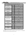
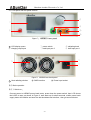
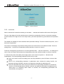
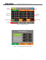
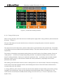
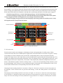
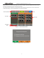
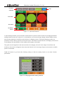
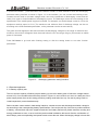
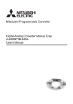
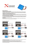
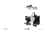
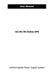
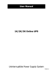
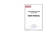
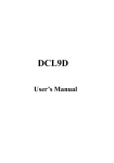
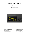
ASunDar Users Manual ASD905 Power Bank Tester VR:0.9 Shenzhen Asundar Electronics Co., Ltd www.asundar.com Shenzhen Asundar Electronics Co, Ltd Foreword Thank you for purchasing the product of Shenzhen Asundar Electronics Co.,Ltd! This manual describes how to use ASD905 mobile power supply tester (referred to as the product in this manual). Before use, please read this user manual carefully. Attentions When open the package, make carefully inspection and confirm that ① product model is consistent with your order ② product certificate, user manual and warranty card and other accessories are complete. ③ If there is any damage or missing during transport, please contact the company or your supplier to solve. Before power on, please check the input voltage is within the scope of the rated parameters, If the voltage is beyond the scope, the product can't work, or cause burning out, or even serious consequences Please make sure that the ground lead of power input end is safe, or otherwise it may cause electric shock! Due to the product upgrade or specification updates, and in order to improve the accuracy of manual description, this manual will be updated in a timely manner, and if there lies the difference between manual and actual use of, please refer to the latest version or contact our customer service. If you still have any queries in reading the manual, please contact company customer service. Customer service phone:0755-28531900 -1- 400-0755-308 Shenzhen Asundar Electronics Co, Ltd Contents 一、Product Introduction------------------------------------------------------------------------- 3 二、Technical specifications-------------------------------------------------------------------- 3 三、Quick Start -------------------------------------------------------------------------------------- 4 四、Environmental Requirements ------------------------------------------------------------ 11 五、Warranty 一、 -------------------------------------------------------------------------------------- 12 Product introduction ASD905 power bank tester is mainly used for functional testing, performance evaluation of mobile power supply. It integrates 1 programmable power supply module and 2 independent electronic load module, the single device can complete most function test of power bank supply. Can be used for mobile power R & D debugging, production line testing, quality performance evaluation etc.; Main Function One single device can complete most test work for mobile power 3.5 inch LCD touch screen, support parameters directly input; 1 charging output channel and 2 test load channels High precision and high resolution ratio 1mV/1mA; High stability, low ripple, low drift; Simple operation to Panel Can test charging time and charging electric energy of power bank Can test discharging time and discharging electric energy of power bank Can set the upper and lower limit to test the charging and discharging parameters is normal Can test the maximum output current of power bank Can test over current protection function of mobile power and no-load shutdown time -2- Shenzhen Asundar Electronics Co, Ltd 二、 Technical specifications Built-in digital power supply module parameters(Charger channel) Item Parameter Specification index Voltage 0-6V Current 0-3.0A Output Voltage 1mV programming resolution Current 1mA voltage 0.05% +2mV Voltage 1mV Current 1mA Readback accuracy (@25°C) Voltage 0.05% +2mV Current 0.15% +4mA Load regulation Voltage <0.06% line regulation Voltage <0.05% Ripple & noise Voltage <10mVp-p accuracy(@25°C) readback resolution Built-in digital electronic load module parameters(Load1/Load2 channel) Item Parameter specification index Voltage 0-10V current 0-4A In put Voltage programming resolution Current 1mA resistance 0.1R Voltage readback resolution readback accuracy (@25°C) 1mV 0-5V 5-10V 1mV 10mV Current 1mA Voltage 0.05% +2mV Current 0.15% +4mA Tester parameter Power input Voltage scope Frequency scope 175Vac~265Vac 47-63Hz Tester size HxWxD 116mm*256mm*255mm Packaging size HxWxD 180mm*330mm*350mm Net weight 3.71Kg Gross weight 4.5 KG Weight 三、 Quick Start This chapter will briefly introduce the appearance and basic operation of the ASDASD905 mobile power tester to let you get know and use the tester. -3- Shenzhen Asundar Electronics Co, Ltd 3.1 Front panel and rear panel function ③ ① ④ ② ⑤ ⑥ Figure 1:ASD905 front panel 1 LCD display space ④ charging output port ② power switch ⑤ load input port 2 ③ adjusting knob ⑥ load input port 1 ② ① ③ Figure 2:ASD905 rear back panel 1 Heat radiating window ② SWD interface ③ Power input socket 3.2 Basic operation 3.2.1 Switch on: Connect power to ASD905 power bank tester, press down the power switch, then LCD shows the LOGO to start, as shown in Figure 3, wait warm-up for about seconds, mobile power bank supply tester will initialize and enter the last shutdown test interface , then get a smooth start. -4- Shenzhen Asundar Electronics Co, Ltd Figure 3:starting interface 3.2.2 manual test Select “manual test” mode after switching on the tester, a manual test interface will be shown like figure 4. The top of the display is function selection area, choose the corresponding function to enter the expected function interface.The right corner is the "help" button, press the help button to get introduction and operation tips. The middle of the display are three modules and its parameter settings. The three modules are power , load 1 and load 2 respectively. The bottom of the display are parameter setting button and on/off button of the different module. Press the setting button to enter into corresponding setting interface, as shown in figure 5. Press the corresponding on/off button to run the expected module, and at the same time, the background color of the on/off button will become the corresponding color same with the module, as shown in figure 6. In "manual test" mode, the mobile power supply tester can be used as a power or electronic load independently. The corresponding parameter can be set by 3 ways: 1 Press “set” button to enter the setting menu and set parameters, press OK button to return after setting. 2 Click to set corresponding parameter in parameters area, activate the setting function, the parameter activated will blink, and then can adjust the parameters by adjusting knob; 3 Press the adjustable knob from the front and select the corresponding parameters to activate the function, the selected parameter will blink, and then can adjust the parameters by adjusting knob. When there is no adjusting action within 10 seconds, the corresponding pareameter will automatically exit regulation. -5- Shenzhen Asundar Electronics Co, Ltd function selection Help operational parameter Operational parameter set parameter set parameter set On/off Figure 4:manual test interface Figure 5: power supply parameter setting interface -6- Shenzhen Asundar Electronics Co, Ltd Figure 6:manual test working interface 3.2.3 Energy efficiency test Select "energy efficiency test" after the boot of mobile power supply tester. energy efficiency test interface will be shown in figure 7. The top of the display is function selection area, choose the corresponding item to enter the expected function interface. The right corner is the "help" button, press the help button to get introduction and operation tips. The middle of the display are three modules and its parameter settings. The three modules are power , load 1 and load 2 respectively. The bottom of the display are parameter setting button and on/off button of the different module. Press the “setting button” to enter into corresponding setting interface. In parameter setting interface, there are 2 ways for setting parameter. One way is to press the parameter area, and directly enter the data in digital keyboard, another way is to click the item needed and set the parameter by adjusting the knob when parameter area falshes. After setting, press OK button to back or click on setting button to run other module. Press the corresponding on/off button to start the expected module, and the background color of the on/off button will become the corresponding color with module. In "energy efficiency test" mode, the tester can test the time needed to charge mobile power and the energy charged in the mobile power, also can test discharge time and discharge energy of mobile phone. The “time”is shown in the format of HH:MM, electric energy is in unit of W.h, (i.e., 1 hour of 1W power of work equals 1W.h). -7- Shenzhen Asundar Electronics Co, Ltd (The timing and energy test support breakpoint (i.e., power is removed or suspended and continue to test) accumulation, if you need to remove the last test values, double-click the corresponding test parameter area (time or energy) and parameters will be cleared in time. Please note that the parameter of time and energy will be clear at the same time. Method to calculate the overall energy efficiency of mobile power supply is: Overall energy efficiency = overall discharging energy / overall charging energy *100% Overall discharging energy means the total discharing out put energy when the mobile power is fully charged and then discharged to the low voltage in protection status, Overall charging energy means the total charging in put energy when the mobile power is fully dischrged and then charged into full status. function selection help Operational Operational parameter parameter test parameter test parameter set on/off Figure 7:energy test interface 3.2.4 function test Function test is used to test charging or discharging function and parameters of mobile power. Select “function test” after the boot of mobile power supply tester, the test interface is as shown in Figure 8. The top of the display is function selection area, choose the corresponding item to enter the expected function interface.The right corner is the "help" button, press the help button to get introduction and operation tips. The middle of the display are three testing result areas, they are charging function, discharging function port 1 and discharging function port 2 respectively. The bottom of the display are parameter setting button and on/off button of the different module. Press the “setting” button to enter into corresponding setting interface, press the corresponding “on/off “button to run the expected module, at the same time, the background color of the on/off button will become the corresponding color same with the module. Charging function setting interface is as shown in Figure 9. Can tick or cancel the current test project on the interface. Press confrim button to get back after setting, or click the setting button to set other test options. Discharging function setting interface is as shown in Figure 10. Can tick or cancel the current test project on the interface. In maximum output current test item, the test range of the current can be set. The current range can be set according to the the parameters of the products. For example, a mobile power nominal -8- Shenzhen Asundar Electronics Co, Ltd output current is 1A, then the test range can be set to 0.950A-1.100A. (the range can be set to more accurately by experiences so as to shorten the test time). Can directly input the parameter on digital keyboard after clicking on parameter area. Press confrim button to back after setting, or click the setting button to set other test options. function selection help test result test result Set button on/off Figure 8:function testing interface Figure 9:charging function setting interface -9- Shenzhen Asundar Electronics Co, Ltd Figure 10:discharging function setting interface Kindly Reminder: When in the discharging function test, if ticked "maximum output current test"or" output overcurrent protection test" options, the mobile power may get into protection mode, and then the tester will remind you to restart the mobile power so as to continue the next test. Click “back” button in the screen to continue testing after restart of the mobile power. 3.2.5 Quick test Quick test is used in production line to test if the charging data and discharging data of the mobile power are in rated range. Green icon will appear when the parameter is in the set range, and red icon displayed means the data is not in the range. It is very convenient for test personnel to judge. Select “qucik test” function after the boot of the mobile power supply tester, the quick test interface is as shown in figure 11. The top of the display is function selection area, choose the corresponding item to enter the expected function interface.The right corner is the "help" button, press the help button to get introduction and operation tips. The middle of the display are test result icon and test value. The bottom of the display are parameter setting button and on/off button of the different module. Press setting button to enter into corresponding setting interface, press the corresponding “on/off “button to run the expected module, at the same time, the background color of the on/off button will become the corresponding color same with the module. --10-- Shenzhen Asundar Electronics Co, Ltd Function selection help test result test result set button On/off Figure 11:quick test interface In quick testing interface, press set button at the bottom of power module to enter into charging parameter setting interface as shown in figure 12. In the interface, you can set charge voltage, limited charge current, and set the parameter of maximum and minimum of charging current. The limited charging current is a protection current value to prevent overcurrent output. The maximum and minimum of charging current is set to according to the specification of the mobile power supply to be tested. The green icon will appeare in the test eare when the charging current is in the range of maximum and minimum, the red icon will appear when the actual value is not in the range, the grey icon means no mobile power is connected. Press OK button to go back after finishing setting or click the setting button to set other function parameters. Figure 12: charging parameter setting interface --11-- Shenzhen Asundar Electronics Co, Ltd In quick test interface, press set button at the bottom of load1 or load2 module to enter into discharging parameter settng interface as shown in figure 13. In the interface, you can choose load working mode, constant current mode or constant voltage mode, can set the parameter of discharging current and the value of its upper or lower limitation of discharging current. The discharge current is set according to the specification of the mobile power supply to be tested. For example, can set discharge current to 1A for the equipment nominal output is 5V1A. The maximum and minimum limit of discharge voltage can be set according to the USB standard specificaiton, or the parameter can be set more strictly. The green icon will appeare in the test eare when the discharging voltage is in the range of maximum and minimum, the red icon will appear when the actual value is not in the range, the grey icon means no mobile power is connected. Press OK button to go back after finishing setting or click the setting button to set other function parameters. Figure 13: discharging parameter setting interface 3.3 Extended application 3.3.1 Battery capacity test This is to test the capacity of lithium polymer battery (or the cell or battery pack of which the voltage doesn’t exceed 10V). You can select the test line as shown in Figure 14, and connect it to Load1 or Load2 port of the power supply tester, then set into energy efficiency testing mode after boot up. Can test by using Load1 or Load2 respectively or test simultaneously. Select constant current mode in load setting interface, constant current and discharge termination voltage is set according to the corresponding battery specifications. Connect the red clip of test line to positive terminal of battery, connect black clip to the negative terminal of the battery. Before test, please reset the counting and energy parameters to zero, so as to avoid the previous data is added to this result. After the confirmation of above steps, press corresponding load power button to start the test. When discharging voltage is lower than --12-- Shenzhen Asundar Electronics Co, Ltd the set discharging terminal voltage, the test is completed. The present set discharge current multiplied by a timing time is the battery capacity. Figure 14:The crocodile clip test line 3.3.2 electric energy test for mobile phone charging Most customers want to know how many times the full power supply can charge the mobile phone? Engineers are usually roughly estimate by battery capacity, conversion efficiency and a series of parameters. While use ASD905 mobile power supply tester can accurately test the electric energy mobile phone needed in charge and also can accurately test the electric energy released by a full power supply, so it can provide more accurate data for user. The electric energy test methods for charging mobile phone are as follows: ① Firstly, consume the power of the mobile phone to be tested and lead to low pressure to shutdown. ② set energy efficiency testing after switching on the mobile power supply tester, set the charging voltage to 5.000V, limitation of charging current will set according to actual situation, and set time and energy to zero. ③ Connect charging cable of mobile phone to Chager port of the power supply tester, and turn on the power module to start charging; ④ After finishing charging the mobile phone will make prompt, and then record down the value of energy. 四、 Environmental Requirements Item Parameter temperature Working environment humidity dust altitude Storage environment temperature humidity Specification index 0°C - 55°C (if temperature exceeds 40° C, please reduce power dissipation) Max: 85% degree of pollution: grade 2 Below 2000 meter -30°C ~ 70°C Max: 90% --13-- Shenzhen Asundar Electronics Co, Ltd 五. Warranty 1. One year warranty is provided from the date of purchase(according to the issue date of the invoice) 2. The following is not within the scope of the warranty: 3. 4. 5. 6. 7. 8. A. The damage caused due to transportation, improper use or keeping (such as liquid, damp,external pressure, falls, etc) B. Repaire or reconstruction is not approved by our company C. the damages due to natural disasters (such as: lightning, earthquake, fire, flood, etc.) and secondary disasters; D. Faults and damages are not caused by the machine itself. E. Lack of complete procedures of warranty card and purchase receipt F. Accessories are not within the scope of the warranty. Product failure or damage, please correctly fill in the Warranty Card in detail. Product warranty card generally has no replacement, please keep this card well. After warranty period, we will provide paid service for more lasting perfect after sale service. Repair fee will be charged in accordance with the latest price list. If there has any queries, please do not hesitate to contact our agent or company. The Agreement shall be explained by Shenzhen Asundar Electronics Co.,Ltd. Shenzhen Asundar Electronics Co.Ltd Office Add:Room 902,Building A, Hongshengyuan Industrial Zone, 339 Bulong Road, Bantian Town, Longgang Dist, Shenzhen, Guangdong ,China Factory Add::3/F, Building 1, Jiaan Science & Technology Garden, Baoan 67 District, Shenzhen City, China Tel:86-755-28531900 Http:www.asundar.com --14-- Fax:86-755-28530909