1
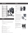
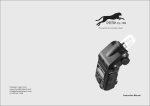
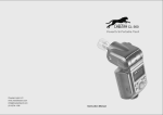
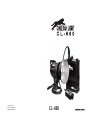
Cheetah Light LLC.
www.cheetahstand.com
[email protected]
CL- 600
CONTENTS
P01
For Your Safety
P01
Caution
P02
Names of Parts
Battery Module
Control Module
Flash Head
AC Charger
P03
What’s in the Box
P03
Operation
Battery
Mounting and Detaching the Reflector
Installing and Detaching the Flash Tube
P06
Using the Flash
Power Management
Foreword
Power Level Adjusting
Thank you for purchasing this product.
M Mode: Manual Flash
Before using this product, please read this user manual carefully in order to ensure
S1 Mode: S1 Slave Triggering Mode
your safety and the proper operation of this product. Keep for future reference.
S2 Mode: S2 Slave Triggering Mode
Modeling Lamp On / Off
Wireless power-control flash CL600 is designed to provide a lightweight,
Sound Prompt Beep
portable, easy-to-use, multi-functional, and reliable flash lighting solution for outdoor
shooting. It fits wedding, art, portrait, and commercial photography. This portable
Wireless Control Function
flash offers:
Sync Triggering
1. Built-in wireless power adjusting and flash triggering
P08
2. Large-capacity 8000mAh lithium battery (LiFePO4)
Over-Temperature Protection
3. Full battery provides 450 full power flashes for CL600
4. Recycle to full power in 2.5 second for CL600
5. User-replaceable battery module
6. Power adjusts from 1/1 to 1/32 with auto power discharge
7. Stable color temperature at 5600±200k
8. LCD display on a concise and modern panel
9. Built-in fan to prevent overheating.
Protection Function
Other Protection
P09
Technical Data
Maintenance
For your safety
Name of Parts
DO NOT disassemble or modify
Battery Module
This product contains high-voltage components. Failure to observe this precaution could result in
Flash Head
electric shock or product malfunction. Should the product break open as the result of a fall or other
04
accident, send the defective back to an authorized maintenance center.
Keep dry
01
Do not handle with wet hands, immerse into water, or expose to rain. Failure to observe this
02
precaution could damage this product.
03
21
18
24
23
Keep out of the reach of children
20
19
This product contains small parts that may pose a choking hazard. Should any part of this device be
swallowed accidently, consult a physician immediately.
22
25
Do not expose to high temperature
Do not leave or store this product in high temperature conditions. Failure to observe this precaution
Control Module
could cause fire or damage the housing or internal parts.
17
AC Charger
08
14
13
06
05
27
10
CL-600
09
Caution
07
NEVER touch the flash tube or the modeling lamp with bare hands. Please wear insulated gloves
15
16
12
28
11
29
before replacing any of them.
Do not look directly at the flash tube when in use or it may cause eye pain or blurring vision.
Turn the battery pack off and disconnect the flash head from the battery pack when they will not be
used. If not, the battery pack will remain in charging state and consume electricity.
Avoid sudden impact. This could damage the flash tube and the battery pack.
Do not use this product in serve cold, damp, or high temperature conditions.
Battery Module
Control Module
Flash Head
AC Charger
01. Electrodes
05. Flash Output Dimmer
18. Bayonet Mount Lock
27. Charging Indicator
02. Fuses
06. LCD Panel
19. Angle Adjusting Handle
28. AC Power Plug
03. Charging Socket
07. Test Button (TEST) / Flash
20. Umbrella Input
29. Charging Plug
04. Lock
Ready Indicator
21. Power Input Socket
08. Light Sensor
22. Mount Bracket
09. Mode Selection Button (MODE)
23. Flash Tube
10. Power Switch
24. LED Modeling Lamp
11. Buzz Button (BUZZ)
25. Reflector
12. Modeling Lamp Switch (LAMP)
26. Power Connection Line
13. Battery Level Indicator
14. Sound Beep Outlet
15. Sync Cord Jack
16. Wireless Control Port
17. Power Output Socket
26
-1-
-2-
Operation
What’s in the Box
No. Name
Unit Quantity
Installation and Detachment of Battery Module
Installation
1
Flash head
PCS
1
Place the battery pack on a horizontal
2
Battery Module
PCS
1
table. Put the control module over the
3
Control Module
PCS
1
4
AC Charger
PCS
1
hands. Check and ensure the locks
5
Wireless Power-control Flash Trigger
Pair
1
are in position.
6
Aluminum Case
PCS
1
7
Soft Cap
PCS
1
8
Lamp Cover
PCS
1
9
Shoulder Bag
PCS
1
10 Power Connection Line
PCS
1
Standard Reflector
PCS
1
A
battery module and push it down.
Fasten the locks on both sides with
Detachment
With Part A pressed down, open the locks on the both sides.
Charging
Insert the Charging Plug (29) of the AC charger into the
Charging Socket (03) of the battery pack. Connect one end
of the Charger Power Cable to the AC Power Plug (28) and
the other end to the AC power supply. Make sure sound
11
connections and the battery pack starts to be charging. For
the charging status, see the instructions on the AC charger.
The battery module can be separated from the control
Operation
module during charging. Therefore, purchasing another
battery module means unlimited interchanges and
numerous flashes with one on charging and one on
working.
Battery
This battery pack adopts LiFePO4 battery. It has a long battery life and 2000 charge-and-discharge times.
NOTE: To ensure the battery service life, you are not advised to use
the battery pack when it is being charged.
It is safe and reliable. The inner circuit is built in with protection against over-charging, over-discharge,
over-current, and short circuit.
Mounting and Detaching the Reflector
This battery pack needs four hours’ charging time.
The flash head adopts a Bowens-style bayonet mount to
install the Reflector (25). You can detach the reflector to
Caution
add other lighting accessories found in studios, e.g.
Avoid excessive impacts and shocks.
beauty dish and softbox.
This product is not water-proof. DO NOT expose it to fog or immerse into water.
To detach the reflector, press the Bayonet Mount Lock
(18) and hold for seconds till you rotate the reflector and
Keep this product out of reach of children.
detach it.
DO NOT keep this battery pack in charging state for over 24 hours.
Keep this product in cool, dry, and draughty places.
DO NOT put this product beside or into fire.
Batteries out of service must be handled according to local regulations.
DO NOT fire the flash head when in charging.
If the battery pack had ceased using for more than 6 months, please give it a full charge before using it.
-3-
-4 -
Operation
Using the Flash
Installing and Detaching the Flash Tube
1. Power Management
1. Turn the power off
3. Wear a pair of insulated
Press the Power Switch (10) and hold for a second to turn the battery pack on or off. Please power it off
and remove all power
gloves and loosen the
if it will not be used for an extended period of time.
cables.
iron wire on the tube.
If the battery pack is powered on but the Power Connection Line (26) is not well connected, the battery
2. Detach the reflector.
pack will auto power off after 10 seconds.
If the battery pack is powered on and the Power Connection Line (26) is well connected, the battery pack
will auto power off after 3 hours’ idle operation.
Note: Before unpluging the Power Connection Line (26), please turn the battery pack off.
4. Keep a balanced
5. Target a new tube directly
hold on the two feet
towards the two copper
of the tube and pull
outlets and slightly push
it out gently.
it in.
2. Power Level Adjusting
You can adjust the power level from 1/32 power to 1/1 full power in 1/3 stop increments. Use a hand-held
flash meter to determine the required flash output to obtain a correct flash exposure.
Rotate the Flash Output Dimmer (05) to adjust the power level. The following table makes it easier to see
how the stop changes in terms of f/stop when you increase or decrease the flash output:
Figures displayed when reducing flash output level→
6. Twine the iron wire
to fix the new tube.
7. Target the reflector
towards the bayonet
of flash head.
8. Rotate the reflector
until it is securely
fixed.
1/1
1/1-0.3
1/1-0.7
1/2+0.7
1/2+0.3
1/2
1/2-0.3
1/2-0.7
1/4+0.7
1/4+0.3
1/4
OF
←Figures displayed when increasing flash output level
Note: When “OF” is shown on the LCD display, it means no flash output and flash firing is turned off.
3. M Mode: Manual Flash
Press Mode Selection Button (09) to enter M mode. In this mode, you can use a radio trigger to fire the
flash. Before shooting, adjust the power level of the flash and the settings of your camera. When you
press the camera shutter-release button, the flash will fire. Slave triggering mode is not available in M
mode.
4. S1 Mode: S1 Slave Triggering Mode
Press Mode Selection Button (09) to enter S1 mode. In this mode, the flash can function as a slave flash
for creating multiple lighting effects. It is applicable to work under ambient light situations, but direct
sunlight or other direct strong lights may reduce the sensitivity of the light sensor.
In S1 mode, the flash will fire when the master flash fires, the same result as that by the use of a radio
trigger.
5. S2 Mode: S2 Slave Triggering Mode
Press Mode Selection Button (09) to enter S2 mode. In this mode, the flash can function as a slave flash
for creating multiple lighting effects. It is applicable when using a TTL master flash. It can work under
ambient light situations, but direct sunlight or other direct strong lights may reduce the sensitivity of the
light sensor.
-5-
-6-
Using the Flash
Protection Function
In S2 mode, the flash will ignore a single “preflash” from the master flash and will only fire in response to
the second, actual flash from the master.
1. Over-Temperature Protection
To avoid overheating and deteriorating the flash head, DO NOT fire more than 100 continuous flashes in
fast succession at 1/1 full power. After 100 continuous flashes, allow a rest time of at least 10 minutes.
6. Modeling Lamp On / Off
This flash head is equipped with LED modeling lamp.
To turn the modeling lamp on or off, press the Modeling Lamp Switch (12). When it lights up,
will be
shown on the LCD display.
The modeling lamp will be off automatically after 15 minutes so as to prevent overheating. Allow a rest
time of 5 minutes before you turn it on.
If you fire more than 100 continuous flashes and then fire more flashes in short intervals, the inner
7. Sound Prompt Beep
Number of flashes that will active over-temperature protection:
over-temperature protection function may be activated and make the recycling time about 10 to 15
seconds. If this occurs, allow a rest time of about 10 minutes, and the flash kit will then return to normal.
When the over-temperature protection is started,
will be shown on the LCD display.
The battery pack is built in with a buzzer to prompt you that the flash kit is ready for firing. You can press
the Buzz Button (11) to enable or disable the sound prompt beep.
When the buzzer is enabled,
will be shown on the LCD display.
Power Output Level
Number of Flashes (Approx.)
1/1
100
8. Wireless Control Function
1/2
150
The battery pack is built in with a Wireless Control Port (16) so that you can wirelessly control the flash
kit in terms of power level, modeling lamp & buzzer on/off and achieve flash triggering.
To control the flash kit wirelessly, the included CL-Tx/Rx flash trigger is required. Insert its receive end
into the Wireless Control Port (16) on the battery pack and mount the transmit end onto the camera
hotshoe. Settings made on the hotshoe-mounted transmit and receive ends will be wirelessly
communicated to the flash and battery pack. Then you can press the camera shutter button to trigger the
flash. Also, you can hold the transmit end in your hand to achieve wireless control.
When the battery pack receives wireless signals,
will be shown on the LCD display.
For full instructions on the use of CL-Tx/Rx flash trigger, see its user manual.
1/4
200
1/8
300
1/16,1/32
400
2. Other Protection
The system provides real-time protection to secure the device and your safety. The following lists prompts
for your reference:
9. Sync Triggering
The Sync Cord Jack (15) is a φ3.5mm plug. Insert a trigger plug here and the flash will be fired
synchronously with the camera shutter.
Prompts on LCD Panel
Meaning
E0
A failure occurs on the temperature sensor inside the battery pack.
Please send this kit to a maintenance center.
E1
A failure occurs on the recycling system so that the flash cannot fire.
Please restart the battery pack. If the problem still exists, please send this
kit to a maintenance center.
E2
The system gets excessive heat. Please allow a rest time of 10 minutes.
E3
The voltage on two outlets of the flash tube is too high. Please send this
product to a maintenance center.
-7-
-8-
Technical Data
Model
CL600
Max. Power
600W/S
Guide No. (m ISO 100)
68
Battery
LiFePO4 (12.8V / 8000mAh)
Recycling Time at 1/1 Full Power
2.5 second
Full Power Flashes
Approx. 450
Flash Duration
1/800 to 1/2000 second
Power Adjusting
16 steps from 1/32 to 1/1
LED Modeling Lamp
12W
Color Temperature
5600K±200K
Voltage of Charger
AC100-240V / 50-60Hz
Battery Pack Size
17cm×8cm×26cm
Battery Pack Weight
Approx. 2.98kg
Flash Head Weight
Approx.0.96kg
Weight with the Case
Approx. 7.8kg
Battery Unit Size &Weight
17cm×8cm×10.7cm /1.71kg
Maintenance
Shut down the system immediately should abnormal operation be detected.
Avoid sudden impacts and the flash kit should be dedusted regularly.
It is normal for the flash tube to be warm when in use. Avoid continuous flashes if unnecessary.
Maintenance of the flash head must be performed by our authorized maintenance center which can
provide original parts. The flash tube is user replaceable. Replacement tubes can be obtained from the
manufacturer.
This flash kit, except the consumables e.g. flash tube and modeling lamp, is supported with a one-year
warranty.
Unauthorized service will void the warranty.
If the product had failure or was wetted, do not use it until it is repaired by professionals.
Changes made to the specifications or designs may not be reflected in this manual.
-9-