1
Installation Instructions
PowerFlex® 7000 Medium Voltage AC Drive Air-Cooled
("B" Frame)—ForGe Control
Publication 7000-IN007E-EN-P
Important User Information
Read this document and the documents listed in the additional resources section about installation, configuration, and
operation of this equipment before you install, configure, operate, or maintain this product. Users are required to
familiarize themselves with installation and wiring instructions in addition to requirements of all applicable codes, laws,
and standards.
Activities including installation, adjustments, putting into service, use, assembly, disassembly, and maintenance are required
to be carried out by suitably trained personnel in accordance with applicable code of practice.
If this equipment is used in a manner not specified by the manufacturer, the protection provided by the equipment may be
impaired.
In no event will Rockwell Automation, Inc. be responsible or liable for indirect or consequential damages resulting from the
use or application of this equipment.
The examples and diagrams in this manual are included solely for illustrative purposes. Because of the many variables and
requirements associated with any particular installation, Rockwell Automation, Inc. cannot assume responsibility or
liability for actual use based on the examples and diagrams.
No patent liability is assumed by Rockwell Automation, Inc. with respect to use of information, circuits, equipment, or
software described in this manual.
Reproduction of the contents of this manual, in whole or in part, without written permission of Rockwell Automation,
Inc., is prohibited.
Throughout this manual, when necessary, we use notes to make you aware of safety considerations.
WARNING: Identifies information about practices or circumstances that can cause an explosion in a hazardous environment,
which may lead to personal injury or death, property damage, or economic loss.
ATTENTION: Identifies information about practices or circumstances that can lead to personal injury or death, property
damage, or economic loss. Attentions help you identify a hazard, avoid a hazard, and recognize the consequence.
IMPORTANT
Identifies information that is critical for successful application and understanding of the product.
Labels may also be on or inside the equipment to provide specific precautions.
SHOCK HAZARD: Labels may be on or inside the equipment, for example, a drive or motor, to alert people that dangerous
voltage may be present.
BURN HAZARD: Labels may be on or inside the equipment, for example, a drive or motor, to alert people that surfaces may
reach dangerous temperatures.
ARC FLASH HAZARD: Labels may be on or inside the equipment, for example, a motor control center, to alert people to
potential Arc Flash. Arc Flash will cause severe injury or death. Wear proper Personal Protective Equipment (PPE). Follow ALL
Regulatory requirements for safe work practices and for Personal Protective Equipment (PPE).
Allen-Bradley, Rockwell Software, Rockwell Automation, and TechConnect are trademarks of Rockwell Automation, Inc.
Trademarks not belonging to Rockwell Automation are property of their respective companies.
Summary of Changes
This manual contains new and updated information.
New and Updated
Information
This table contains the changes made to this revision.
Topic
Page
Replace “Tachometer” with “Encoder”
Throughout
Added HPTC information to Topology section
11
Updated “When is an Encoder Required?” section and table
74
Replaced Encoder Selection table
75
Added HPTC information to Drive Torque Capabilities table
76
Updated Typical Application Load Torque Profiles
77
Updated Speed Regulator Bandwidth
92
Updated Torque Regulator Bandwidth
92
Inserted Torque Accuracy with HPTC
92
Added Polish to list of available Languages
93
Added “Dual-port Ethernet/IP” to Communications Protocols
94
Rockwell Automation Publication 7000-IN007E-EN-P - June 2014
3
Summary of Changes
Notes:
4
Rockwell Automation Publication 7000-IN007E-EN-P - June 2014
Table of Contents
Chapter 1
Important User Information
Who Should Use This Manual . . . . . . . . . . . . . . . . . . . . . . . . . . . . . . . . . . . . . . 7
What Is Not in this Manual. . . . . . . . . . . . . . . . . . . . . . . . . . . . . . . . . . . . . . . . . 7
Manual Conventions . . . . . . . . . . . . . . . . . . . . . . . . . . . . . . . . . . . . . . . . . . . . . . . 8
General Precautions . . . . . . . . . . . . . . . . . . . . . . . . . . . . . . . . . . . . . . . . . . . . . . . . 8
Commissioning Support. . . . . . . . . . . . . . . . . . . . . . . . . . . . . . . . . . . . . . . . . . . . 9
Chapter 2
PowerFlex 7000 Overview
Topology . . . . . . . . . . . . . . . . . . . . . . . . . . . . . . . . . . . . . . . . . . . . . . . . . . . . . . . .
Rectifier Designs . . . . . . . . . . . . . . . . . . . . . . . . . . . . . . . . . . . . . . . . . . . . . . . . .
Configurations . . . . . . . . . . . . . . . . . . . . . . . . . . . . . . . . . . . . . . . . . . . . . . .
Cooling Technology. . . . . . . . . . . . . . . . . . . . . . . . . . . . . . . . . . . . . . . . . . . . . .
Motor Compatibility . . . . . . . . . . . . . . . . . . . . . . . . . . . . . . . . . . . . . . . . . . . . .
Simplified Electrical Diagrams . . . . . . . . . . . . . . . . . . . . . . . . . . . . . . . . . . . .
2400V . . . . . . . . . . . . . . . . . . . . . . . . . . . . . . . . . . . . . . . . . . . . . . . . . . . . . . .
3300/4160V . . . . . . . . . . . . . . . . . . . . . . . . . . . . . . . . . . . . . . . . . . . . . . . . .
6600V . . . . . . . . . . . . . . . . . . . . . . . . . . . . . . . . . . . . . . . . . . . . . . . . . . . . . . .
Operator Interface . . . . . . . . . . . . . . . . . . . . . . . . . . . . . . . . . . . . . . . . . . . . . . .
Basic Configurations . . . . . . . . . . . . . . . . . . . . . . . . . . . . . . . . . . . . . . . . .
11
12
12
14
15
16
16
17
18
19
19
Chapter 3
Drive Installation
Safety and Codes . . . . . . . . . . . . . . . . . . . . . . . . . . . . . . . . . . . . . . . . . . . . . . . . .
Transporting and Siting the Drive . . . . . . . . . . . . . . . . . . . . . . . . . . . . . . . . .
Cabinet Layout and Dimensional Drawings of Drive. . . . . . . . . . . . . . . .
Control/Cabling Cabinet . . . . . . . . . . . . . . . . . . . . . . . . . . . . . . . . . . . . .
IEC Component and Device Designations . . . . . . . . . . . . . . . . . . . . . . . . .
Power Wiring Selection . . . . . . . . . . . . . . . . . . . . . . . . . . . . . . . . . . . . . . .
Cable Insulation. . . . . . . . . . . . . . . . . . . . . . . . . . . . . . . . . . . . . . . . . . . . . .
Installation . . . . . . . . . . . . . . . . . . . . . . . . . . . . . . . . . . . . . . . . . . . . . . . . . . . . . .
Shock Indication Labels. . . . . . . . . . . . . . . . . . . . . . . . . . . . . . . . . . . . . . .
Joining Shipping Splits (3300...4160V and 6600V Heat Pipe Model) .
Installing Exhaust Fans and Air Hoods . . . . . . . . . . . . . . . . . . . . . . . . .
Installation of Redundant Fan Assembly . . . . . . . . . . . . . . . . . . . . . . .
External Ducting. . . . . . . . . . . . . . . . . . . . . . . . . . . . . . . . . . . . . . . . . . . . . . . . .
Power Cabling Access . . . . . . . . . . . . . . . . . . . . . . . . . . . . . . . . . . . . . . . . . . . .
Power Connections . . . . . . . . . . . . . . . . . . . . . . . . . . . . . . . . . . . . . . . . . . . . . .
Power Cabling Installation Requirements . . . . . . . . . . . . . . . . . . . . . .
Power and Control Wiring . . . . . . . . . . . . . . . . . . . . . . . . . . . . . . . . . . . . . . .
Control Cables. . . . . . . . . . . . . . . . . . . . . . . . . . . . . . . . . . . . . . . . . . . . . . .
Encoder Installation Guidelines . . . . . . . . . . . . . . . . . . . . . . . . . . . . . . .
Terminating Customer Cables . . . . . . . . . . . . . . . . . . . . . . . . . . . . . . . .
Grounding Practices. . . . . . . . . . . . . . . . . . . . . . . . . . . . . . . . . . . . . . . . . . . . . .
Guidelines for Drive Signal and Safety Grounds. . . . . . . . . . . . . . . . .
Specifications for Customers and Power Integrators . . . . . . . . . . . . .
Electrical Supplies: Grounded and Ungrounded Systems. . . . . . . . .
Rockwell Automation Publication 7000-IN007E-EN-P - June 2014
21
21
21
22
36
36
37
39
39
40
45
49
50
51
55
55
58
58
58
61
62
63
63
63
5
Table of Contents
Ground Bus . . . . . . . . . . . . . . . . . . . . . . . . . . . . . . . . . . . . . . . . . . . . . . . . . . 64
Interlocking. . . . . . . . . . . . . . . . . . . . . . . . . . . . . . . . . . . . . . . . . . . . . . . . . . . . . . 64
Chapter 4
Pre-Commissioning Responsibilities
Inspection and Verification . . . . . . . . . . . . . . . . . . . . . . . . . . . . . . . . . . . . . . .
Pre-Commissioning Responsibilities . . . . . . . . . . . . . . . . . . . . . . . . . . . . . . .
Pre-Commissioning Checklist . . . . . . . . . . . . . . . . . . . . . . . . . . . . . . . . . . . . .
Additional Required Resources . . . . . . . . . . . . . . . . . . . . . . . . . . . . . . . . . . . .
Technical Publications and Manuals . . . . . . . . . . . . . . . . . . . . . . . . . . . . . . .
65
66
67
71
71
Appendix A
General Reference
Torque Requirements for Threaded Fasteners . . . . . . . . . . . . . . . . . . . . . .
Preventative Maintenance Schedule . . . . . . . . . . . . . . . . . . . . . . . . . . . . . . . .
Encoder Usage . . . . . . . . . . . . . . . . . . . . . . . . . . . . . . . . . . . . . . . . . . . . . . . . . . .
When is an Encoder Required? . . . . . . . . . . . . . . . . . . . . . . . . . . . . . . . .
PowerFlex 7000 Drive Performance (Torque Capabilities). . . . . . . . . . .
Glossary of Terms . . . . . . . . . . . . . . . . . . . . . . . . . . . . . . . . . . . . . . . . . . . . . . . .
73
74
74
74
76
77
Appendix B
Meggering
Drive Meggering . . . . . . . . . . . . . . . . . . . . . . . . . . . . . . . . . . . . . . . . . . . . . . . . .
Meggering the PowerFlex 7000 . . . . . . . . . . . . . . . . . . . . . . . . . . . . . . . .
Meggering Procedures . . . . . . . . . . . . . . . . . . . . . . . . . . . . . . . . . . . . . . . . . . . .
Required Equipment. . . . . . . . . . . . . . . . . . . . . . . . . . . . . . . . . . . . . . . . . .
Procedure . . . . . . . . . . . . . . . . . . . . . . . . . . . . . . . . . . . . . . . . . . . . . . . . . . . .
79
79
80
80
80
Appendix C
Line & Load Cable Sizes
Max. Line Cable Sizes. . . . . . . . . . . . . . . . . . . . . . . . . . . . . . . . . . . . . . . . . . . . . 85
Max. Load Cable Sizes . . . . . . . . . . . . . . . . . . . . . . . . . . . . . . . . . . . . . . . . . . . . 88
Appendix D
Specifications
6
Specifications . . . . . . . . . . . . . . . . . . . . . . . . . . . . . . . . . . . . . . . . . . . . . . . . . . . . 91
Rockwell Automation Publication 7000-IN007E-EN-P - June 2014
Chapter
1
Important User Information
This document provides procedural information for installing the PowerFlex
7000 medium voltage “B” Frame drives (heat sink and heat pipe models). This
document also includes specific information regarding customer responsibilities
prior to commissioning.
Who Should Use This Manual
This manual is intended for use by personnel familiar with medium voltage and
solid-state variable speed drive equipment. The manual contains material that
enables qualified engineering personnel to install the drive system.
What Is Not in this Manual
This manual provides information specific to installing and configuring the
PowerFlex 7000 “B” Frame drive. The following topics are covered in other
manuals in the next paragraph:
• Physically transporting or siting the drive cabinetry
• Commissioning-specific processes and configuration, as managed by a
Rockwell Automation commissioning engineer
• Details concerning the operator interface, or configuring drive parameters
• Dimensional and electrical drawings generated for each customer’s order
• Spare parts lists compiled for each customer’s order
• Troubleshooting potential usage problems
Refer to the following documents for additional product detail or instruction
relating to PowerFlex 7000 “B” Frame drives:
• Drive-specific Technical Specifications
• Transportation and Handling Procedures: receiving and handling
instructions for Medium Voltage variable frequency drive and related
equipment
• Installation Guide: detailed installation and pre-commissioning
procedures and information
• Commissioning Guide: required procedures and checklists for Rockwell
Automation field service engineers
• Drive-specific User Manual: instructions for daily and recurring drive
usage or maintenance tasks
• Drive-specific Technical Data: additional troubleshooting, parameters,
and specification information for MV variable frequency drives
Rockwell Automation Publication 7000-IN007E-EN-P - June 2014
7
Chapter 1
Important User Information
Rockwell Automation provides the site- and installation-specific electrical and
design information for each drive during the order process cycle. If they are not
available on-site with the drive, contact Rockwell Automation.
If you have multiple drive types or power ranges, ensure you have the correct
documentation for each specific PowerFlex 7000 product:
• “A” Frame for lower power air-cooled configurations (up to approximately
1250 hp / 933 kW)
• “B” Frame for higher-power, air-cooled configurations (heat sink or heat
pipe models)
• “C” Frame for all liquid-cooled configurations
Manual Conventions
This manual uses a variety of symbols to indicate specific types of information.
WARNING: Warnings indicate where people may be hurt if users do not follow
procedures properly.
ATTENTION: Cautions indicate where machinery damage or economic loss may
occur if users do not follow procedures properly.
Both of the above symbols could indicate:
• A possible trouble spot
• Tell what causes the trouble spot
• Give the result of an improper action
SHOCK HAZARD: This symbol indicates a potential electrical shock hazard on a
component or printed circuit board
General Precautions
ATTENTION: This drive contains ESD (Electrostatic Discharge) sensitive parts
and assemblies. Static control precautions are required when installing, testing,
servicing or repairing this assembly. Component damage may result if ESD
control procedures are not followed. If you are not familiar with static control
procedures, refer to Allen-Bradley publication 8000-4.5.2, “Guarding Against
Electrostatic Damage” or any other applicable ESD protection handbook.
ATTENTION: An incorrectly applied or installed drive can result in component
damage or a reduction in product life. Wiring or application errors, such as,
undersizing the motor, incorrect or inadequate AC supply, or excessive ambient
temperatures may result in malfunction of the system.
8
Rockwell Automation Publication 7000-IN007E-EN-P - June 2014
Important User Information
Chapter 1
ATTENTION: Only personnel familiar with the PowerFlex 7000 Adjustable
Speed Drive (ASD) and associated machinery should plan or implement the
installation, start-up and subsequent maintenance of the system. Failure to
comply may result in personal injury and/or equipment damage.
Commissioning Support
After installation, Rockwell Automation Medium Voltage Support is responsible
for commissioning support and activities in the PowerFlex 7000 product line.
Phone: 519-740-4790
Option 1 for technical and option 4 for commissioning questions
[email protected] or
[email protected]
Rockwell Automation support includes, but is not limited to:
• quoting and managing product on-site start-ups
• quoting and managing field modification projects
• quoting and managing customer in-house and on-site product training
Rockwell Automation Publication 7000-IN007E-EN-P - June 2014
9
Chapter 1
Important User Information
Notes:
10
Rockwell Automation Publication 7000-IN007E-EN-P - June 2014
Chapter
2
PowerFlex 7000 Overview
The PowerFlex 7000 is a general purpose, stand-alone, medium voltage drive that
controls speed, torque, direction, starting and stopping of standard asynchronous
or synchronous AC motors. It works on numerous standard and specialty
applications such as fans, pumps, compressors, mixers, conveyors, kilns, fanpumps, and test stands in industries such as petrochemical, cement, mining and
metals, forest products, power generation, and water/waste water.
The PowerFlex 7000 meets most common standards from the National Electrical
Code (NEC), International Electrotechnical Commission (IEC), National
Electrical Manufacturers Association (NEMA), Underwriters Laboratories
(UL), and Canadian Standards Association (CSA). It is available with the world’s
most common supply voltages at medium voltage, from 2400...6600V.
The design focus is on high reliability, ease of use, and lower total cost of
ownership.
Topology
The PowerFlex 7000 uses a Pulse Width Modulated (PWM) – Current Source
Inverter (CSI) for the machine side converter as shown in Figure 6. This
topology applies to a wide voltage and power range. The power semiconductor
switches used are easy-to-series for any medium voltage level. Semiconductor
fuses are not required for the power structure due to the current limiting DC link
inductor.
With 6500V PIV rated power semiconductor devices, the number of inverter
components is minimal. For example, only six inverter switching devices are
required at 2400V, 12 at 3300...4160V, and 18 at 6600V.
The PowerFlex 7000 also provides inherent regenerative braking for applications
where the load is overhauling the motor (e.g. downhill conveyors, etc.), or where
high inertia loads (e.g. fans, etc.) are quickly slowed down. The drive uses
Symmetrical Gate Commutated Thyristors (SGCTs) for machine converter
switches, and Silicon-controlled Rectifiers (SCRs) (for 18 Pulse rectifier
configurations) or SGCTs (for Active Front-end [AFE] rectifier configurations)
for the line converter switches.
The PowerFlex 7000 provides a selectable option for enhanced torque control
capabilities and increased dynamic control performance. This High Performance
Torque Control (HPTC) feature delivers 100% torque at zero speed and
provides torque control through zero speed with smooth direction transition.
Rockwell Automation Publication 7000-IN007E-EN-P - June 2014
11
Chapter 2
PowerFlex 7000 Overview
Rectifier Designs
Configurations
The PowerFlex 7000 offers three rectifier configurations for "B" Frame drives:
• Direct-to-Drive (Active Front End [AFE] rectifier with integral line
reactor and Common Mode Choke)
• AFE rectifier with separate isolation transformer
• 18 Pulse with separate isolation transformer
Direct-to-Drive
Direct-to-DriveTM technology does not require an isolation transformer or
multiple rectifier bridges as in Voltage Source Inverter (VSI) topologies offered
by others. The approach is completely different. Instead of multiple uncontrolled
rectifiers, a single AFE rectifier bridge is supplied. The rectifier semiconductors
used are Symmetrical Gate Commutated Thyristors (SGCTs). Unlike the diodes
used in VSI rectifier bridges, SGCTs are turn ed on and off by a gating signal. A
Pulse Width Modulation (PWM) gating algorithm controls the firing of the
rectifier devices, very similar to the control philosophy of the inverter. The gating
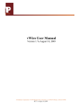
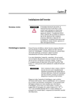
algorithm uses a specific 42 pulse switching pattern (Figure 1) called Selective
Harmonic Elimination (SHE) to mitigate the 5th, 7th, and 11th harmonic
orders.
Figure 1 - Typical PWM switching pattern , line voltage waveform
A small integral line reactor and capacitor addresses the high harmonic orders
(13th and above) and provides virtually sinusoidal voltage and current waveforms
back to the distribution system. This delivers excellent line-side harmonic and
power factor performance to meet IEEE 519-1992 requirements and other global
harmonic standards, while still providing a simple, robust power structure that
maximizes uptime by minimizing the number of discrete components and the
number of interconnections required.
A Common Mode Choke (CMC) mitigates the common mode voltage seen at
the motor terminals, so standard (non-inverter duty rated) motors and motor
cables can be used, making this technology ideal for retrofitting existing motor
applications.
12
Rockwell Automation Publication 7000-IN007E-EN-P - June 2014
PowerFlex 7000 Overview
Chapter 2
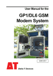
Figure 2 - 3300/4160V AFE Rectifier (Direct-to-Drive)
LINE CONVERTER
C OMMON MODE CHOKE
L+
MACHINE CONVERTER
M+
SGCTs
SGCTs
LR
U (T1)
V (T2)
W (T3)
L-
M-
AFE Rectifier with Separate Isolation Transformer
For applications when the line voltage is higher than the motor voltage, a
transformer is required for voltage matching. In this case, providing an AFE
rectifier with a separate isolation transformer is ideal. The isolation transformer
provides the input impedance (replaces the requirement for an integral line
reactor) and addresses the common mode voltage (replaces the requirement for a
CMC that is supplied in the Direct-to-Drive rectifier configuration). However,
the AFE rectifier, its operation, and advantages are the same as the Direct-toDrive configuration.
Figure 3 - 3300/4160 AFE Rectifier with separate isolation transformer)
LINE CONVERTER
REMOTE
ISTX
M+
SGCTs
SGCTs
1U
1V
1W
MACHINE CONVERTER
DC LINK
L+
2U (X1)
U (T1)
2V (X2)
V (T2)
2W (X3)
W (T3)
L-
M-
Rockwell Automation Publication 7000-IN007E-EN-P - June 2014
13
Chapter 2
PowerFlex 7000 Overview
18 Pulse Rectifier with Separate Isolation Transformer
For high power, constant torque applications and/or when the line voltage is
higher than the motor voltage, a transformer is required for voltage matching.
The 18 Pulse rectifier uses SCRs instead of the SGCTs used for an AFE rectifier.
When used for high power and constant torque applications, the 18 Pulse
rectifier has lower losses than the AFE rectifier, making it ideal for the highest
power requirements. The 18 Pulse isolation transformer provides the required
input impedance and addresses common mode voltage just like the separate
isolation transformer used with the AFE rectifier. However, instead of a PWM
switching pattern and a single rectifier bridge, the 18 Pulse configuration
mitigates line side harmonics through harmonic current cancellation in the
isolation transformer phase shifted secondary windings. The inverter is the same
configuration for all available rectifier options.
Figure 4 - 3300/4160V 18 Pulse rectifier
LINE CONVERTER
ISTX
DC LINK
L+
M+
4U (Z1)
4V (Z2)
4W (Z3)
MACHINE CONVERTER
SGCTs
SCRs
U (T1)
3U (Y1)
3V (Y2)
3W (Y3)
V (T2)
W (T3)
2U (X1)
2V (X2)
2W (X3)
L-
Cooling Technology
M-
These VFDs are supplied with heat sinks for low and mid-power configurations
and heat pipes for high-power configurations. While both configurations draw
heat away from the semiconductors, heat pipes are bigger, more efficient, and
require larger fans and airflow.
Information and graphics in this manual show both configurations.
14
Rockwell Automation Publication 7000-IN007E-EN-P - June 2014
PowerFlex 7000 Overview
Motor Compatibility
Chapter 2
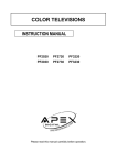
The PowerFlex 7000 achieves near-sinusoidal current and voltage waveforms to
the motor, resulting in no significant additional heating or insulation stress.
Temperature rise in the motor connected to the VFD is typically 3 °C (5.5 °F)
higher compared to across-the-line operation. Voltage waveform has dv/dt of less
than 10 V/μs. The peak voltage across the motor insulation is the rated motor
RMS voltage divided by 0.707.
Reflected wave and dv/dt issues often associated with voltage source inverter
(VSI) drives are a non-issue with the PowerFlex 7000. Figure 5 shows typical
motor waveforms. The drive uses a selective harmonic elimination (SHE) pattern
in the inverter to eliminate major order harmonics, plus a small output capacitor
(integral to the drive) to eliminate harmonics at higher speeds.
Standard motors are compatible without de-rating, even on retrofit applications.
Motor cable distance is virtually unlimited. Rockwell Automation has tested this
technology for controlling motors up to 15 km (9.3 mi) away from the drive.
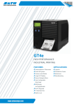
Figure 5 - Motor waveforms @ full load, full speed
300.00
Arms
200.00
CURRENT
100.00
0.00
-100.00
-200.00
-300.00
10.00K
Vrms
7.50K
5.00K
VOLTAGE
2.50K
0.00K
-2.50K
-5.00K
-7.50K
-10.00K
100.00
110.00
120.00
TIME (ms)
Rockwell Automation Publication 7000-IN007E-EN-P - June 2014
130.00
140.00
150.00
15
Chapter 2
PowerFlex 7000 Overview
2400V
Simplified Electrical
Diagrams
Figure 6 - 2400V – AFE Rectifier, Configuration #1 – Direct-to-Drive
LINE CONVERTER
C OMMON MODE CHOKE
L+
MACHINE CONVERTER
M+
SGCTs
SGCTs
LR
U (T1)
V (T2)
W (T3)
L-
M-
Figure 7 - 2400V – AFE Rectifier, Configuration #2 – Separate Isolation Transformer
LINE CONVERTER
REMOTE
ISTX
MACHINE CONVERTER
DC LINK
L+
M+
SGCTs
SGCTs
2U (X1)
U (T1)
1V
2V (X2)
V (T2)
1W
2W (X3)
W (T3)
1U
L-
M-
Figure 8 - 2400V - Configuration #3 - 18 Pulse
LINE CONVERTER
ISTX
DC LINK
L+
M+
4U (Z1)
4V (Z2)
4W (Z3)
MACHINE CONVERTER
SGCTs
SCRs
U (T1)
3U (Y1)
3V (Y2)
3W (Y3)
V (T2)
W (T3)
2U (X1)
2V (X2)
2W (X3)
L-
16
M-
Rockwell Automation Publication 7000-IN007E-EN-P - June 2014
PowerFlex 7000 Overview
Chapter 2
3300/4160V
Figure 9 - 3300/4160V – AFE Rectifier, Configuration #1 – Direct-to-Drive
LINE CONVERTER
C OMMON MODE CHOKE
L+
MACHINE CONVERTER
M+
SGCTs
SGCTs
LR
U (T1)
V (T2)
W (T3)
L-
M-
Figure 10 - 3300/4160V – AFE Rectifier, Configuration #2 – Separate Isolation Transformer
LINE CONVERTER
REMOTE
ISTX
MACHINE CONVERTER
DC LINK
L+
M+
SGCTs
SGCTs
1U
1V
1W
2U (X1)
U (T1)
2V (X2)
V (T2)
2W (X3)
W (T3)
L-
M-
Figure 11 - 3300/4160V - Configuration #3 - 18 Pulse
LINE CONVERTER
ISTX
DC LINK
L+
M+
4U (Z1)
4V (Z2)
4W (Z3)
MACHINE CONVERTER
SGCTs
SCRs
U (T1)
3U (Y1)
3V (Y2)
3W (Y3)
V (T2)
W (T3)
2U (X1)
2V (X2)
2W (X3)
L-
M-
Rockwell Automation Publication 7000-IN007E-EN-P - June 2014
17
Chapter 2
PowerFlex 7000 Overview
6600V
Figure 12 - 6600V – AFE Rectifier, Configuration #1 – Direct-to-Drive
LINE CONVERTER
MACHINE CONVERTER
C OMMON MODE CHOKE
L+
M+
SGCTs
SGCTs
LR
U (T1)
V (T2)
W (T3)
L-
M-
Figure 13 - 6600V – AFE Rectifier, Configuration #2 – Separate Isolation Transformer
LINE CONVERTER
REMOTE
ISTX
M+
SGCTs
SGCTs
1U
1V
1W
MACHINE CONVERTER
DC LINK
L+
2U (X1)
U (T1)
2V (X2)
V (T2)
2W (X3)
W (T3)
L-
M-
Figure 14 - 6600V - Configuration #3 - 18 Pulse
ISTX
LINE CONVERTER
L+
DC LINK
M+
4U (Z1)
4V (Z2)
4W (Z3)
MACHINE CONVERTER
SGCTs
SCRs
U (T1)
3U (Y1)
3V (Y2)
3W (Y3)
V (T2)
W (T3)
2U (X1)
2V (X2)
2W (X3)
L-
18
M-
Rockwell Automation Publication 7000-IN007E-EN-P - June 2014
PowerFlex 7000 Overview
Operator Interface
Chapter 2
The HMI Interface Board is an HMI-enabling device for the PowerFlex 7000
drive. It allows the user to acquire all the necessary executable tools,
documentation and reports required to commission, troubleshoot and maintain
the drive.
Via the HMI Interface Board, the user can choose the style and size of the desired
Windows-based operator terminal to interact with the drive (e.g. PanelView CE
terminal, laptop, or desktop computer). The HMI Interface Board removes past
issues with compatibility between the drive and configuration tools, as all the
necessary tools are acquired from the drive.
The HMI Interface Board is well suited for applications that require remote
placement of the operator terminal and remote maintenance.
Figure 15 - Operator Interface
Basic Configurations
There are three basic configurations for the HMI Interface Board.
Remote-mounted HMI
The HMI is not mounted in the traditional location on the low voltage door of
the Variable Frequency Drive (VFD). A remote mounting plate, complete with
E-Stop push button, and HMI is supplied loose for the customer to mount
wherever desired. The HMI connects to the VFD via a hardwired Ethernet cable.
There is no functional distance limitation.
Rockwell Automation Publication 7000-IN007E-EN-P - June 2014
19
Chapter 2
PowerFlex 7000 Overview
This is ideal for non-PLC users wanting to control and monitor remotely (e.g. at
the driven machine, control room, etc.). Also ideal for customers having policies
in place to control access to medium voltage equipment and the associated
requirements of PPE when using the operator interface at the VFD, etc.
Locally-mounted HMI
Similar to the existing PanelView 550, the HMI is mounted on the LV door of
the VFD. There is also a service access port (RJ-45 connector) on the LV door.
No HMI supplied
A service access port (RJ-45 connector) is located on the LV door of the VFD.
Customers use their own laptop as the HMI. All programs required to use the
laptop as the HMI are stored in the VFD. Their laptop is connected to the VFD
via a hardwired Ethernet cable, when required. This is ideal for unmanned sites,
where a dedicated HMI is not required.
See Publication 7000-UM201_ for detailed instruction for the HMI Interface
Board.
20
Rockwell Automation Publication 7000-IN007E-EN-P - June 2014
Chapter
3
Drive Installation
This section details the processes for connecting cabinets and installing physical
components such as fan hoods, as well as installing cabling, grounding, and
interlocking the unit(s). Refer to the Transportation & Handling Guide for
PowerFlex 7000 Medium Voltage Drives for details regarding siting and leveling
drive cabinetry before continuing with the remaining installation tasks
(7000-IN008_-EN-P).
Where appropriate, separate diagrams and instructions are available for both the
heat sink and the heat pipe “B” Frame models. Assume any “B” Frame diagram
not specifically identified as a heat pipe model represents a heat sink model.
Safety and Codes
Transporting and Siting the
Drive
ATTENTION: The CEC, NEC, or local codes outline provisions for safely installing
electrical equipment. Installation must comply with specifications regarding
wire type, conductor sizes, branch circuit protection and disconnect devices.
Failure to do so may result in personal injury and/or equipment damage.
Follow all guidelines for siting the components before continuing with these
installation procedures.
There may be some variation in the process depending on the type and number of
drive components in your particular installation. Follow the correct procedures
recommended for your particular components, and contact your Rockwell
Automation sales or service representative if you have any questions during any
part of the installation process.
Cabinet Layout and
Dimensional Drawings of
Drive
Generic dimensional drawings for the “B” Frame drives will be available in a
forthcoming PowerFlex 7000 Reference Manual revision. Drawings specific to
your unit and your installation are available as a package with your unit. For
additional copies, or if you have questions, contact your Rockwell Automation
sales representative.
Rockwell Automation Publication 7000-IN007E-EN-P - June 2014
21
Chapter 3
Drive Installation
Control/Cabling Cabinet
The following diagrams illustrate the medium voltage area, located in the
control/cabling cabinet behind the low voltage compartment and with barriers
removed.
Note: Heat pipes are only available within AFE rectifier “B” Frame models.
Figure 16 - Cabling cabinet for AFE rectifier (heat sink model)
Hall Effect Sensors
Grounding Network
(For use with Isolation Transformer)
or
Ground Filter
(For use with Line reactor)
Sensing Boards
Line Terminals
Motor Terminals
Motor Filter Capacitors
Current Transformers
Surge Arresters
22
Rockwell Automation Publication 7000-IN007E-EN-P - June 2014
Drive Installation
Chapter 3
Figure 17 - Cabling cabinet for AFE rectifier (heat pipe model)
Grounding Network (For use
with Isolation Transformer)
or
Ground Filter (For use with Line
Reactor)
Surge Arresters
Motor Terminals
Hall Effect Current
Sensors
Voltage Sensing Boards
Line Terminals
Current Transformers
Zero Sequence
Current transformer
(used with Line
Reactor)
Rockwell Automation Publication 7000-IN007E-EN-P - June 2014
23
Chapter 3
Drive Installation
Figure 18 - Cabling Cabinet for AFE Rectifier (6600V heat pipe RPDTD)
Motor Terminals
Surge Arrestors
Grounding Filter (for
use with Line Reactor)
Hall Effect Current
Sensors
Zero Sequence
Current
Transformer
Current Transformer
Voltage Sensing Boards
Line Terminals
24
Rockwell Automation Publication 7000-IN007E-EN-P - June 2014
Drive Installation
Chapter 3
Figure 19 - Cabling Cabinet for 18 Pulse rectifier (motor filter capacitors not shown)
Motor Terminals
Hall-effect Sensor
Transient
Suppression
Network
Voltage Sensing
Boards
Hall-effect sensor
Line Terminals
Current
Transformers
Rockwell Automation Publication 7000-IN007E-EN-P - June 2014
25
Chapter 3
Drive Installation
Figure 20 - AC Line Reactor for AFE rectifier with connection cabinet (heat sink model)
Line Terminals
Line Capacitors
Motor Terminals
Zero Sequence
Current
Transformer
(if supplied)
Line Reactor
26
Motor Filter
Capacitors
Rockwell Automation Publication 7000-IN007E-EN-P - June 2014
Drive Installation
Chapter 3
Figure 21 - AC Line Reactor Cabinet (6600V heat pipe RPDTD model)
Fans
Resistors
Line Reactor
Line Reactor Baffle
Rockwell Automation Publication 7000-IN007E-EN-P - June 2014
27
Chapter 3
Drive Installation
Figure 22 - AC Line Reactor with connection cabinet (heat pipe model)
Fans
MOTOR CAPACITORS
LINE CAPACITORS
Capacitors
Resistors
Line Reactor Baffle
Line Reactor
28
Rockwell Automation Publication 7000-IN007E-EN-P - June 2014
Drive Installation
Chapter 3
Figure 23 - Converter cabinet (heat sink model, 2400V version shown)
Ground bus
Differential Pressure
Sensor
Inverter Modules
Isolated Gate Driver Power
Supplies (IGDPS)
Rectifier IGDPS not
required in drives with
SPS boards installed
Rectifier Modules
Note: There may be minor variations in the cabinet layout for different voltage
classes. This installation manual does not show SPS boards installed.
Rockwell Automation Publication 7000-IN007E-EN-P - June 2014
29
Chapter 3
Drive Installation
Figure 24 - Converter cabinet (heat sink model, 3300...4160V version shown)
Differential Pressure
Sensor
Ground bus
Isolated Gate Driver Power
Supplies (IGDPS)
Inverter Modules
Rectifier IGDPS not
required in drives with
SPS boards installed
Rectifier Modules
30
Rockwell Automation Publication 7000-IN007E-EN-P - June 2014
Drive Installation
Chapter 3
Figure 25 - Converter cabinet (heat sink model, 6600V version shown)
Ground bus
Differential Pressure
Sensor
Isolated Gate Driver
Power Supplies
(IGDPS)
Inverter Modules
Rectifier Modules
Rectifier IGDPS not
required in drives with
SPS boards installed
Rockwell Automation Publication 7000-IN007E-EN-P - June 2014
31
Chapter 3
Drive Installation
Figure 26 - Converter Cabinet, 3300...4160V (heat pipe model)
Inverter modules
Ground bus
Isolated Gate
Driver Power
Supplies (IGDPS)
Isolated Gate
Driver Power
Supplies (IGDPS)
Rectifier modules
Figure 27 - Converter Cabinet, 6600V (heat pipe model)
Inverter modules
Isolated Gate
Driver Power
Supplies
(IGDPS)
Isolated Gate
Driver Power
Supplies
(IGDPS)
Rectifier modules
32
Rockwell Automation Publication 7000-IN007E-EN-P - June 2014
Drive Installation
Chapter 3
Figure 28 - DC Link/Fan cabinet with fan control panel (heat sink model)
Ground Bus
AC/DC Converters
Fan Power Disconnect
Single phase control
power transformer
DC Link Inductor
or CMC
(Barrier removed)
Rockwell Automation Publication 7000-IN007E-EN-P - June 2014
33
Chapter 3
Drive Installation
Figure 29 - DC Link/Fan cabinet with panel removed to show CMC (heat pipe model)
Fans
Common Mode
Choke
34
Rockwell Automation Publication 7000-IN007E-EN-P - June 2014
Drive Installation
Chapter 3
Figure 30 - DC Link/Fan cabinet with fan control panel removed to show main cooling fan
Fan
Inlet Ring
Rockwell Automation Publication 7000-IN007E-EN-P - June 2014
35
Chapter 3
Drive Installation
IEC Component and Device
Designations
PowerFlex 7000 electrical drawings use IEC-based conventions, while remaining
compatible with North American ANSI (American National Standards
Institute) standards. Component-identifying symbols on the drawings are
international; each PowerFlex 7000 elementary drawing (ED) set provides a full
listing of these symbols. Each ED set also lists the device designations used on the
drawings and labeling, with explanations.
Wiring identification uses a source/destination wire number convention on point
to point multi-conductor wiring and elsewhere as warranted. The wirenumbering system of unique, single numbers for multi-drop and point to point
wiring is common in general control and power wiring. Wiring that connects
between the sheets, or that ends at one point and starts at another point on a
drawing, has an arrow and drawing reference to indicate the ongoing connection.
The drawing reference indicates the sheet and the X/Y coordinates of the
continuation point. Each drawing set contains a sheet explaining this reference
system. The unique wire numbering system serves as confirmation that you are
tracing the correct wire from sheet to sheet or across a drawing. Wires in multiconductor cables are typically identified by color rather than by number. The
abbreviations used to identify the colors on the drawings are fully identified on a
sheet in the drawing set.
Power Wiring Selection
The following tables show general wire selections common to the PowerFlex
7000 drive installations.
General notes:
• Adherence to the following recommended field power cabling insulation
levels for medium voltage drives ensures easier start-up and operation.
Increase the cable insulation level over the default supplied for an acrossthe-line application with the same rated line-to-line voltage.
• Use either shielded or unshielded cable, based on the requirements of the
distribution system designer and local standards. However, NEC requires
shielded cable for installations above 2 kV.
36
Rockwell Automation Publication 7000-IN007E-EN-P - June 2014
Drive Installation
Chapter 3
Cable Insulation
These tables provide cable insulation requirements for the PowerFlex 7000 “B”
Frame drive.
ATTENTION: Voltage ratings shown in the following tables are peak line-toground. Some cable manufacturers rate voltage line-to-line RMS. Ensure the
cable meets the rating specified in the following tables.
Table 1 - Cable insulation requirements for AFE and 18 Pulse drives with isolation transformer
System Voltage (V, RMS)
Cable Insulation Rating (kV)
(maximum peak line-to-ground)
Line Side
Machine Side
2400
≥4.1
≥2.2
3000
≥5.12
≥2.75
3300
≥5.63
≥3.0
4160
≥7.1
≥3.8
6000
≥10.8
≥5.5
6300
≥11.4
≥5.8
6600
≥11.8
≥6.0
Table 2 - Cable insulation requirements for “Direct-to-Drive” technology
System Voltage (V, RMS)
Cable Insulation Rating (kV)
(maximum peak line-to-ground)
Line Side
Machine Side
2400
≥2.2
≥2.2
3000
≥2.75
≥2.75
3300
≥3.0
≥3.0
4160
≥3.8
≥3.8
6000
≥5.5
≥5.5
6300
≥5.8
≥5.8
6600
≥6.0
≥6.0
Table 3 identifies general wire categories common to the PowerFlex 7000 “B”
Frame drive. Each category has an associated wire group number, used in the
following sections to identify the appropriate wire to use. The table also provides
application and signal examples, along with the recommended type of cable for
each group, and a matrix providing the recommended minimum spacing between
different wire groups run in the same tray or separate conduit.
Rockwell Automation Publication 7000-IN007E-EN-P - June 2014
37
Chapter 3
Drive Installation
Table 3 - Wire group numbers
For tray: Recommended spacing between different wire groups in the same tray
For conduit: Recommended spacing for wire groups in separate conduit — mm (in.)
Wire
Category
Wire
Group
Application
Signal Example
Recommended
Cable
Wire Group
Power 1
Power 2
Control 3
Control 4
1
AC Power
(>600V AC)
2.3 kV, 3Ø
AC lines
Per IEC / NEC
Local Codes and
Application
Requirements
In tray
228.6
(9.00)
228.6
(9.00)
228.6
(9.00)
228.6
(9.00)
Between
conduit
Signal 5
Signal 6
76.2 (3.00)
Between conduit
Power
2
AC Power (to
600V AC)
480V, 3Ø
Per IEC / NEC
Local Codes and
Application
Requirements
In tray
228.6
(9.00)
228.6
(9.00)
Between
conduit
3
115V AC
or 115V DC
Logic
Relay logic
PLC I/O
115V AC Power
Power supplies,
instruments
Per IEC / NEC
Local Codes and
Application
Requirements
In tray
152.4
(6.00)
152.4
(6.00)
76.2 (3.00)
Between conduit
228.6
(9.00)
152.4
(6.00)
Between
conduit
228.6
(9.00)
152.4
(6.00)
76.2 (3.00)
Between conduit
Control
4
24V AC
PLC I/O
or 24V DC Logic
Per IEC / NEC
Local Codes and
Application
Requirements
In tray
Between
conduit
5
Signal
6
Analog Signals
DC Supplies
5...24V DC supplies
Digital
(low speed)
Power supplies,
TTL Logic Level
Digital
(high speed)
Pulse Train,
Input Encoder,
PLC
Communications
228.6
(9.00)
152.4
(6.00)
152.4
(6.00)
228.6
(9.00)
76.2 (3.00)
Between Conduit
Belden 8760
Belden 8770
Belden 9460
Belden 8760
Belden 9460
Belden 9463
All signal wiring must be run in separate steel conduit.
A wire tray is not suitable.
The minimum spacing between conduits containing different wire groups
is 76.2 mm (3 in.).
1. Belden 8760 - 18 AWG, twisted pair, shielded;
Belden 8770 - 18 AWG, 3 conductor, shielded
Belden 9460 - 18 AWG, twisted pair, shielded
Belden 9463 - 24 AWG, twisted pair, shielded
2. You may use steel conduit or cable tray for all PowerFlex 7000 Drive power or control wiring, and steel conduit is
mandatory for all PowerFlex 7000 Drive signal wiring. Bring all input and output power wiring, control wiring or conduit
through the drive conduit entry holes of the enclosure. Use appropriate connectors to maintain the environmental rating
of the enclosure. The steel conduit is MANDATORY for all control and signal circuits, when installing the drive in European
Union countries. The connection of the conduit to the enclosure shall be on full 360° and the ground bond at the junction
shall be less than 0.1 Ω. In EU countries, this is a usual practice to install the control and signal wiring.
3. Spacing between wire groups is the recommended minimum for parallel runs of 61 m (200 ft) or less.
4. The customer is responsible for the grounding of shields. On drives shipped after November 28/02, the shields are
removed from the drive boards. On drives shipped prior to November 28/02, all shields are connected at the drive end and
you must remove these connections before grounding the shield at the customer end of the cable. You must ground
shields for cables from one enclosure to another only at the source end cabinet. If you must splice shielded cables, the
shield must remain continuous and insulated from ground.
5. AC and DC circuits must run through separate conduits or trays.
6. Voltage drop in motor leads may adversely affect motor starting and running performance. Installation and application
requirements may dictate that larger wire sizes than indicated in IEC / NEC guidelines are used.
Select the wire sizes individually, observing all applicable safety and CEC or
IEC/NEC regulations. The minimum permissible wire size does not necessarily
result in the best operating economy. The minimum recommended size for the
wires between the drive and the motor is the same as if using a main voltage
source connection to the motor. The distance between the drive and motor may
affect the size of the conductors used.
38
Rockwell Automation Publication 7000-IN007E-EN-P - June 2014
Drive Installation
Chapter 3
Consult the wiring diagrams and appropriate CEC or IEC/NEC regulations to
determine correct power wiring. If you need assistance, contact your local
Rockwell Automation Sales Office.
Installation
When you have placed the drive at the installation site, remove the lag bolts that
fasten the shipping skid. Move the drive off the shipping skid and discard the
skid. Position the drive in its desired location. Verify the drive is on a level surface
and that the position of the drive will be vertical when you install the anchor
bolts. The drive’s dimension drawing will show the location of the provided
anchor points.
Install and tighten the anchor bolts (M12 or ½” hardware required). Engineered
bolt systems are mandatory for seismic requirements. Consult the factory for
further information, if necessary.
Remove the top lifting angles and retain the hardware.
Install the hardware from the lifting angles in the tapped holes at the top of drive;
this prevents leakage of cooling air as well as keeping dust out of the equipment.
Shock Indication Labels
Shock indication labels are devices that permanently record the physical shock
occurring to the equipment.
At the time of final preparation for shipment, the factory applies a shock
indication label that records shock levels in excess of 10G on the inside door of
the converter cabinet.
During the shipping and installation process drives may inadvertently experience
excess shock and vibration which may impair its functionality. When you have
situated the drive in its installation area, open the converter door and inspect the
shock indication labels.
If sufficient shock levels occur, the chevron shaped window will appear black in
one of the two windows. Record the shock values. There is a greater possibility of
the drive having sustained internal damage as the result of physical shock during
the shipping and installation process.
Rockwell Automation Publication 7000-IN007E-EN-P - June 2014
39
Chapter 3
Drive Installation
Even if the shock indicators are clear, perform a full equipment inspection and
verification. Refer to Pre-Commissioning Responsibilities on page 65 for details
on the inspection and verification process.
Figure 31 - Shock Indicator
Red Plastic Housing
51 mm
(2.0)
Window Area appears black
if subjected to shock
21 mm
(0.8)
Joining Shipping Splits
(3300...4160V and 6600V
Heat Pipe Model)
IMPORTANT
Refer to publication 7000-IN008_-EN-P for details regarding moving and
siting the drive before continuing with these installation procedures.
The 3300...4160 and 6600V heat pipe drives are the “B” Frame models that ship
in multiple sections (two for 3300...4160V and three for 6600V). All other “B”
Frame models ship as a single unit. For the 3300...4160V heat pipe model, the
choke section ships separately from main section of the drive (Figure 32). For the
6600V heat pipe model, the choke cabinet and the line reactor section ship
separately from the main section of the drive (Figure 33)
ATTENTION: Install the drive on a level surface (+/- 1 mm over the length of
the drive). Use metal shims if necessary to level the cabinets before joining
them; attempting to level after joining may result in twisting the cabinets.
Arrange the sections as directed in the dimension drawings and move the sections
together. Join the enclosure’s side sheets with thread-forming screws using the
available holes.
Complete ground bus, power, and control connections as directed in the
electrical diagrams and this installation guide.
40
Rockwell Automation Publication 7000-IN007E-EN-P - June 2014
Drive Installation
Chapter 3
1. Attach choke section to main section of the drive.
Figure 32 - Main and choke sections of 3300...4160V heat pipe drive cabinetry
Main Section of Heat Pipe Drive
Choke Cabinet
Figure 33 - Main and choke sections of 6600V heat pipe drive cabinetry
Line Reactor
Main Section of Heat Pipe Drive
Rockwell Automation Publication 7000-IN007E-EN-P - June 2014
Choke Cabinet
41
Chapter 3
Drive Installation
2. Remove the lifting supports in the choke cabinet used for shipping and
retain for future use.
Figure 34 - Heat pipe choke cabinet (no fans)
Remove top mounted lifting angle,
turnbuckle supports, internal support angles
and sidesheet brace prior to installing
42
Rockwell Automation Publication 7000-IN007E-EN-P - June 2014
Drive Installation
Chapter 3
3. Use M10 hardware to join the choke cabinet’s sidesheet to main drive
cabinet’s sidesheet.
Figure 37 shows bracket 81003-929 in the right cabinet representation.
When installing these cabinets together, abut these cabinets along their
side walls and align the cabinet fronts with no gaps. These alignments are
crucial for correctly aligning the plumbing and bus connectors at the back
of the cabinet. Failure to do so can cause undue stress on plumbing joints
and leaks. Use brackets 81003-929 as shown to secure the cabinet
alignment.
Figure 35 - Aligning and joining heat pipe main and choke cabinets (for 3300...4160V and 6600V)
Cabinets bolted together at four corners
using M10 bolts
Rockwell Automation Publication 7000-IN007E-EN-P - June 2014
43
Chapter 3
Drive Installation
Figure 36 - Aligning and joining heat pipe main and Line Reactor (for 6600V only)
Cabinets Bolted Together at
Four Corners using M10 Bolts
NOTE: There is no required order of operations for installing fans and hoods
and joining cabinets. Joining cabinets first allows roof-top access to the upper
bolts, but these are also accessible from the front if you choose to install the fans
first.
Figure 37 - Connecting the cabinets with M10 hardware (split drives only)
81003-929
M10
Hardware
M10
Hardware for
Back Bracket
44
Rockwell Automation Publication 7000-IN007E-EN-P - June 2014
Drive Installation
Chapter 3
4. Install top mounted fans.
Figure 38 - 3300...4160V heat pipe drive with fans attached
5. Connect the cables from the choke to M+, M-, L-, L+ bus connections at
the top left corner of the choke cabinet.
Installing Exhaust Fans and Air Hoods
Install a sheet metal exhaust hood on the top of the cabinet with the cooling fan.
The exhaust hood components ship with the drive, packed in the control/cabling
cabinet. (For drives with an acoustic hood, the components are shipped
assembled, as shown in Figure 41).
Remove the protective plate covering the fan opening on the drive. It is a flat
cover plate bolted to the top plate. Remove the bolts and plate and retain for reuse.
Rockwell Automation Publication 7000-IN007E-EN-P - June 2014
45
Chapter 3
Drive Installation
Assembling Exhaust Fans
The cabinet-top fan assembly is similar to the model shown in Figure 39:
Figure 39 - Fan assembly (heat pipe model shown)
Fan Assembly
Back of fan housing
slides under retaining
bracket.
M6 Taptite
(Qty. 4)
Slide the edge of the fan housing’s bottom edge under the retention bracket, and
anchor the M6 hardware in the locations shown.
Assembling Fan Hoods
Assemble the two L-shaped panel components shipped with the drive as shown
in Figure 41.
46
Rockwell Automation Publication 7000-IN007E-EN-P - June 2014
Drive Installation
Chapter 3
Figure 40 - Fan hood assembly
Flat plate
(Quantity = 1)
Exhaust hood panels
(Quantity = 2)
M6 thread forming screws
(Quantity = 20)
Figure 41 - Acoustic can hood assembly
All the components are shipped assembled.
Locate the exhaust hood on top of the cabinet as show in Figure 43, and re-install
the original cover plate previously set aside. Align the notches on the bottom
flange toward the sides of the drive. Affix the assembly to the drive top plate, and
tighten all hardware.
Rockwell Automation Publication 7000-IN007E-EN-P - June 2014
47
Chapter 3
Drive Installation
For drives with an acoustic hood (shown in Figure 41), locate the exhaust hood
(refer to Figure 43).
ATTENTION: Ensure you retrieve any screws that accidentally fall into the
equipment to avoid potential damage or injury.
Figure 42 - Fan hood installation
Assembled Exhaust Hood
M6 Screw
(Quantity = 12)
Ensure notch
orientation
to sides
48
Rockwell Automation Publication 7000-IN007E-EN-P - June 2014
Drive Installation
Chapter 3
Figure 43 - Acoustic fan hood installation
Assembled Acoustic
Exhaust Hood
Top Plate for Converter
and Common Mode Choke/
DC Link Cabinet
M6 Screw.
Remove Existing Screw
and reinsert with Hood.
(Quantity = 11)
Installation of Redundant Fan Assembly
Redundant Fan components are shipped already assembled (Figure 44).
Figure 44 - Redundant Fan Assembly
Redundant
Fan Assembly
Rockwell Automation Publication 7000-IN007E-EN-P - June 2014
49
Chapter 3
Drive Installation
1. Remove and discard the protective plate and associated hardware covering
the fan opening on the cabinet.
2. Remove the top cover of the fan housing and set aside.
3. Remove the shipping cover plate on the bottom of the redundant fan
assembly and discard.
4. Position the assembly over the opening, verifying the locating hole on the
housing base aligns with the front right side of the cabinet.
5. Align the mounting holes and wire harness connections.
Figure 45 - Redundant Fan Assembly Orientation
Remove cover to
install housing
M6 Screw (x12)
Front
6. Affix the redundant fan assembly to the drive top plate with the M6 thread
forming screws provided.
7. Connect the fan wire harness to fan.
8. Reinstall the top cover onto the fan housing and tighten all hardware.
External Ducting
The PowerFlex 7000 design conducts exhaust air outside of the control room,
requiring special consideration for conditions present in the atmosphere outside
the control room.
ATTENTION: If the drive configuration includes multiple exhaust outlets, duct
each outlet separately to prevent back-feeding hot exhaust into the drive.
50
Rockwell Automation Publication 7000-IN007E-EN-P - June 2014
Drive Installation
Chapter 3
The following requirements are mandatory for systems that will externally duct
the exhaust air and draw cleansed outside air:
• External ducting including an external filtering system must not add more
than 50 Pa (0.2 in. of water) pressure drop to the PowerFlex 7000 drive air
flow system. For heat pipe models, ensure a minimum top clearance of
600 mm (24 in.) above fan exhaust openings.
• The control room must provide slightly more make-up air, creating a
pressurized room. This slight pressurization prevents unfiltered air
drawing into the room.
• The drive is intended to operate in conditions with no special precautions
to minimize the presence of sand or dust, but not in close proximity to
sand or dust sources. IEC 7211 defines this as being less than 0.2 mg/m3 of
dust. If outside air does not meet this condition, filter the air to ASHRAE
(American Association of Heating, Refrigeration and Air-Conditioning
Engineers) Standard 52.2 MERV 11 (Minimum Efficiency Reporting
Value). This filtration eliminates from 65% to 80% of the particulate in
Range 2 (1.0...3.0 μm) and 85% of the particulate in Range 3
(3.0...10.0 μm). Clean or change filters regularly to ensure proper flow.
• The make-up air must be between 2...40 °C.
• Relative humidity must be less than 95% non-condensing.
• Approximately 10% of drive losses will still be rejected into the control
room; address this issue as needed to maintain the temperature in the
control room within specification.
• Failure to maintain proper flow of cooling air into the control room can
result in the drive stopping on low differential pressure across the heat
sinks.
Power Cabling Access
The drive’s cabinetry provides for either the top or bottom power cable entry.
Cable access plates are available on the top and bottom plates of the connection
cabinet; check your customer-specific dimension drawings for details.
To access the customer power cable terminations:
1. Open the door of the low voltage control compartment. The low voltage
control compartment is hinged on its left side. The power terminals are
behind the low voltage control compartment.
The key interlock prevents the low voltage control compartment from
swinging open unless the medium voltage source is locked out.
2. Turn each of the three latches on the right side of the low voltage
compartment one-quarter turn using an 8 mm hexagonal key wrench.
There is a pull handle provided on the right side of the low voltage
compartment.
3. Slowly pull the handle so the low voltage compartment swings out. The
power terminals are now visible.
The power cable access plates may require modification to suit the requirements.
Use the appropriate connectors to maintain the environmental rating of the
enclosure.
Rockwell Automation Publication 7000-IN007E-EN-P - June 2014
51
Chapter 3
Drive Installation
Figure 46 - Swing-out of low voltage compartment (heat sink and heat pipe models)
Latch
Key Interlock
Handle
Latch
Terminal blocks
- Customer (TBC)
52
Rockwell Automation Publication 7000-IN007E-EN-P - June 2014
Drive Installation
Chapter 3
Figure 47 - Access to power terminals, AFE (heat sink model)
Low Voltage Compartment (Open)
Power Terminals
Low Voltage Door
Rockwell Automation Publication 7000-IN007E-EN-P - June 2014
53
Chapter 3
Drive Installation
Figure 48 - Access to power terminals, AFE (heat pipe model)
Low Voltage Compartment (Open)
Power Terminals
Low Voltage Door
54
Rockwell Automation Publication 7000-IN007E-EN-P - June 2014
Drive Installation
Power Connections
Chapter 3
Ensure that interlocking with the upstream power source is installed and
functioning correctly.
Verify that all equipment power connections meet with local electrical codes.
The drive provides for cable lugs. The following table details the power terminals.
Table 4 - Incoming Connections
Drives with AFE Rectifiers:
2U, 2V, 2W
Secondary (d0)
2U, 2V, 2W
Secondary (d-20)
3U, 3V, 3W
Secondary (d+20)
4U, 4V, 4W
Motor Connections
U, V, W
Power Cabling Installation Requirements
The following drawings illustrate:
• a front view of the 900 mm input cabinet for AFE drives
• typical line cable termination assemblies (18 Pulse)
Rockwell Automation Publication 7000-IN007E-EN-P - June 2014
55
Chapter 3
Drive Installation
Figure 49 - Front View of 900 mm Control/Cabling Cabinet, AFE (heat pipe model)
U
V
W
1U
1V
1W
56
Rockwell Automation Publication 7000-IN007E-EN-P - June 2014
Drive Installation
Chapter 3
Figure 50 - Detail Power Terminal Dimensions (heat sink AFE Rectifier)
Terminals U, V, W
behind 2U, 2V, 2W
834.0
[32.84]
1417.2
[55.80]
1480.6
[58.19]
897.4
[35.27]
303.2
[11.92]
423.9
[16.66]
544.5
[21.40]
65.0
[2.56]
77.5
[3.05]
339.9
[13.36]
77.5
[3.05]
590.0
[23.19]
991.0
[38.95]
Section X-X
Confirm the torque applied on all power connections is correct. Refer toTorque
Requirements for Threaded Fasteners on page 73 for more information.
The drive provides for grounding cable shields and stress cones near the power
terminals.
Rockwell Automation Publication 7000-IN007E-EN-P - June 2014
57
Chapter 3
Drive Installation
Power and Control Wiring
Drive line-ups (i.e. drive and input starter) shipped in two or more sections for
ease of handling require reconnection for power and control wiring. After joining
the sections, reconnect the power and control wiring as shown in the schematic
drawings provided with the drive.
Control Cables
Locate control cable entry/exit near the terminal block 'TBC'. Route
connections along the empty side of the TBC terminals. These terminals accept a
maximum AWG #14 wire gauge. Connect the low voltage signals (includes
4...20 mA) using twisted shielded cable, with a minimum AWG #18 wire gauge.
(Based on using a W4 terminal block for customer connections, comparable wire
sizes would be 0.5...4 mm as equivalent to #22-#10 AWG).
Two encoder inputs accommodate a quadrature encoder (senses motor
direction). The encoder power supply is isolated and provides 15V and a ground
reference. Many encoder outputs have an open collector output, which requires
an additional pull-up resistor to feed proper signals to the system logic. (Refer to
Torque Requirements for Threaded Fasteners on page 73 to see if one is
required).
IMPORTANT
Connect low voltage signals using twisted shielded cable, connecting the
shield at the signal source end only. Wrap the shield at the other end with
electrical tape and isolate it. Make connections as shown on the drawings
provided.
Encoder Installation Guidelines
Common problems in an encoder’s signal transmission to the drive include signal
distortion and electrical noise. Either problem can result in a gain or loss of
encoder data counts (quadrature encoders) or corrupt positional data (absolute
encoders). This section provides general guidelines and recommended practices
for field-installed equipment, and applies to either encoder board and both
quadrature and absolute encoders.
Protection from Radiated and Conducted Noise
Take care when connecting and routing power and signal wiring on a machine or
system. Radiated noise from nearby relays, solenoids, transformers, non-linear
loads (such as motor drives) etc. can couple onto signal wires producing
undesired pulses. The encoder itself may also induce noise into adjacent signal
lines.
58
Rockwell Automation Publication 7000-IN007E-EN-P - June 2014
Drive Installation
Chapter 3
To avoid radiated and/or conducted noise, run power and signal lines separately
with a minimum distance between them of at least 75 mm (3 in.). If they must
overlap somewhere in the system, run the power lines at 90° to the signal lines.
Signal lines should also use twisted pair shielded cable and run in separate
conduit grounded to the building ground.
Encoder wires and shields should maintain continuity from the encoder to the
drive. Avoid using a terminal block in a junction box. This has the potential of
creating radiated noise and ground loops.
Ground the encoder case to the building ground to insure proper and reliable
operation. Most encoders provide for a case ground connection through the
connector/cable pair if you cannot make a ground connection through the
mounting bracket/machine ground. DO NOT ground the encoder case through
both the machine and cable wiring. Use low capacitance wires (≤ 40 pF/ft) with
100% shield coverage for long cable runs and connect the shield only at the drive
end.
Figure 51 - Detail power terminal dimensions
Drive
Encoder
Wrong Shield
Connection
For more protection against electrical noise, specify an encoder with
complementary outputs and connect with twisted pair cable. With this type of
cabling, the induced currents will self-cancel.
As a final precaution, ground the shield together with all other parts of the system
that require grounding to a single point ground. This reduces varying ground
potentials caused by high current fluxes from motors, remote control switches,
and magnetic fields.
Signal Distortion
The primary causes of signal distortion are cable length and capacitance. The
longer the cable, the greater chance of signal distortion at the receiving end. The
receiving end responds to either a logical ‘0’ or a logical ‘1’. Anywhere in between
is undefined and the transition through this region should be < 1.0 μs. If the
leading edge of the waveform is distorted it causes the transition time through
this region to increase. At some point, the receiver can become unstable and
either gain or lose encoder counts.
Rockwell Automation Publication 7000-IN007E-EN-P - June 2014
59
Chapter 3
Drive Installation
To reduce the effects of signal distortion at the encoder receiving electronics,
consider the following guidelines:
1. Use a low capacitance cable (< 120 pF/m [40 pF/ft]). For example, Belden
1529 A is an 18Awg 3pair cable having a capacitance of 114 pF/m
(35 pF/ft).
2. Use twisted pair cabling with a shield that covers 100% of the cable. This is
especially true in the case of quadrature encoders. It is still a better choice
for absolute encoders, although the data in these encoders will not exhibit
the same frequency spectrum as quadrature encoders, and you can use
single wire cabling. In either case, always check with the encoder
manufacturer for the recommended cable.
3. Keep cable distances as short as possible. Rockwell Automation
recommends the following cable lengths:
a. For the 20B-ENC encoders, maximum cable length is 65 m (200 ft).
Longer cable distances could cause excessive surge currents. The
operating frequency of the encoder has no bearing on this
recommended distance due to the AC Termination. However, keeping
the frequency such that the cable’s characteristic impedance is ~348
improves the surge currents and may increase the maximum distance to
100 m (330 ft).
b. For the Universal Encoder Interface, maximum length is 200 m (650 ft)
@ 100 KHz, or to 500 m (1600 ft) at frequencies below 55 Khz.
Rockwell Automation does not recommend exceeding this distance
because the voltage drop across the cable can cause decreased power at
the encoder.
Unused Inputs
You may not require all inputs in either the quadrature or absolute encoders. For
example, the absolute encoder accepts a 12-bit encoder but also works with a
lower resolution. Likewise, quadrature encoders may not use the Z track. Follow
these guidelines for unused inputs:
1. 20B-ENC Board. Wire any unused input to the encoder power rail. This
also includes the B and B’ inputs if using a pulse encoder. Failure to do this
will result in phase loss warnings and improper operation of the encoder
feedback logic (i.e. missing counts).
2. Universal Encode Interface. When used as a quadrature encoder interface,
the same rule applies as for the 20B-ENC Board. When operating as an
absolute encoder interface, the wiring of unused inputs depends on the
position of the POL_QRDNT jumper. If the jumper is installed, wire all
unused inputs to ENC PWR, otherwise use ENC COM.
60
Rockwell Automation Publication 7000-IN007E-EN-P - June 2014
Drive Installation
Chapter 3
Terminating Customer Cables
Customer termination assemblies can accommodate either top or bottom
customer cable entry. For clarity, Figure 52 and Figure 53 show only one phase of
three; there are a total of nine lug pads.
Figure 52 - Typical Line Cable Termination (shown assembled for bottom cable entry – 18 Pulse)
4-hole insulator
Lug pad shown with
bottom cable entry
orientation
Bolts
M10 bus connection
hardware
Customer supplied lugs
4 lugs per phase maximum
For top line cable entry, remove the lug pads and re-orient them as shown in
Figure 53. To remove the lug pads, disconnect the M10 bus connection hardware
(17 mm hex tooling required). Remove the two bolts that secure the lug pad to
the 4-hole insulator. Refer to Torque Requirements for Threaded Fasteners on
page 73 for more information regarding these electrical connections.
Figure 53 - Typical Line Cable Terminal Assembly (modified for top cable
entry – 18 Pulse)
Lug pad oriented
for top cable entry
Rockwell Automation Publication 7000-IN007E-EN-P - June 2014
61
Chapter 3
Drive Installation
Grounding Practices
Grounding:
• increases personnel safety
• limits dangerous voltages on exposed parts with respect to ground
• facilitates proper over-current device operation under ground fault
conditions, and
• provides electrical interference suppression
Generally, all external equipment grounding should meet the Canadian Electrical
Code (CEC) C22.1, or the NEC NFPA 70, and applicable local codes.
Refer to the following diagrams for ground connections. Do not connect the
drive’s main ground bus to the system ground. This ground bus is the common
ground point for all grounds internal to the drive.
Figure 54 - Ground connection diagram with isolation transformer
Connected to the neutral point
of the output capacitor
ISOLATION
TRANSFORMER
U (T1)
2U
2V
OUTPUT
GROUND
NETWORK
2W
AC
MOTOR
V (T2)
W (T3)
GROUND BUS
Figure 55 - Ground connection diagram with line reactor
Connected to the neutral point
of the output capacitor
AC LINE
REACTOR
TRANSFORMER
U (T1)
2U
2V
GROUND
FILTE R
2W
AC
MOTOR
V (T2)
W (T3)
GROUND BUS
Provide each power feeder from the substation transformer to the drive with
properly sized ground cables. Using conduit or cable armor as a ground on its
own is insufficient. Note that if you use a drive isolation transformer, do not
ground the WYE secondary neutral point.
Bond each AC motor frame to grounded building steel within 6 m (20 ft) of its
location and tie it to the drive's ground bus via ground wires within the power
cables and/or conduit. The conduit or cable armor should bond to ground at
both ends.
62
Rockwell Automation Publication 7000-IN007E-EN-P - June 2014
Drive Installation
Chapter 3
Guidelines for Drive Signal and Safety Grounds
When using interface cables carrying signals, where the frequency does not
exceed 1 MHz, for communications with the drive, follow these general
guidelines:
• Ground screen mesh around the entire circumference, rather than forming
a pigtail grounded only at one point.
• For coaxial cables with a single conductor surrounded by a mesh screen,
ground the screen at both ends.
• When using a multi-layer screened cable (that is, a cable with both a mesh
screen and a metal sheath or some form of foil), there are two alternative
methods:
– Ground the mesh screen at both ends to the metal sheath. The metal
sheath or foil (known as the drain) should, unless otherwise specified,
be grounded at one end only, again, as specified above, at the receiver
end or the end that is physically closest to the main equipment ground
bus, or
– Leave the metal sheath or foil insulated from ground, and ground the
other conductors and the mesh cable screen at one end only, as stated
above.
Specifications for Customers and Power Integrators
Attach an external ground to the main ground bus, in compliance with applicable
local codes and standards. As general guidelines, the ground path must be of
sufficiently low impedance and capacity that:
• the rise in potential of the drive ground point when subjected to a current
of twice the rating of the supply should be no higher than 4V over ground
potential; and,
• the current flowing into a ground fault will be of sufficient magnitude to
cause the protection to operate.
Run the main grounding conductor(s) separately from power and signal wiring so
that faults:
• do not damage the grounding circuit, or
• will not interfere with or damage protection or metering systems, or cause
undue disturbance on power lines.
Electrical Supplies: Grounded and Ungrounded Systems
When dealing with an ungrounded, three-phase electrical supply system, the
cable insulation rating must handle both the phase-to-phase voltage and the
voltage-to-ground if one of the other phases develops a ground fault. In practice,
the cable insulation of an ungrounded, three-phase system must be rated for at
least a continuous voltage of root three (1.732) times (1.1) times the rated voltage
of the supply (1.732 x 1.1 = 1.9 times the rated line-to-line voltage).
Rockwell Automation Publication 7000-IN007E-EN-P - June 2014
63
Chapter 3
Drive Installation
Ground Bus
The drive ground bus runs along the top of the drive at the front. The ground bus
is accessible at the top of each of the drive enclosures when you open the
enclosure door (and the low voltage compartment hinged out in the case of the
incomer cabinet). Ensure you ground the drive properly, typically at the point on
the ground bus in the incomer cabinet, close to the incoming power terminations.
Interlocking
Access to the medium voltage areas of the drive is restricted by the use of key
interlocking for safety.
At installation, configure the key interlocking to enable access to the medium
voltage compartments only when the upstream power is locked in the OFF
position.
Additionally, the key interlocking prohibits applying the upstream power until
you close and lock shut the medium voltage drive’s access doors.
The key interlocking must be properly installed to the upstream equipment.
64
Rockwell Automation Publication 7000-IN007E-EN-P - June 2014
Chapter
4
Pre-Commissioning Responsibilities
Rockwell Automation manages the start-up service for each installed drive at the
customer’s site, but there are a number of tasks you must complete before you
schedule RA personnel for drive commissioning.
This chapter outlines the required pre-commissioning responsibilities. Review
this information prior to commissioning the drive as a reference for drive line-up
commissioning. Record the information in the data sheets provided; these are
useful during future maintenance and troubleshooting exercises.
Perform the pre-commissioning tasks in the order listed in this chapter. Failure to
do so may result in equipment failure or personal injury.
IMPORTANT
Inspection and Verification
Rockwell Automation requests a minimum of four weeks’ notice to schedule
each start-up.
The standard Rockwell Automation work hours are between 9:00 AM to
5:00 PM EST, (8 hr/day) Monday through Friday, not including observed
holidays. Additional working hours are available on a time and material basis.
Before the drive commissioning occurs, Rockwell Automation recommends the
following:
1. Arranging a pre-installation meeting with Rockwell Automation
personnel to review:
a. the start-up plan
b. the start-up schedule
c. the drive(s) installation requirements
2. Inspecting the drive’s mechanical and electrical devices.
3. Performing a tug test on all internal connections within the drive and
verify wiring.
4. Verifying critical mechanical connections for proper torque requirements.
5. Verifying and adjusting mechanical interlocks for permanent location.
6. Confirming all inter-sectional wiring connections.
7. Re-verifying control wiring from any external control devices, such as
PLCs, etc.
8. Confirming cooling system is operational.
Rockwell Automation Publication 7000-IN007E-EN-P - June 2014
65
Chapter 4
Pre-Commissioning Responsibilities
9. Verifying proper phasing from isolation transformer to drive.
10. Confirming drive cabling to motor, isolation transformer, and line feed.
11. Confirming test reports indicating megger / hipot test is complete on line
and motor cables.
12. Control power checks to verify all system inputs such as starts/stops,
faults, and other remote inputs.
13. Applying medium voltage to the drive and perform operational checks.
14. Bump motor and tune drive to the system attributes. (If the load is unable
to handle any movement in the reverse direction, uncouple the load prior
to bumping the motor for directional testing).
15. Running the drive motor system throughout the operational range to
verify proper performance.
Note: Customer personnel must be on-site to participate in the system start-up
procedures.
ATTENTION: Servicing energized industrial control equipment can be
hazardous. Severe injury or death can result from electrical shock, burn, or
unintended actuation of control equipment. Hazardous voltages can exist in the
cabinet even with the circuit breaker in the OFF position. Rockwell Automation
recommends disconnecting or locking out control equipment from power
sources, and confirm discharge of stored energy in capacitors. If it is necessary to
work in the vicinity of energized equipment, follow the safety related work
practices of NFPA 70E, Electrical Safety Requirements for Employee Work Places.
Notwithstanding the safety references here, follow all local codes and safety
practices when working on this product.
ATTENTION: The CMOS devices used on the control circuit boards are
susceptible to damage or destruction by static charges. Personnel working near
static sensitive devices must be appropriately grounded.
Pre-Commissioning
Responsibilities
66
To avoid complications during commissioning, ensure that the drive line-up is
ready for commissioning. This chapter includes a seven-point PreCommissioning Checklist. Review the checklist to ensure you complete all points
in the order presented, prior to beginning the drive commissioning. Completing
the checklist helps ensure that the start-up proceeds in an efficient manner.
Rockwell Automation Publication 7000-IN007E-EN-P - June 2014
Pre-Commissioning Responsibilities
Pre-Commissioning Checklist
Chapter 4
Once all points of the checklist are complete, initial each check box and provide
the date. Photocopy the checklist and fax the copy to Medium Voltage Support,
along with the planned start-up date. Upon receiving this checklist, the Medium
Voltage Support will contact the site to finalize arrangements for a start-up
engineer to travel to the site at your convenience.
Please print the following information:
Medium Voltage Support
Name:
Rockwell Automation
Company:
Fax: 1 (866) 465-0103 or
Fax: 1 (519) 740-4756
Phone:
Date:
Pages:
Fax:
Drive Serial Number:
CSM Service Engineer Requested (YES/NO):
Scheduled Commissioning Date:
Table 5 - Receiving and Unpacking:
Initials
Date
Check
The drives have been checked for shipping damage upon
receiving.
After unpacking, the item(s) received are verified against
the bill of materials.
Any claims for breakage or damage, whether concealed or
obvious, are made to the carrier by the customer as soon
as possible after receipt of shipment.
All packing material, wedges, or braces are removed from
the drive.
Table 6 - Installation and Mounting:
Initials
Date
Check
The drive is securely fastened in an upright position, on a
level surface. Seismic zones require special fastenings.
Consult factory.
Lifting Angles have been removed.
Bolts have been inserted into original location on top of
drive (leakage of cooling air).
All contactors and relays have been operated manually to
verify free movement.
Table 7 - Safety:
Initials
Date
Check
All mechanical interlocks and door Ram Interlocks are
tested for proper functionality and are not defeated or
damaged.
All Kirk key interlocks are installed and tested for proper
functionality.
The grounding of the drive should be in accordance with
CEC, NEC, or IEC regulations.
Rockwell Automation Publication 7000-IN007E-EN-P - June 2014
67
Chapter 4
Pre-Commissioning Responsibilities
Initials
Date
Check
If the drive has an isolation transformer, the transformer
enclosure and/or frame must be bonded to system ground
at a minimum of
two locations.
If the drive has an isolation transformer, the wye
secondary neutral point must not be grounded.
If shipping splits exist in the line-up, the ground bus
between cabinets has been installed.
Based on your local regulation, an ARC Flash study has
been completed.
Table 8 - Control Wiring:
Initials
Date
Check
All low voltage wiring entering the drive is labeled,
appropriate wiring diagrams are available, and all
customer interconnections are complete.
If an encoder is used, the encoder must be isolated from
the motor frame. The encoder cables should be routed in
grounded steel conduit for electrical noise suppression,
and the conduit must be grounded at junction box but left
isolated from the encoder with an insulated bushing.
The encoder cable shield to the drive is connected to the
ground bus at the drive end only.
All AC and DC circuits are run in separate conduits.
All wire sizes used are selected by observing all applicable
safety and CEC / NEC / IEC regulations.
Remote I/O Interface is properly configured / active.
All 3-phase control wiring is within specified levels and
has been verified for proper rotation, UVW.
All single-phase control wiring is within specified levels
and has grounded neutrals.
Table 9 - Power Wiring:
Initials
Date
Check
The power cable connections to the drive, motor and
isolation transformer adhere to CEC, NEC, IEC or
appropriate local standards.
The cable terminations, if stress cones are used, adhere to
the appropriate standards.
Appropriate cable insulation levels are adhered to, as per
Rockwell Automation specifications (refer to Cable
Insulation on page 37).
All shields for shielded cables must be grounded at the
source end only.
If shielded cables are spliced, the shield must remain
continuous and insulated from ground.
All wire sizes used are selected by observing all applicable
safety and CEC / NEC / IEC regulations.
68
Rockwell Automation Publication 7000-IN007E-EN-P - June 2014
Pre-Commissioning Responsibilities
Initials
Date
Chapter 4
Check
All power connections are torqued as per Rockwell
Automation specifications. Refer to Torque Requirements
for Threaded Fasteners on page 73.
All customer power cabling has been meggered or hi-pot
tested before connecting to drive system.
Power wiring phase rotation has been verified per the
specific electrical diagrams supplied by Rockwell
Automation.
Table 10 - Drive Line-up Status
Initials
Date
Check
The medium voltage and low voltage power is available
for startup activities.
The motor is uncoupled from the driven load.
The load is available for full load testing.
Rockwell Automation Publication 7000-IN007E-EN-P - June 2014
69
Chapter 4
Pre-Commissioning Responsibilities
Notes
70
Rockwell Automation Publication 7000-IN007E-EN-P - June 2014
Pre-Commissioning Responsibilities
Additional Required
Resources
Chapter 4
Prior to scheduling your drive commission, ensure you have the following:
• Self-powered gate driver board test power cable wire harness
(Part no. 80018-298-51) supplied with SCR rectifier drives only
• Rockwell Automation electrical and mechanical diagrams for each drive
• PLC program (if supplied with a PLC)
• Commissioning data sheets
• All required manuals (see below for list)
If any of the above information is not available prior to the time of
commissioning, please contact the factory.
Technical Publications and
Manuals
Each drive ships with a service binder containing all technical publications
required to install, use, and troubleshoot the drive line-up. This section describes
how to determine what technical publications are required and how to obtain
them in the event that the service binder is not available when precommissioning, or when you require additional information:
The PowerFlex 7000 “B” Frame Commissioning Manual, Publication
7000-IN012_-EN-P: This is a Rockwell Automation-internal document for
commissioning engineers conducting commissioning procedures. Customers can
request copies of the manual from their local Rockwell Automation Office.
The PowerFlex 7000 Technical Data publication: Use this document for
parameter details and programming during commissioning or troubleshooting.
Refer to 7000-TD002_-EN-P for the latest firmware revision.
The PowerFlex 7000 “B” Frame User Manual, Publication 7000-UM202_-EN-P:
Use this document for general information regarding the usage and programming
of the operator interface after installation (before or after commissioning.)
Additional Manuals: The electrical schematics that ship with the drive should list
any additional manual necessary for configuring the drive line-up. The schematic
titled “General Notes” identifies all required Rockwell Automation publications
by publication number.
Rockwell Automation Publication 7000-IN007E-EN-P - June 2014
71
Chapter 4
Pre-Commissioning Responsibilities
Notes:
72
Rockwell Automation Publication 7000-IN007E-EN-P - June 2014
Appendix
A
General Reference
Torque Requirements for
Threaded Fasteners
Unless otherwise specified, use the following values of torque in maintaining the
equipment.
Diameter
Pitch
Material
Torque (N•m)
Torque (lb•ft)
M2.5
0.45
Steel
0.43
0.32
M4
0.70
Steel
1.8
1.3
M5
0.80
Steel
3.4
2.5
M6
1.00
Steel
6.0
4.4
M8
1.25
Steel
14
11
M10
1.50
Steel
29
21
M12
1.75
Steel
50
37
M14
2.00
Steel
81
60
1/4”
20
Steel S.A.E. 5
12
9.0
3/8”
16
Steel S.A.E. 2l
27
20
Rockwell Automation Publication 7000-IN007E-EN-P - June 2014
73
Appendix A
General Reference
Preventative Maintenance
Schedule
Encoder Usage
Rockwell Automation recognizes that following a defined maintenance schedule
improves your drive’s performance and operational lifespan. By rigorously
following this maintenance schedule, you can expect the highest possible uptime.
Annual maintenance includes a visual inspection of all drive components visible
from the front of the unit, resistance checks on the power components, power
supply voltage level checks, general cleaning and maintenance, checking of all
accessible power connections for tightness, and other tasks. These tasks are
described in detail in publication 7000-UM202_-EN-P.
I – Inspection
This indicates that the component should be inspected for
signs of excessive accumulation of dust/dirt/etc. or
external damage (e.g. looking at Filter Capacitors for
bulges in the case, inspecting the heat sinks for debris
clogging the air flow path, etc.).
M – Maintenance
This indicates a maintenance task that is outside the
normal preventative maintenance tasks, and can include
the inductance testing of Line Reactors/DC Links, or the
full testing of an isolation transformer.
R – Replacement
This indicates that the component has reached its mean
operational life, and should be replaced to decrease the
chance of component failure. It is very likely that
components will exceed the design life in the drive, and
that is dependent on many factors such as usage, heating,
etc.
C – Cleaning
This indicates the cleaning of a part that can be reused,
and refers specifically to the door-mounted air filters in
the liquid-cooled drives and some air-cooled drives.
Rv – Review
This refers to a discussion with Rockwell Automation to
determine whether any of the enhancements/changes
made to the Drive Hardware and Control would be
valuable to the application.
RFB/R – Refurbishment/Replacement
The parts can be refurbished at lower cost OR the parts
can be replaced with new ones.
When is an Encoder Required?
An encoder is required under the following conditions:
1. When speed regulation accuracy must be between 0.01...0.02% of nominal
speed.
2. When the zero speed breakaway torque needed is greater than 90% of
continuous running torque.
3. When continuous running speed is greater than or equal to 0.1 Hz, but less
than 6 Hz.
4. For minimizing restart times using the flying start capability in forward or
reverse direction.
5. At any time when high performance torque or speed control mode
(HPTC) is enabled.
74
Rockwell Automation Publication 7000-IN007E-EN-P - June 2014
General Reference
Appendix A
Table 11 - PowerFlex Speed Regulation
Encoder
Frequency Output
<6 Hz
6...15 Hz
>15 Hz
Without Encoder
Not applicable
0.1%
0.1%
With Encoder
0.02%
0.01%
0.01%
With Encoder and HPTC
mode enabled
0.01%
0.01%
0.01%
Notes:
• Speed regulation is based on a percentage of motor synchronous speed.
• Encoder to be mounted on the AC machine
• Operational 15V DC Power Supply mounted in drive to power the
encoder as a standard option with the encoder feed back card.
• Customer is responsible for providing and mounting of encoder
• Sleeve bearing motors require the encoder to have an axial movement
tolerance.
• Recommended encoders are shaft mounting type.
• Magneto resistive models are more adaptable to harsh environments.
• When installing, the encoder body and electronics must be isolated from
ground (options available from the encoder manufacturer to accomplish
this).
• There are usually limits on encoder cable lengths. Ensure the maximum
length is suitable for the application.
Table 12 - Encoder Selection
High Performance
Torque Control (HPTC)
Mode
Motor RPM
Minimum Tach PPR
Recommended Tach PPR
3600
1024
1024
3000
1024
1024
1800
1024
2048
1500
1024
2048
1200
2048
2048
1000
2048
2048
900
2048
4096
720
4096
4096
600
4096
4096
450
4096
8192
360
8192
8192
300
8192
8192
Rockwell Automation Publication 7000-IN007E-EN-P - June 2014
75
Appendix A
General Reference
Table 12 - Encoder Selection (Continued)
Standard Control Mode
PowerFlex 7000 Drive
Performance (Torque
Capabilities)
3600
—
600
3000
—
600
1800
—
1024
1500
—
1024
1200
—
2048
1000
—
2048
900
—
2048
720
—
2048
600
—
2048
The PowerFlex 7000 drives have been tested on a dynamometer to verify
performance under locked rotor, accelerating, and low speed-high torque
conditions. Table 13 shows the PowerFlex 7000 drive torque capabilities as a
percent of motor rated torque, independent of the drive’s momentary overload
conditions.
Table 13 - PowerFlex 7000 Drive Torque Capabilities
Parameter
7000 Torque Capability
without Encoder (% of
Motor Rated Torque)
7000 Torque Capability
with Encoder (% of
Motor Rated Torque)
7000 Torque Capability with
Encoder and High Performance
Torque Control (HPTC)
Breakaway Torque
90%
150%
150%
90% (0...8 Hz)
140% (0...8 Hz)
125% (9...75 Hz)
140% (9...75 Hz)
Accelerating Torque
150% (0...75 Hz)
100% (1...2 Hz)
Steady State Torque
125% (9...75 Hz)(1)
Max. Torque Limit
150%
140% (3...60 Hz)(1)
150%
(1) Drive will require over-sizing to achieve greater than 100% continuous torque.
76
Rockwell Automation Publication 7000-IN007E-EN-P - June 2014
150% (0...60 Hz) (1)
150%
General Reference
Appendix A
Breakaway Torque: Torque required to start a machine from standstill.
Glossary of Terms
Accelerating Torque: Torque required to accelerate a load to a given speed, in a
certain period of time. The following formula may be used to calculate the
average torque to accelerate a known inertia (WK2):
T = (WK2 x change in RPM) / 308t
where:
• T = acceleration torque in N•m (lb•ft)
• W = force N or kg f (lb)
• K = gyration radius m (ft)
• WK2 = total system inertia (kg f x m2 [lb•ft2]) that the motor must
accelerate, including motor, gear box, and load
• t = time (s) to accelerate total system load
Steady State Torque: Continuous operating torque required to control the load,
without instability.
Torque Limit: An electronic method of limiting the maximum torque available
from the motor. The software in a drive typically sets the torque limit to 150% of
motor rated torque.
Table 14 - Typical Application Load Torque Profiles
Table 15 - Typical Application Load Torque Profiles (1)
Application
Load Torque
Profile
Load Torque as Percent of Full-Load Drive Torque
Required Drive
Service Duty Rating
Encoder Required for
Extra Starting
Torque?
Break-away
Accelerating
Peak Running
Liquid
CT
100
100
100
Heavy
Yes
Slurry
CT
150
100
100
Heavy
Yes
Damper closed
VT
30
50
40
Normal
No
Damper opened
VT
40
110
100
Normal
No
CHIPPER (WOOD)—
starting empty
CT
50
40
200
Contact factory
No
Axial-vane, loaded
VT
40
100
100
Normal
No
Reciprocating, starting
unloaded
CT
100
100
100
Contact factory
Yes
Armored face
CT
175
150
200
Contact factory
Yes
Belt type, loaded
CT
150
130
100
Heavy
Yes
Drag type
CT
175
150
100
Contact factory
Yes
Screw type, loaded
CT
200
100
100
Contact factory
Yes
DRAG LINE
CT
100
200
200
Contact factory
Yes
AGITATORS
BLOWERS (centrifugal)
COMPRESSORS
CONVEYORS
Rockwell Automation Publication 7000-IN007E-EN-P - June 2014
77
Appendix A
General Reference
Table 15 - Typical Application Load Torque Profiles (Continued)(1)
Application
Load Torque
Profile
Load Torque as Percent of Full-Load Drive Torque
Required Drive
Service Duty Rating
Encoder Required for
Extra Starting
Torque?
Break-away
Accelerating
Peak Running
CT
150
150
100
Contact factory
Yes
Damper closed
VT
25
60
50
Normal
No
Damper open
VT
25
110
100
Normal
No
Damper closed
VT
25
60
100
Normal
No
Damper open
VT
25
200
175
Contact factory
No
FANS
(propeller, axial flow)
VT
40
110
100
Normal
No
GRINDING MILL
(Ball/Sag Mill)
CT
175
180
100
Contact factory
Yes
HOISTS
CT
100
200
200
Contact factory
Yes
KILNS (rotary, loaded)
CT
250
125
125
Contact factory
Yes
Chemical
CT
175
75
100
Contact factory
Yes
Liquid
CT
100
100
100
Heavy
Yes
Slurry
CT
150
125
100
Heavy
Yes
Solids
CT
175
125
175
Contact factory
Yes
PULPER
VT
40
100
150
Contact factory
No
Centrifugal, discharge open
VT
40
100
100
Normal
No
Oil field Flywheel
CT
150
200
200
Contact Factory
Yes
Propeller
VT
40
100
100
Normal
No
Fan Pump
VT
40
100
100
Norma
No
Reciprocating / Positive
Displacement
CT
175
30
175
Contact factory
Yes
Screw type, started dry
VT
75
30
100
Normal
No
Screw type, primed, discharge
open
CT
150
100
1000
Heavy
Yes
Slurry handling, discharge
open
CT
150
100
100
Heavy
Yes
Turbine, Centrifugal, deepwell
VT
50
100
100
Normal
No
Vane-type, positive
displacement
CT
150
150
175
Contact factory
Yes
SEPARATORS, AIR
(fan type)
VT
40
100
100
Normal
No
EXTRUDERS
(rubber or plastic)
FANS (centrifugal, ambient)
FANS (centrifugal, hot gases)
MIXERS
PUMPS
(1) PowerFlex 7000 “A” Frame suitable only for normal service duty rating.
78
Rockwell Automation Publication 7000-IN007E-EN-P - June 2014
Appendix
B
Meggering
Drive Meggering
When a ground fault occurs, there are three zones in which the problem may
appear: input to the drive, the drive, output to the motor. The ground fault
condition indicates a phase conductor has found a path to ground. Depending on
the resistance of the path to ground, a current with magnitude ranging from
leakage to fault level exists. Based on our experiences in drive systems, the highest
probability for the source of the fault exists in either the input or output zones.
The drive itself rarely has been a source of a ground fault when it is properly
installed. This is not to say there will never be any ground fault problems
associated with the drive, but the chances are the fault is outside of the drive.
Also, the procedure for meggering the drive is more complex than meggering
outside the drive.
With these two factors, it is recommended to first megger the input and output
zones when encountering a ground fault. If the location of the ground fault can
not be located outside the drive, the drive will need to be meggered. This
procedure must be performed with due care as the hazards to drive exist if the
safety precautions in the procedure are not followed. This is due to the fact the
megger procedure applies high voltage to ground: all the control boards in the
drive have been grounded and if not isolated, they will have high potential
applied to them causing immediate damage.
Meggering the PowerFlex 7000
ATTENTION: Use caution when performing a Megger test. High voltage testing
is potentially hazardous and may cause severe burns, injury or death. Where
appropriate, connect the test equipment to ground.
Ensure you check the insulation levels before energizing power equipment.
Megger tests provide a resistance measurement from the phase-to-phase and
phase-to-ground by applying a high voltage to the power circuitry. Perform this
test to detect ground faults without damaging any drive equipment.
This test involves “floating” the drive and all connected equipment to a high
potential while measuring the leakage current to ground. Floating the drive
means to temporarily remove any existing paths to ground necessary for normal
operation of the drive.
ATTENTION: There are risks of serious or fatal injury to personnel if you do not
follow safety guidelines.
Rockwell Automation Publication 7000-IN007E-EN-P - June 2014
79
Appendix B
Meggering
Following this procedure to perform Megger tests on the PowerFlex 7000B.
Failure to comply with this procedure may result in poor Megger reading and
damage to drive control boards.
Meggering Procedures
Required Equipment
• Torque Wrench and 7/16 in. socket
• Phillips Screwdriver
• 2500/5000V Megger
Procedure
1. Isolate and lock out the drive system from any high voltage source.
Disconnect any incoming power sources, medium voltage sources should
be isolated and locked out and all control power sources should be turned
off at their respective circuit breaker(s).
Verify with a potential indicator that power sources have been
disconnected, and that the control power in the drive is de-energized.
2. Isolate the power circuit from system ground (“float the drive”).
Remove the grounds on the following components within the drive (refer
to the electrical diagrams provided with the equipment to assist in
determining the points to disconnect):
• Voltage Sensing Boards (VSB)
• Output Grounding Network (OGN)
Voltage Sensing Boards
a. Remove all ground connections from all of the VSBs in the drive. Do
this at the screw terminals on the VSB rather than the ground bus.
There are two grounds on each board marked “GND 1”, and “GND 2”.
Note: It is important to disconnect the terminals on the boards rather
than from the ground bus as the grounding cable is only rated for 600V.
Injecting a high voltage on the ground cable will degrade the cable
insulation. Do not disconnect the white medium voltage wires from the
VSBs. They must be included in the test.
The number of VSBs installed in each drive varies depending on the
drive configuration.
80
Rockwell Automation Publication 7000-IN007E-EN-P - June 2014
Meggering
Appendix B
Output Grounding Network
b. Remove the ground connection on the OGN (if installed). Lift this
connection at the OGN capacitor rather than the grounding bus, as the
grounding cable is only rated for 600V.
Note: Injecting a high voltage on the ground cable during a Megger test
will degrade the cable insulation.
3. Disconnect connections between power circuit and low voltage control.
Voltage Sensing Boards
The connections between the low voltage control and the power circuit are
made through ribbon cable connectors. The cables are plugged into
connectors on the voltage sensing board marked “J1”, “J2”, and “J3”, and
terminate on the signal conditioning boards. Every ribbon cable
connection made on the VSBs should be marked for identification from
the factory.
a. Confirm the marking matches the connections, and disconnect the
ribbon cables and move them clear of the VSB. If you do not remove
these ribbon cables from the VSB, then high potential applies directly
to the low voltage control through the SCBs, causing immediate
damage to those boards.
Note: The VSB ribbon cable insulation is not rated for the potential
applied during a Megger test. You must disconnect the ribbon cables at
the VSB rather than the SCB to avoid exposing the ribbon cables to
high potential.
Potential Transformer Fuses
A Megger test may exceed the rating of potential transformer fusing.
Removing the primary fuses from all potential and control power
transformers in the system not only protects them from damage, but
removes a path from the power circuit back to the drive control.
Transient Suppression Network
A path to ground exists through the TSN network as it has a ground
connection to dissipate high energy surges in normal operation. If this
ground connection is not isolated, the Megger test will indicate a high
leakage current reading through this path, falsely indicating a problem in
the drive. To isolate this ground path, all fuses on the TSN must be
removed before proceeding with the Megger test.
Surge Arrestors
Drives supplied after 2009 will have surge arrestors instead of a TSN.
Surge arrestors can remain in the circuit during the meggering procedure.
Rockwell Automation Publication 7000-IN007E-EN-P - June 2014
81
Appendix B
Meggering
4. Megger the drive.
Note: Verify the drive and any connected equipment is clear of personnel
and tools prior to commencing the Megger test. Barricade any open or
exposed conductors. Conduct a walk-around inspection before
commencing the test.
All three phases on the line and machine sides of the drive connect
through the DC Link and snubber network. Therefore, a test from any
one of the input or output terminals to ground will provide all the
sufficient testing required for the drive.
ATTENTION: Discharge the Megger prior to disconnecting it from the
equipment.
a. Connect the Megger to the drive following the specific instructions for
that model.
b. If the Megger has a lower voltage setting (normally 500V or 1000V),
apply that voltage for five seconds as a precursor for the higher voltage
rating. This may limit the damage if you forgot to remove any grounds.
If the reading is very high, apply 5 kV from any drive input or output
terminal to ground.
c. Perform a Megger test at 5 kV for one minute and record the result.
The test should produce a reading greater than the minimum values
listed below. If the test results produced a value lower than these values,
segment the drive system into smaller components and repeat the test
on each segment to identify the source of the ground fault. This implies
isolating the line side of the drive from the machine side by removing
the appropriate cables on the DC Link reactor.
You may need to completely isolate the DC Link reactor from the drive, at
which point you must disconnect all four power cables. Ensure all
electrical components to be meggered are electrically isolated from ground.
Items that may produce lower than expected readings are surge capacitors
at the motor terminals, motor filter capacitors at the output of the drive.
The meggering procedure must follow a systematic segmentation of
electrical components to isolate and locate a ground fault.
82
Type of Drive
Minimum Megger Value
Liquid-cooled Drive
200 M
Air-cooled Drive
1k M
Drive with input/output Caps Disconnected
5k M
Isolation Transformer
5k M
Motor
5k M
Rockwell Automation Publication 7000-IN007E-EN-P - June 2014
Meggering
Appendix B
The motor filter capacitors and line filter capacitors (if applicable) may
result in the Megger test result being lower than expected. These capacitors
have internal discharge resistors designed to discharge the capacitors to
ground. If you are uncertain of the Megger test results, disconnect the
output capacitors.
IMPORTANT
Humidity and dirty standoff insulators can cause leakage to ground because of
tracking. You may have to clean a 'dirty' drive prior to commencing the Megger
test.
5. Reconnect connections between power circuit and low voltage control.
Reconnect the ribbon cables “J1”, “J2” and “J3” in all the VSBs. Do not
cross the cable connections. Mixing the feedback cables may result in
serious damage to the drive.
6. Reconnect the power circuit to the system ground.
Voltage Sensing Boards
a. Securely reconnect the two ground conductors on the VSBs.
The two ground connections on the VSB provide a reference point for
the VSB and enable the low voltage signal to be fed to the SCBs. If you
do not connect the ground conductor, the monitored low voltage signal
could then rise up to medium voltage potential, which is a serious
hazard to avoid at all times. Always ensure the ground conductors on
the VSB are securely connected before applying medium voltage to the
drive.
Failure to connect both ground connections on the voltage sensing
board will result in high potential in the low voltage cabinet within the
drive that will damage the drive control, and possible cause injury or
death to personnel.
Output Grounding Network
b. Reconnect the ground connection on the OGN capacitor. The bolt
connection should torque down to 3.4 N•m (30 lb•in.). Exceeding the
torque rating of this connection may result in damage to the capacitor.
Failure to reconnect the OGN ground may result in impressing the
neutral voltage offset on the motor cables and stator, which may result
in equipment damage. For drives that did not originally have the OGN
connected (or even installed), this is not a concern.
Transient Suppression Network
c. Re-install the fuses on the TSN.
Rockwell Automation Publication 7000-IN007E-EN-P - June 2014
83
Appendix B
Meggering
Notes:
84
Rockwell Automation Publication 7000-IN007E-EN-P - June 2014
Appendix
C
Line & Load Cable Sizes
Max. Line Cable Sizes
PRODUCT
Bulletin
‘A’ Frame
(AirCooled)
Description
(V/Freq./Rect.)
INPUT (LINE SIDE)
Drive
rating (A)
Drive Structure Code
Drive Enclosure Opening
Inches (mm) 1
Max. Size & No. Incoming
Cables:
NEMA 2-4-5-6-8-9
Max. Size & No.
Incoming Cables:
IEC 2-4-5-6-8-9
Vertical Space
Avail. for
Stress Cones
Inches (mm)
PF7000A
2400V/60Hz/RPDTD
46...140
71.9 w/ starter
4.00x4.00 (102x102)
(1) #4/0 5 kV or
8 kV/phase
(1) 107mm² 5 kV
or 8 kV/phase
18.8 (478)
PF7000A
2400V/60Hz/RPDTD
46...140
71.13, 71.18 w/o starter
4.00x4.00 (102x102)
(1) #4/0 5 kV or
8 kV/phase
(1) 107mm² 5 kV
or 8 kV/phase
17.1 (435)
PF7000A
3300V/50Hz/RPDTD
46...140
71.9 w/ starter
4.00x4.00 (102x102)
(1) #4/0 5 kV or
8 kV/phase
(1) 107mm² 5 kV
or 8 kV/phase
18.8 (478)
PF7000A
3300V/50Hz/RPDTD
46...140
71.13, 71.18 w/o starter
4.00x4.00 (102x102)
(1) #4/0 5 kV or
8 kV/phase
(1) 107mm² 5 kV
or 8 kV/phase
17.1 (435)
PF7000A
4160V/50Hz/RPDTD
46...140
71.9 w/ starter
4.00x4.00 (102x102)
(1) #4/0 5 kV or
8 kV/phase
(1) 107mm² 5 kV
or 8 kV/phase
18.8 (478)
PF7000A
4160V/50Hz/RPDTD
46...140
71.13, 71.18 w/o starter
4.00x4.00 (102x102)
(1) #4/0 5 kV or
8 kV/phase
(1) 107mm² 5 kV
or 8 kV/phase
17.1 (435)
PF7000A
4160V/60Hz/RPDTD
46...140
71.9 w/ starter
4.00x4.00 (102x102)
(1) #4/0 5 kV or
8 kV/phase
(1) 107mm² 5 kV
or 8 kV/phase
18-3/8 (467)
PF7000A
4160V/60Hz/RPDTD
46...140
71.13, 71.18 w/o starter
4.00x4.00 (102x102)
(1) #4/0 5 kV or
8 kV/phase
(1) 107mm² 5 kV
or 8 kV/phase
17.1 (435)
PF7000A
6600V/50Hz/RPDTD
40...93
71.10 w/ starter
4.00x4.00 (102x102)
(1) #4/0 8 kV or
15 kV/phase
(1) 107mm² 5 kV
or 8 kV/phase
18.8 (478)
PF7000A
6600V/50Hz RPDTD
40...93
71.14, 71.19 w/o starter
4.00x4.00 (102x102)
(1) 350MCM
8 kV or 15 kV/phase
(1) 177mm² 8 kV
or 15 kV/phase
17.1 (435)
PF7000A
2400V/60Hz/RPTX
46...160
71.7
4.00x8.00 (102x204) 1
(1) 350MCM
8 kV or 15 kV/phase
(1) 177mm² 5 kV
or 8 kV/phase
33.8 (860)
PF7000A
3300V/50Hz/RPTX
46...160
71.7
4.00x8.00 (102x204) 1
(1) 350MCM
8 kV or 15 kV/phase
(1) 177mm² 8 kV
or 15 kV/phase
33.8 (860)
PF7000A
4160/50Hz/RPTX
46...160
71.7
4.00x8.00 (102x204) 1
(1) 350MCM
8 kV or 15 kV/phase
(1) 177mm² 8 kV
or 15 kV/phase
33.8 (860)
PF7000A
4160/60Hz/RPTX
46...160
71.7
4.00x8.00 (102x204) 1
(1) 350MCM
8 kV or 15 kV/phase
(1) 177mm² 8 kV
or 15 kV/phase
33.8 (860)
PF7000A
6600/50Hz/RPTX
40...105
71.8
4.00x8.00 (102x204) 1
(1) 350MCM
15 kV/phase
(1) 177mm²
15 kV/phase
33.8 (860)
PF7000A
2400V/60Hz/RPTXI
46...160
71.3
4.00x4.00 (102x102)
(1) 350MCM
8 kV or 15 kV/phase
(1) 177mm² 5 kV
or 8 kV/phase
20.0 (508) 3
PF7000A
3300V/50Hz/RPTXI
46...160
71.3
4.00x4.00 (102x102)
(1) 350MCM
8 kV or 15 kV/phase
(1) 177mm² 5 kV
or 8 kV/phase
20.0 (508) 3
PF7000A
4160V/50Hz/RPTXI
46...140
71.3
4.00x4.00 (102x102)
(1) 350MCM
8 kV or 15 kV/phase
(1) 177mm² 5 kV
or 8 kV/phase
20.0 (508) 3
PF7000A
4160V/60Hz/RPTXI
46...160
71.3
4.00x4.00 (102x102)
(1) 350MCM
8 kV or 15 kV/phase
(1) 177mm² 5 kV
or 8 kV/phase
20.0 (508) 3
PF7000A
6600V/50Hz/RPTXI
40...105
71.6, 71.15
4.00x4.00 (102x102)
(1) #4/0 8 kV or
15 kV/phase
(1) 177mm² 8 kV
or 15 kV/phase
20.0 (508) 3
Rockwell Automation Publication 7000-IN007E-EN-P - June 2014
85
Appendix C
Line & Load Cable Sizes
PRODUCT
Bulletin
‘B’ Frame
(AirCooled)
86
Description
(V/Freq./Rect.)
INPUT (LINE SIDE)
Drive
rating (A)
Drive Structure Code
Drive Enclosure Opening
Inches (mm) 1
Max. Size & No. Incoming
Cables:
NEMA 2-4-5-6-8-9
Max. Size & No.
Incoming Cables:
IEC 2-4-5-6-8-9
Vertical Space
Avail. for
Stress Cones
Inches (mm)
PF7000
2400V/60Hz/RPDTD
46...430
70.40, 70.41, 70.44, 70.45 9.79x10.97 (249x279) 1
(2) 500MCM 5kV or
8kV/phase
(2) 253mm² 5kV
or 8kV/phase
28.5 (725)
PF7000
2400V/60Hz/RPDTD
46...375
70.40C, 70.41C, 70.44C
w/close-coupled starter
(1) 500MCM 5kV or
8kV/phase
(1) 253mm² 5kV
or 8kV/phase
34.4 (874)
PF7000
3300V/50Hz/RPDTD
46...430
70.43, 70.44, 70.45, 70.47 9.79x10.97 (249x279) 1
(2) 500MCM 5kV or
8kV/phase
(2) 253mm² 5kV
or 8kV/phase
28.5 (725)
PF7000
3300V/50Hz/RPDTD
E495E625,
G285,
G325,
N720
70.32
11.81x16.22 (300x412) 1
(2) 500MCM 5kV
or 8kV/phase
(2) 253mm² 5kV
or 8kV/phase
16.5 (421)
PF7000
3300V/50Hz/RPDTD
46...375
70.43C, 70.44C,
70.45C, 70.47C
w/close-coupled starter
5.61x7.19 (142x183)
(1) 500MCM 5kV or
8kV/phase
(1) 253mm² 5kV
or 8kV/phase
34.4 (874)
PF7000
4160V/50Hz/RPDTD
46...375
70.43, 70.44, 70.45, 70.47 9.79x10.97 (249x279) 1
(2) 500MCM 5kV or
8kV/phase
(2) 253mm² 5kV
or 8kV/phase
28.5 (725)
PF7000
4160V/50Hz/RPDTD
46...375
70.43C, 70.44C,
70.45C, 70.47C
w/close-coupled starter
(1) 500MCM 5kV or
8kV/phase
(1) 253mm² 5kV
or 8kV/phase
34.4 (874)
PF7000
4160V/60Hz/RPDTD
46...430
70.43, 70.44, 70.45, 70.47 9.79x10.97 (249x279) 1
(2) 500MCM 5kV or
8kV/phase
(2) 253mm² 8kV
or 15kV/phase
28.5 (725)
PF7000
4160V/60Hz/RPDTD
E495E625,
G285,
G325
N720
70.32
11.81x16.22 (300x412) 1
(2) 500MCM 5kV
or 8kV/phase
(2) 253mm² 5kV
or 8kV/phase
16.5 (421)
PF7000
4160V/60Hz/RPDTD
46...375
70.43C, 70.44C,
70.45C, 70.47C
w/close-coupled starter
5.61x7.19 (142x183)
(1) 500MCM 5kV or
8kV/phase
(1) 253mm² 8kV
or 15kV/phase
34.4 (874)
PF7000
6600V/50Hz/RPDTD
46...285
70.46, 70.47, 70.48, 70.49 9.79x10.97 (249x279) 1
(2) 500MCM 8kV or
15kV/phase
(2) 253mm² 8kV
or 15kV/phase
28.5 (725)
PF7000
6600V/50Hz/RPDTD
E325E575
G215,
G250
N625
70.34, 70.35
12.79x19.68 (325x500) 1
(2) 500MCM 8kV
or 15kV/phase
(2) 253mm² 8kV
or 15kV/phase
16.5 (421)
PF7000
6600V/50Hz/RPDTD
40...285
70.46C, 70.47C, 70.49C
w/close-coupled starter
5.61x7.19 (142x183)
(1) 500MCM 8kV or
15kV/phase
(1) 253mm² 8kV
or 15kV/phase
34.4 (874)
PF7000
6600V/60Hz/RPDTD
40...285
70.46, 70.47, 70.48, 70.49 9.79x10.97 (249x279) 1
(2) 500MCM 8kV or
15kV/phase
(2) 253mm² 5kV
or 8kV/phase
28.5 (725)
PF7000
6600V/60Hz/RPDTD
40...285
70.46C, 70.47C, 70.49C
w/close-coupled starter
5.61x7.19 (142x183)
(1) 500MCM 8kV or
15kV/phase
(1) 253mm² 5kV
or 8kV/phase
34.4 (874)
PF7000
2400V/60Hz/RPTX
46...430
70.1, 70.2, 70.25, 70.26
9.79x10.97 (249x279) 1
(2) 500MCM 5kV or
8kV/phase
(2) 253mm² 5kV
or 8kV/phase
28.5 (725)
PF7000
3300V/50Hz/RPTX
46...430
70.10, 70.27, 70.28, 70.30 9.79x10.97 (249x279) 1
(2) 500MCM 8kV or
15kV/phase
(2) 253mm² 5kV
or 8kV/phase
28.5 (725)
PF7000
3300V/50Hz/RPTX
E495E625
G285,
G325
N720
70.32
(2) 500MCM 5kV
or 8kV/phase
(2) 253mm² 5kV
or 8kV/phase
16.5 (421)
PF7000
4160V/50Hz/RPTX
46...430
70.10, 70.27, 70.29, 70.30 9.79x10.97 (249x279) 1
(2) 500MCM 8kV or
15kV/phase
(2) 253mm² 5kV
or 8kV/phase
28.5 (725)
PF7000
4160V/60Hz/RPTX
46...430
70.2, 70.26, 70.27, 70.28,
70.29, 70.31
9.79x10.97 (249x279) 1
(2) 500MCM 8kV or
15kV/phase
(2) 253mm² 5kV
or 8kV/phase
28.5 (725)
5.61x7.19 (142x183)
5.61x7.19 (142x183)
11.81x16.22 (300x412) 1
Rockwell Automation Publication 7000-IN007E-EN-P - June 2014
Line & Load Cable Sizes
PRODUCT
Bulletin
PF7000
INPUT (LINE SIDE)
Drive
rating (A)
Drive Structure Code
Drive Enclosure Opening
Inches (mm) 1
Max. Size & No. Incoming
Cables:
NEMA 2-4-5-6-8-9
Max. Size & No.
Incoming Cables:
IEC 2-4-5-6-8-9
Vertical Space
Avail. for
Stress Cones
Inches (mm)
4160V/60Hz/RPTX
E495-E625 70.32
G285, G325
N720
11.81x16.22 (300x412) 1
(2) 500MCM 5kV
or 8kV/phase
(2) 253mm² 5kV
or 8kV/phase
16.5 (421)
6600V/50Hz/RPTX
40...285
9.79x10.97 (249x279)1
(2) 500MCM
15kV/phase
(2) 127mm² 5kV or
8kV/phase
28.5 (725)
6600V/50Hz/RPTX
E325-E575 70.36, 70.37
G215, G250
N625
12.79x19.68 (325x500)1
(2) 500MCM 8kV
or 15kV/phase
(2) 253mm² 8kV
or 15kV/phase
16.5 (421)
PF7000
2400V/60Hz/RP18TX 7
46...430
70.8
9.79x21.06 (249x535) 1
(2) 500MCM 5kV or 8kV/ (2) 253mm² 5kV or
sec. Winding
8kV/sec. Winding
17.7 (449)
PF7000
3300V/50Hz/RP18TX 7
46...430
70.9
9.79x21.06 (249x535) 1
(2) 500MCM 8kV or
15kV/sec. Winding
(2) 253mm² 8kV or
15kV/sec. Winding
17.7 (449)
PF7000L
4160V/50Hz/RPDTD
375...575
70.71(L-A), 70.72 (L-L), 70.76 11.22x23.62 (285x600) 1
(LA), 70.77 (L-L), 70.89 (L-A),
70.94 (L-L)
(4) 500MCM
5 kV or 8 kV/phase
(4) 253mm2
5 kV or 8 kV/phase
18.0 (457)
PF7000L
4160V/60Hz/RPDTD
375...625
70.71(L-A), 70.72 (L-L), 70.76 11.22x23.62 (285x600) 1
(LA), 70.77 (L-L)
(4) 500MCM
(4) 253mm2
5 kV or 8 kV/phase
18.0 (457)
70.80 (L-A), 70.85 (L-L), 70.86 11.22x23.62 (285x600) 1
(L-L), 70.87 (L-L), 70.88 (L-L),
70.91 (L-A), 70.92 (L-A), 70.93
(L-A)
(4) 500MCM
(4) 253mm2
5 kV or 8 kV/phase
18.0 (457)
8 kV or 15 kV/phase
‘B’ Frame
PF7000
(AirCooled)
cont’d.
PF7000
PF7000L
‘C’ Frame
(LiquidCooled)
Description
(V/Freq./Rect.)
Appendix C
6600V/50Hz/RPDTD
325...575
70.11, 70.28,
70.30, 70.31
5 kV or 8 kV/phase
PF7000L
6600V/60Hz/RPDTD
325...575
70.80 (L-A), 70.85 (L-L), 70.86 11.22x23.62 (285x600) 1
(L-L), 70.87 (L-L), 70.88 (L-L),
70.91 (L-A), 70.92 (L-A), 70.93
(L-A), 70.93 (L-A)
(4) 500MCM
8 kV or 15 kV/phase
(4) 253mm2
5 kV or 8 kV/phase
18.0 (457)
PF7000L
4160V/50Hz/R18TX
375...657
70.50 (L-A), 70.55 (L-L)
9.79x21.06 (249x535) 1
(2) 500MCM
8 kV or 15 kV/s Winding
(2) 253mm2
5 kV or 8 kV/s
Winding
17.7 (449)
PF7000L
4160V/60Hz/R18TX
375...657
70.50 (L-A), 70.55 (L-L)
9.79x21.06 (249x535) 1
(2) 500MCM
8 kV or 15 kV/s Winding
(2) 253mm2
5 kV or 8 kV/s
Winding
17.7 (449)
PF7000L
6600V/50Hz/R18TX
375...657
70.50 (L-A), 70.53 (L-A),
70.55 (L-L), 70.58 (L-L)
9.79x21.06 (249x535) 1
(2) 500MCM
15 kV/s Winding
(2) 177mm2
15 kV/s Winding
17.7 (449)
PF7000L
6600V/60Hz/R18TX
375...657
70.50 (L-A), 70.53 (L-A),
70.55 (L-L), 70.58 (L-L)
9.79x21.06 (249x535) 1
(2) 500MCM
15 kV/s Winding
(2) 177mm2
15 kV/s Winding
17.7 (449)
Notes:
This data is informative only; do not base final design criteria solely on this data. Follow national and local installation codes, industry best practices, and cable manufacturer
recommendations.
1. Some ‘A’ Frames, most ‘B’ Frames, and all ‘C’ Frames have a single enclosure opening provision for both line and load cables (designated by 1). Most ‘A’ Frames and some ‘B’ Frames
have separate opening provisions for line and load cables. All cabling capacities shown in this table are “worst case” conditions when both line and load cabling enters and exits in the
same direction.
2. Cable sizes are based on overall dimensions of compact-stranded three-conductor shielded cable (common for industrial cable tray installations). Maximum sizing stated accounts for
minimum rated cable insulation requirements and the next higher-rated cable (i.e., 8 kV is not commercially available in many areas of the world, therefore Rockwell Automation
provides an 8 kV (minimum rating) as well as a 15 kV rating,
when applicable. Enclosure openings will accommodate the thicker insulation on the higher-rated cable. IEC ratings show
the equivalent to the NEMA sizes. The exact cable mm2 size shown is not commercially available in many cases; use the next smaller standard size.
3. Cable enters termination point horizontally in this case, therefore orient space for the stress cones horizontally also.
4. Minimum cable bend radius recommendations vary by national codes, cable type, and cable size. Consult local codes for guidelines and requirements. General relationship of cable
diameter to bend radius is typically between 7x...12x (e.g., if the cable diameter is 1 in. [2.54 cm] the minimum bend radius could range between
7...12 in. [18.8...30.48 cm]).
5. For minimum cable insulation requirements, refer to the “PowerFlex 7000 Medium Voltage AC Drive User Manual” for your particular frame (‘A’, ‘B’, or ‘C’ Frame). Stated voltages are
peak line-to-ground. Note: Some cable manufacturers rate cabling based on RMS line-to-line.
6. Ground lug capabilities: ‘A’ Frame—two mechanical range lugs for ground cable connections; ‘B’, or ‘C’ Frame—up to ten mechanical
range lugs for ground cable connections are
available, typically these frames supply four. Mechanical range lugs can accommodate cable size #6-250MCM (13.3...127 mm2).
7. 18 Pulse VFDs (R18TX) have nine line-side connections from the secondary isolation transformer windings entering the VFD. Lug pads are available for each connection. The lug pad
and enclosure can generally accommodate two cables per connection, 18 cables in total (applies to all “B” and “C” configurations).
8. Maximum cable size for “B” Frame (two per phase) and ‘C’ Frame (four per phase) is 500 MCM (253 mm2, limited by lug pad assembly size and clearance requirements.
9. As cabling methods can vary widely, maximum cable sizes shown do not account for the size of the conduit hub. Verify size of conduit hub(s) against the “Drive enclosure openings”
shown.
Rockwell Automation Publication 7000-IN007E-EN-P - June 2014
87
Appendix C
Line & Load Cable Sizes
Max. Load Cable Sizes
PRODUCT
Bulletin
Description
(V/Freq./Rect.)
OUTPUT (MOTOR SIDE)
Drive
rating (A)
Drive Structure Code
Drive Enclosure Opening
Inches (mm) 1
Max. Size & No.
Incoming Cables:
NEMA 2-4-5-6-8-9
Max. Size & No.
Incoming Cables:
IEC 2-4-5-6-8-9
Vertical Space Avail.
for Stress Cones
Inches (mm)
PF7000A
2400V/60Hz/RPDTD
46...140
71.9 w/ starter
4.00x4.00 (102x102)
(1) #4/0 5 kV or
8 kV/phase
(1) 107mm² 5 kV or 18.4 (467)
8 kV/phase
PF7000A
2400V/60Hz/RPDTD
46...140
71.13, 71.18 w/o starter
4.00x4.00 (102x102)
(1) #4/0 5 kV or
8 kV/phase
(1) 107mm² 5 kV or 16.7 (424)
8 kV/phase
PF7000A
3300V/50Hz/RPDTD
46...140
71.9 w/ starter
4.00x4.00 (102x102)
(1) #4/0 5 kV or
8 kV/phase
(1) 107mm² 5 kV or 18.4 (467)
8 kV/phase
PF7000A
3300V/50Hz/RPDTD
46...140
71.13, 71.18 w/o starter
4.00x4.00 (102x102)
(1) #4/0 5 kV or
8 kV/phase
(1) 107mm² 5 kV or 16.7 (424)
8 kV/phase
PF7000A
4160V/50Hz/RPDTD
46...140
71.9 w/ starter
4.00x4.00 (102x102)
(1) #4/0 5 kV or
8 kV/phase
(1) 107mm² 5 kV or 18.4 (467)
8 kV/phase
PF7000A
4160V/50Hz/RPDTD
46...140
71.13, 71.18 w/o starter
4.00x4.00 (102x102)
(1) #4/0 5 kV or
8 kV/phase
(1) 107mm² 5 kV or 16.7 (424)
8 kV/phase
PF7000A
4160V/60Hz/RPDTD
46...140
71.9 w/ starter
4.00x4.00 (102x102)
(1) #4/0 5 kV or
8 kV/phase
(1) 107mm² 5 kV or 18.4 (467)
8 kV/phase
PF7000A
4160V/60Hz/RPDTD
46...140
71.13, 71.18 w/o starter
4.00x4.00 (102x102)
(1) #4/0 5 kV or
8 kV/phase
(1) 107mm² 5 kV or 16.7 (424)
8 kV/phase
PF7000A
6600V/50Hz/RPDTD
40...93
71.10 w/ starter
4.00x4.00 (102x102)
(1) #4/0 8 kV or
15 kV/phase
(1) 107mm² 8 kV or 18.4 (467)
15 kV/phase
PF7000A
6600V/50Hz/RPDTD
40...93
71.14, 71.19 w/o starter
4.00x4.00 (102x102)
(1) 350MCM
(1) 177mm² 8 kV or 20.6 (524)
8 kV or 15 kV/phase 15 kV/phase
PF7000A
2400V/60Hz/RPTX
46...160
71.7
4.00x8.00 (102x204) 1
(1) 350MCM
(1) 177mm² 5 kV or 33.8 (860)
8 kV or 15 kV/phase 8 kV/phase
PF7000A
3300V/50Hz/RPTX
46...160
71.7
4.00x8.00 (102x204) 1
(1) 350MCM
(1) 177mm² 8 kV or 33.8 (860)
8 kV or 15 kV/phase 15 kV/phase
PF7000A
4160/50Hz/RPTX
46...160
71.7
4.00x8.00 (102x204) 1
(1) 350MCM
(1) 177mm² 8 kV or 33.8 (860)
8 kV or 15 kV/phase 15 kV/phase
PF7000A
4160/60Hz/RPTX
46...160
71.7
4.00x8.00 (102x204) 1
(1) 350MCM
(1) 177mm² 8 kV or 33.8 (860)
8 kV or 15 kV/phase 15 kV/phase
PF7000A
6600/50Hz/RPTX
40...105
71.8
4.00x8.00 (102x204) 1
(1) 350MCM
15 kV/phase
PF7000A
2400V/60Hz/RPTXI
46...160
71.3
4.00x4.00 (102x102)
(1) 350MCM
(1) 177mm² 5 kV or 20.6 (524) 3
8 kV or 15 kV/phase 8 kV/phase
PF7000A
3300V/50Hz/RPTXI
46...160
71.3
4.00x4.00 (102x102)
(1) 350MCM
(1) 177mm² 5 kV or 20.6 (524) 3
8 kV or 15 kV/phase 8 kV/phase
PF7000A
4160V/50Hz/RPTXI
46...140
71.3
4.00x4.00 (102x102)
(1) 350MCM
(1) 177mm² 5 kV or 20.6 (524) 3
8 kV or 15 kV/phase 8 kV/phase
PF7000A
4160V/60Hz/RPTXI
46...160
71.3
4.00x4.00 (102x102)
(1) 350MCM
(1) 177mm² 5 kV or 20.6 (524) 3
8 kV or 15 kV/phase 8 kV/phase
PF7000A
6600V/50Hz/RPTXI
40...105
71.6, 71.15
4.00x4.00 (102x102)
(1) #4/0 8 kV or
15 kV/phase
(1) 177mm² 8 kV or 20.6 (524) 3
15 kV/phase
PF7000
2400V/60Hz/RPDTD
46...430
70.40, 70.41,
70.44, 70.45
9.79x10.97 (249x279) 1
(2) 500MCM 5kV or
8kV/phase
(2) 253mm² 5kV or
8kV/phase
28.5 (725)
PF7000
2400V/60Hz/RPDTD
46...375
70.40C, 70.41C, 70.44C w/
close-coupled starter
6.52x9.88 (168x251)
(1) 253mm² 5kV or
8kV/phase OR (2)
127mm2 5kV or
8kV/phase
16.2 (411)
‘B’ Frame
(AirCooled)
PF7000
(1) 500MCM 5kV or
8kV/phase OR
(2) 250MCM 5kV or
8kV/phase
3300V/50Hz/RPDTD
46...430
70.43, 70.44,
70.45, 70.47
9.79x10.97 (249x279) 1
(2) 500MCM 5kV or
8kV/phase
(2) 253mm² 5kV or
8kV/phase
28.5 (725)
PF7000
3300V/50Hz/RPDTD
E495-E625 70.32
G285, G325
N720
11.81x16.22 (300x412) 1
(2) 500MCM 5kV
or 8kV/phase
(2) 253mm² 5kV
or 8kV/phase
16.9 (430)
‘A’ Frame
(AirCooled)
88
Rockwell Automation Publication 7000-IN007E-EN-P - June 2014
(1) 177mm²
15 kV/phase
33.8 (860)
Line & Load Cable Sizes
PRODUCT
Bulletin
Description
(V/Freq./Rect.)
Appendix C
OUTPUT (MOTOR SIDE)
Drive
rating (A)
Drive Structure Code
Drive Enclosure Opening
Inches (mm) 1
Max. Size & No.
Incoming Cables:
NEMA 2-4-5-6-8-9
Max. Size & No.
Incoming Cables:
IEC 2-4-5-6-8-9
Vertical Space Avail.
for Stress Cones
Inches (mm)
PF7000
3300V/50Hz/RPDTD
46...375
70.43C, 70.44C,
70.45C, 70.47C
w/close-coupled starter
5.61x7.19 (142x183)
(1) 500MCM 5kV or
8kV/phase OR
(2) 250MCM 5kV or
8kV/phase
(1) 253mm² 5kV or
8kV/phase OR (2)
127mm2 5kV or
8kV/phase
16.2 (411)
PF7000
4160V/50Hz/RPDTD
46...375
70.43, 70.44,
70.45, 70.47
9.79x10.97 (249x279) 1
(2) 500MCM 5kV or
8kV/phase
(2) 253mm² 5kV or
8kV/phase
28.5 (725)
PF7000
4160V/50Hz/RPDTD
46...375
70.43C, 70.44C,
70.45C, 70.47C
w/close-coupled starter
5.61x7.19 (142x183)
(1) 500MCM 5kV or
8kV/phase OR
(2) 250MCM 5kV or
8kV/phase
(1) 253mm² 5kV or
8kV/phase OR (2)
127mm2 5kV or
8kV/phase
16.2 (411)
PF7000
4160V/60Hz/RPDTD
46...430
70.43, 70.44,
70.45, 70.47
9.79x10.97 (249x279) 1
(2) 500MCM 5kV or
8kV/phase
(2) 253mm² 8kV or
15kV/phase
28.5 (725)
PF7000
4160/60Hz/RPDTD
E495-E625 70.32
G285, G325
N720
11.81x16.22 (300x412) 1
(2) 500MCM 5kV
or 8kV/phase
(2) 253mm² 5kV
or 8kV/phase
16.9 (430)
PF7000
4160V/60Hz/RPDTD
46...375
70.43C, 70.44C,
70.45C, 70.47C
w/close-coupled starter
5.61x7.19 (142x183)
(1) 500MCM 5kV or
8kV/phase OR
(2) 250MCM 5kV or
8kV/phase
(1) 253mm² 5kV or
8kV/phase OR (2)
127mm2 5kV or
8kV/phase
16.2 (411)
PF7000
6600V/50Hz/RPDTD
46...285
70.46, 70.47,
70.48, 70.49
9.79x10.97 (249x279) 1
(1) 500MCM 8kV/
phase
(1) 253mm² 5kV or
8kV/phase
28.5 (725)
PF7000
6600V/50Hz/RPDTD
40...285
70.46C, 70.47C, 70.49C w/
close-coupled starter
5.61x7.19 (142x183)
(1) 500MCM 5kV OR (1) 253mm² OR (2)
(2) 250MCM 8kV or 127mm2 8kV or
15kV/phase
15kV/phase
16.2 (411)
‘B’ Frame PF7000
(AirCooled)
cont’d.
PF7000
6600V/50Hz/RPDTD
E325-E575 70.34, 70.35
G215, G250
N625
12.79x19.68 (325x500) 1
(2) 500MCM 8kV
or 15kV/phase
(2) 253mm² 8kV
or 15kV/phase
16.9 (430)
6600V/60Hz/RPDTD
40...285
70.46, 70.47,
70.48, 70.49
9.79x10.97 (249x279) 1
(2) 500MCM 8kV or
15kV/phase
(2) 253mm² 5kV or
8kV/phase
28.5 (725)
PF7000
6600V/60Hz/RPDTD
40...285
70.46C, 70.47C, 70.49C w/
close-coupled starter
5.61x7.19 (142x183)
(1) 500MCM 5kV OR (1) 253mm² OR (2)
(2) 250MCM 8kV or 127mm2 8kV or
15kV/phase
15kV/phase
16.2 (411)
PF7000
2400V/60Hz/RPTX
46...430
70.1, 70.2, 70.25, 70.26
9.79x10.97 (249x279) 1
(2) 500MCM 5kV or
8kV/phase
(2) 253mm² 5kV or
8kV/phase
28.5 (725)
PF7000
3300V/50Hz/RPTX
46...430
70.10, 70.27, 70.28, 70.30
9.79x10.97 (249x279) 1
(2) 500MCM 8kV or
15kV/phase
(2) 253mm² 5kV or
8kV/phase
28.5 (725)
PF7000
3300V/50Hz/RPTX
E495-E625 70.32
G285, G325
N720
11.81x16.22 (300x412) 1
(2) 500MCM 5kV
or 8kV/phase
(2) 253mm² 5kV
or 8kV/phase
16.9 (430)
PF7000
4160V/50Hz/RPTX
46...430
70.10, 70.27, 70.29, 70.30
9.79x10.97 (249x279) 1
(2) 500MCM 8kV or
15kV/phase
(2) 253mm² 5kV or
8kV/phase
28.5 (725)
PF7000
4160V/60Hz/RPTX
46...430
70.2, 70.26, 70.27,
70.28, 70.29, 70.31
9.79x10.97 (249x279) 1
(2) 500MCM 5kV or
8kV/phase
(2) 253mm² 5kV or
8kV/phase
28.5 (725)
PF7000
4160V/60Hz/RPTX
E495-E625 70.32
G285, G325
N720
11.81x16.22 (300x412) 1
(2) 500MCM 5kV
or 8kV/phase
(2) 253mm² 5kV
or 8kV/phase
16.9 (430)
PF7000
6600V/50Hz/RPTX
40...285
9.79x10.97 (249x279) 1
(2) 500MCM 8kV
or 15kV/phase
(2) 253mm² 8kV or
15kV/phase
28.5 (725)
PF7000
6600V/50Hz/RPTX
E325-E575 70.36, 70.37
G215, G250
N625
12.79x19.68 (325x500) 1
(2) 500MCM 8kV
or 15kV/phase
(2) 253mm² 8kV
or 15kV/phase
16.9 (430)
70.11, 70.28,
70.30, 70.31
Rockwell Automation Publication 7000-IN007E-EN-P - June 2014
89
Appendix C
Line & Load Cable Sizes
PRODUCT
Bulletin
‘C’ Frame
(LiquidCooled)
Description
(V/Freq./Rect.)
OUTPUT (MOTOR SIDE)
Drive
rating (A)
Drive Structure Code
Drive Enclosure Opening
Inches (mm) 1
Max. Size & No.
Incoming Cables:
NEMA 2-4-5-6-8-9
Max. Size & No.
Incoming Cables:
IEC 2-4-5-6-8-9
Vertical Space Avail.
for Stress Cones
Inches (mm)
PF7000
2400V/60Hz/RP18TX 7
46...430
70.8
9.79x21.06 (249x535) 1
(2) 500MCM 5kV or
8kV/phase
(2) 253mm² 5kV or
8kV/phase
16.4 (415)
PF7000
3300V/50Hz/RP18TX 7
46...430
70.9
9.79x21.06 (249x535) 1
(2) 500MCM 5kV or
8kV/phase
(2) 253mm² 5kV or
8kV/phase
16.4 (415)
PF7000L
4160V/50Hz/RPDTD
375...575
70.71(L-A), 70.72 (L-L), 70.76 11.22x23.62 (285x600) 1
(LA), 70.77 (L-L), 70.89 (L-A),
70.94 (L-L)
(4) 500MCM
5 kV or 8 kV/phase
(4) 253mm2 5 kV or 16.4 (415)
8 kV/phase
PF7000L
4160V/60Hz/RPDTD
375...625
70.71(L-A), 70.72 (L-L),
70.76 (LA), 70.77 (L-L)
(4) 500MCM
5 kV or 8 kV/phase
(4) 253mm2 5 kV or 16.4 (415)
8 kV/phase
PF7000L
6600V/50Hz/RPDTD
325...575
70.80 (L-A), 70.85 (L-L), 70.86 11.22x23.62 (285x600) 1
(L-L), 70.87 (L-L), 70.88 (L-L),
70.91 (L-A), 70.92 (L-A), 70.93
(L-A)
(4) 500MCM
(4) 253mm2 8 kV or 16.4 (415)
8 kV or 15 kV/phase 15 kV/phase
PF7000L
6600V/60Hz/RPDTD
325...575
70.80 (L-A), 70.85 (L-L), 70.86 11.22x23.62 (285x600) 1
(L-L), 70.87 (L-L), 70.88 (L-L),
70.91 (L-A), 70.92 (L-A), 70.93
(L-A), 70.93 (L-A)
(4) 500MCM
(4) 253mm2 8 kV or 16.4 (415)
8 kV or 15 kV/phase 15 kV/phase
PF7000L
4160V/50Hz/R18TX
375...657
70.50 (L-A), 70.55 (L-L)
9.79x21.06 (249x535) 1
(2) 500MCM
5 kV or 8V/phase
(2) 253mm2 5 kV or 16.4 (415)
8 kV/phase
PF7000L
4160V/60Hz/R18TX
375...657
70.50 (L-A), 70.55 (L-L)
9.79x21.06 (249x535) 1
(2) 500MCM
5 kV or 8V/phase
(2) 253mm2 5 kV or 16.4 (415)
8 kV/phase
PF7000L
6600V/50Hz/R18TX
375...657
70.50 (L-A), 70.53 (L-A),
70.55 (L-L), 70.58 (L-L)
9.79x21.06 (249x535) 1
(2) 500MCM
(2) 253mm2 8 kV or 16.4 (415)
8 kV or 15 kV/phase 15 kV/phase
PF7000L
6600V/60Hz/R18TX
375...657
70.50 (L-A), 70.53 (L-A),
70.55 (L-L), 70.58 (L-L)
9.79x21.06 (249x535) 1
(2) 500MCM
(2) 253mm2 8 kV or 16.4 (415)
8 kV or 15 kV/phase 15 kV/phase
11.22x23.62 (285x600) 1
Notes:
This data is informative only; do not base final design criteria solely on this data. Follow national and local installation codes, industry best practices, and cable manufacturer
recommendations.
1. Some ‘A’ Frames, most ‘B’ Frames, and all ‘C’ Frames have a single enclosure opening provision for both line and load cables (designated by 1). Most ‘A’ Frames and some ‘B’ Frames
have separate opening provisions for line and load cables. All cabling capacities shown in this table are “worst case” conditions when both line and load cabling enters and exits in the
same direction.
2. Cable sizes are based on overall dimensions of compact-stranded three-conductor shielded cable (common for industrial cable tray installations). Maximum sizing stated accounts for
minimum rated cable insulation requirements and the next higher-rated cable (i.e., 8 kV is not commercially available in many areas of the world, therefore Rockwell Automation
provides an 8 kV (minimum rating) as well as a 15 kV rating, when applicable. Enclosure openings will accommodate the thicker insulation on the higher-rated cable. IEC ratings show
the equivalent to the NEMA sizes. The exact cable mm2 size shown is not commercially available in many cases; use the next smaller standard size.
3. Cable enters termination point horizontally in this case, therefore orient space for the stress cones horizontally also.
4. Minimum cable bend radius recommendations vary by national codes, cable type, and cable size. Consult local codes for guidelines and requirements. General relationship of cable
diameter to bend radius is typically between 7x...12x (e.g., if the cable diameter is 1 in. [2.54 cm] the minimum bend radius could range between
7...12 in. [18.8...30.48 cm]).
5. For minimum cable insulation requirements, refer to the “PowerFlex 7000 Medium Voltage AC Drive User Manual” for your particular frame (‘A’, ‘B’, or ‘C’ Frame). Stated voltages are
peak line-to-ground. Note: Some cable manufacturers rate cabling based on RMS line-to-line.
6. Ground lug capabilities: ‘A’ Frame—two mechanical range lugs for ground cable connections; ‘B’, or ‘C’ Frame—up to ten mechanical range lugs for ground cable connections are
available, typically these frames supply four. Mechanical range lugs can accommodate cable size #6-250MCM (13.3...127 mm2).
7. 18 Pulse VFDs (R18TX) have nine line-side connections from the secondary isolation transformer windings entering the VFD. Lug pads are available for each connection. The lug pad
and enclosure can generally accommodate two cables per connection, 18 cables in total (applies to all “B” and “C” configurations).
8. Maximum cable size for “B” Frame (two per phase) and ‘C’ Frame (four per phase) is 500 MCM (253 mm2, limited by lug pad assembly size and clearance requirements.
9. As cabling methods can vary widely, maximum cable sizes shown do not account for the size of the conduit hub. Verify size of conduit hub(s) against the “Drive enclosure openings”
shown.
90
Rockwell Automation Publication 7000-IN007E-EN-P - June 2014
Appendix
D
Specifications
ATTENTION: In the event of discrepancies between information published in
generic manual specifications and those included with your specific design or
electrical drawings, take the DD or EE ratings as correct values.
Specifications
Table 16 - General Design Specifications
Description
Motor Type
Induction or Synchronous
Input Voltage Rating
2400V, 3300V, 4160V, 6600V
Input Voltage Tolerance
± 10% of Nominal
Voltage Sag(1)
-30%
Control Power Loss Ride-through
5 Cycles (Std)
> 5 Cycles (Optional UPS)
Input Protection(2)
Surge Arrestors (AFE/Direct-to-Drive)
Metal Oxide Varistor (MOV) (18 Pulse)
Input Frequency
50/60 Hz, +/- 0.2%
Power Bus Input Short-circuit
25 kA RMS SYM, 5 Cycle
Current Withstand (2400…6600V(3))
Basic Impulse Level(4)
45 kV (0…1000 m)
Power Bus Design
Copper - Tin plated
Ground Bus
Copper - Tin plated 6 x 51 mm (¼ x 2 in.)
Customer Control Wire Way
Separate and Isolated
Input Power Circuit Protection(5)
Vacuum Contactor with Fused Isolating Switch
or Circuit Breaker
Output Voltage
0…2400V
0…3300V
0…4160V
0…6000V, 0…6300V, 0…6600V
Inverter Design
PWM
Inverter Switch
SGCT
Inverter Switch Failure Mode
Non-rupture, Non-arc
Inverter Switch Failure Rate (FIT)
100 per 1 Billion Hours Operation
Inverter Switch Cooling
Double Sided, Low Thermal Stress
Inverter Switching Frequency
420…440 Hz
Rockwell Automation Publication 7000-IN007E-EN-P - June 2014
91
Appendix D
Specifications
Table 16 - General Design Specifications (Continued)
Description
Number of Inverter SGCTs
Voltage
SGCTs (per phase)
2400V
3300V
4160V
6600V
2
4
4
6
Inverter PIV Rating
(Peak Inverse Voltage)
Voltage
PIV (each device) Total PIV
2400V
3300V
4160V
6600V
6500V
6500V
6500V
6500V
Rectifier Designs
Direct-to-Drive (transformerless AFE rectifier)
AFE with separate isolation transformer
18 Pulse with separate isolation transformer
Rectifier Switch
SCR (18 Pulse), SGCT (AFE Rectifier)
Rectifier Switch Failure Mode
Non-rupture, Non-arc
Rectifier Switch Failure Rate (FIT)
50 (SGCT) 100 (SCR) per 1 Billion Hours Operation
Rectifier Switch Cooling
Double Sided, Low Thermal Stress
Number of Rectifier Devices per phase Voltage
2400V
3300V
4160V
6600V
AFE
18 Pulse
2
4
4
6
6
6
6
6
Output Current THD (1st…49th)
< 5%
Output Waveform to Motor
Sinusoidal Current / Voltage
Medium Voltage Isolation
Fiber Optic
Modulation techniques
Selective Harmonic Elimination (SHE)
Synchronous Trapezoidal PWM
Asynchronous or Synchronous SVM (Space Vector Modulation)
Control Method
Digital Sensorless Direct Vector
Full Vector Control with Encoder Feedback (Optional)
Tuning Method
Auto Tuning via Setup Wizard
Speed Regulator Bandwidth
1...10 rad/s with standard control
1...20 rad/s with HPTC (optional)
Torque Regulator Bandwidth
15...50 rad/s with standard control
80...100 rad/s with HPTC (optional)
Torque Accuracy with HPTC (optional) +/- 5%
92
6500V
13,000V
13,000V
19,500V
Speed Regulation
0.1% without Encoder Feedback
0.01...0.02% with Encoder Feedback
Acceleration/Deceleration Range
Independent Accel/Decel – 4 x 30 s
Acceleration/Deceleration Ramp
Rates
4 x Independent Accel/Decel
S Ramp Rate
Independent Accel/Decel – 2 x 999 s
Critical Speed Avoidance
3 x Independent with Adjustable bandwidth
Stall Protection
Adjustable time delay
Rockwell Automation Publication 7000-IN007E-EN-P - June 2014
Specifications
Appendix D
Table 16 - General Design Specifications (Continued)
Description
Load Loss Detection
Adjustable level, delay, speed set points
Control Mode
Speed or Torque
Current Limit
Adjustable in Motoring and Regenerative
Output Frequency Range
0.2...75 Hz (Standard)
75 Hz...85Hz (Optional - need specific Motor Filter Capacitor [MFC])
Service Duty Rating
Normal Duty
Heavy Duty
110% Overload for 1 min. every 10
min.
(Variable Torque Load)
150% Overload for 1 min. every 10
min.
(Constant Torque Load)
Typical VFD Efficiency
> 97.5% (AFE)
> 98% (18 Pulse)
Contact Factory for Guaranteed Efficiency
of Specific Drive Rating
Input Power Factor
AFE Rectifier
0.95 minimum, 10...100% Load
IEEE 519 Harmonic Guidelines(6)
IEEE 519 - 1992 Compliant
VFD Noise Level
< 85 dB (A)) per OSHA Standard 3074
Regenerative Braking Capability
Inherent – No Additional Hardware or Software Required
Flying Start Capability
Yes – Able to Start into and Control a Spinning Load in Forward or Reverse
Direction
Operator Interface
10” Color Touchscreen – Cat# 2711P-T10C4A9 (VAC)
Built-in PDF viewer
Redesigned PanelView Plus 6 Logic Module with 512 Mb of memory
Languages
English, French, Spanish, Portuguese, German, Chinese, Italian, Russian, and
Polish
Control Power
220/240V or 110/120V, Single phase - 50/60 Hz (20 A)
External I/O
16 Digital Inputs, 16 Digital Outputs
External Input Ratings
50…60 Hz AC or DC
120…240V – 1 mA
External Output Ratings
50…60 Hz AC or DC
30…260V – 1 A
Analog Inputs
Three Isolated, 4…20 mA or 0…10V (250 Ω)
Analog Resolution
Analog input 12 Bit (4…20 mA)
Internal parameter 32 Bit resolution
Serial Communication 16 Bit resolution (.1Hz)
(Digital Speed Reference)
Analog Outputs
One Isolated, Eight Non-isolated,
4…20 mA or 0…10V (600 Ω)
Communication Interface
Ethernet IP/DPI
Scan Time
Internal DPI – 2 ms min., 4 ms max.
Rockwell Automation Publication 7000-IN007E-EN-P - June 2014
93
Appendix D
Specifications
Table 16 - General Design Specifications (Continued)
Description
Communications Protocols
(Optional)
Enclosure
Lifting Device
DeviceNet
Ethernet I/P
Dual-port Ethernet I/P
Profibus
Modbus
Interbus
USB
ControlNet
Lon Works
Can Open
RS485 HVAC
RS485 DF1
RS232 DF1
NEMA 1 (standard)
IP21 (IEC)
NEMA 12 (optional)
IP42 (IEC)
Standard / Removable
Mounting Arrangement
Mounting Sill Channels
Structure Finish
Epoxy Powder – Paint
Exterior Sandtex Light Grey (RAL 7038) – Black (RAL 8022)
Internal – Control Sub Plates – High Gloss White (RAL 9003)
Interlocking
Key provision for customer input Disconnecting Device
Corrosion Protection
Unpainted Parts (Zinc Plated / Bronze Chromate)
Ambient Temperature
0…40 °C (32…104 °F) / 0…50 °C (32…122 °F) - optional
Fiber Optic Interface
Rectifier – Inverter – Cabinet (Warning / Trip)
Door Filter
Painted Defuser with Matted Filter Media
Door Filter Blockage
Air Flow Restriction Trip / Warning
Storage and Transportation
Temperature Range
-40…70 °C (-40…185 °F)
Relative Humidity
Max. 95%, non-condensing
Altitude (Standard)
0…1000 m (0…3300 ft)
Altitude (Optional)
1001…5000 m (0…16,400 ft)
Seismic (UBC Rating)
1, 2, 3, 4
Standards
NEMA, IEC, CSA, UL, ANSI, IEEE
(1) Voltage Sag tolerance is reduced to -25% when control power is supplied from medium voltage via CPT.
(2) MOVs are used for 18 Pulse. Surge arrestors are used for AFE/Direct-to-Drive configurations.
(3) Short-circuit fault rating based on input protection device (contactor or circuit breaker).
(4) BIL rating based on altitudes < 1000 m (3300 ft) Refer to factory for derating on altitudes >1000 m.
(5) Optional.
(6) Under certain conditions, power system analysis will be required.
94
Rockwell Automation Publication 7000-IN007E-EN-P - June 2014
Rockwell Automation Support
Rockwell Automation provides technical information on the Web to assist you in using its products.
At http://www.rockwellautomation.com/support, you can find technical manuals, technical and application notes, sample
code and links to software service packs, and a MySupport feature that you can customize to make the best use of these
tools. You can also visit our Knowledgebase at http://www.rockwellautomation.com/knowledgebase for FAQs, technical
information, support chat and forums, software updates, and to sign up for product notification updates.
For an additional level of technical phone support for installation, configuration, and troubleshooting, we offer
TechConnectSM support programs. For more information, contact your local distributor or Rockwell Automation
representative, or visit http://www.rockwellautomation.com/support/.
Installation Assistance
If you experience a problem within the first 24 hours of installation, review the information that is contained in this
manual. You can contact Customer Support for initial help in getting your product up and running.
United States or Canada
1.440.646.3434
Outside United States or Canada
Use the Worldwide Locator at http://www.rockwellautomation.com/rockwellautomation/support/overview.page, or contact your local
Rockwell Automation representative.
New Product Satisfaction Return
Rockwell Automation tests all of its products to help ensure that they are fully operational when shipped from the
manufacturing facility. However, if your product is not functioning and needs to be returned, follow these procedures.
United States
Contact your distributor. You must provide a Customer Support case number (call the phone number above to obtain one) to your
distributor to complete the return process.
Outside United States
Please contact your local Rockwell Automation representative for the return procedure.
Documentation Feedback
Your comments will help us serve your documentation needs better. If you have any suggestions on how to improve this
document, complete this form, publication RA-DU002, available at http://www.rockwellautomation.com/literature/.
Medium Voltage Products, 135 Dundas Street, Cambridge, ON, N1R 5X1 Canada, Tel: (1) 519.740.4100, Fax: (1) 519.623.8930
Online: www.ab.com/mvb
Allen-Bradley, Rockwell Software, Rockwell Automation, and TechConnect are trademarks of Rockwell Automation, Inc.
Trademarks not belonging to Rockwell Automation are property of their respective companies.
Publication 7000-IN007E-EN-P - June 2014
Supersedes Publication 7000-IN007D-EN-P - June 2013
Copyright © 2014 Rockwell Automation, Inc. All rights reserved. Printed in Canada.