
1
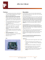
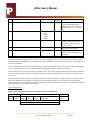
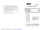
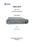
vWire User Manual
Version 1.7a August 18, 2009
iP Solutions Corporation • 41784 Higgins Way • Fremont, CA 94539 • Phone: (510) 651-6403
Rev 1.7a August 18, 2009
vWire User’s Manual
Features, 1
Description, 1
vWire DC Specifications Table, 2
vWire Top View Layout, 3
vWire Pin/Board Function Descriptions, 4
Power, 4
AUX Connector, 4
Table 1 Aux Pin Descriptions, 4
Reset Button, 4
Analog Inputs AD0 and AD1, 4
Table 2 Switch 1 Settings for Analog Input Range, 5
Analog Outputs DAC0/RSSI and DAC1, 5
Digital Inputs and Relay Outputs, 5
Inputs, 5
Relay outputs, 6
Table 3 Switch S2 Settings for Digital Inputs and Relay Outputs, 7
RS232 I/O, 7
Wireless Range, 8
Antenna, 8
Configuring vWire, 9
Opening vWireCfg.exe, 9
Loading a Configuration File, 10
Saving a Configuration File, 10
Changing Analog Input Parameters, 11
Changing Analog Output Parameters, 12
Table 4 Received Signal Level (RSSI), 12-13
Changing Digital I/O Parameters, 13
Changing Other Parameters, 14
My Adr, 14
Dest Adr, 14
Bound Adr, 14
Channel, 14
Retries, 14
Sample Rate, 14
Baud Rate, 14
Power Level, 14
Transmission, 14
UART I/O, 15
Reset, 15
Device Configuration, 15
Get Device Configuration, 15
iP Solutions Corporation • 41784 Higgins Way • Fremont, CA 94539 • Phone: (510) 651-6403
Rev 1.7a August 18, 2009
vWire User’s Manual
Program Device Configuration, 15
I/O Line Passing and Network API, 15
I/O Line Passing mode with Transparent RS232, 15
Table 5 Line Passing I/O Pairs, 16
Table 6 Overall Gain for Analog Input Range Selections, 16
Example 1, 16
I/O Line Passing mode with API, 18
Example 2, 18
Table 7 Basic Elements of 83h Response Packet, 19
Table 8 Active Channel, 19
Table 9 Digital Channel State, 19
Example 3, 19
Network API mode, 20
Command/Response Packet protocols, 20
Table 10 List of Commands, 20-22
Local Packet Protocols, 22
Table 11 Type 08h Local Command Packet, 22
Table 12 Type 09h Local Command Packet, 23
Table 13 Type 88h Local Response Packet, 23
Table 14 Type 83h Local Response Packet, 23
Table 15 Active Channel, 23
Table 16 Digital Channel State, 23
Table 17 Type 88h Packet Status Description, 24
Local Command/Response Packet Examples, 24
Remote Packet Protocols, 27
Table 18 Type 17h Remote Command Packet, 27
Table 19 Type 97h Remote Response Packet, 27
Table 20 Return Data [ n Bytes] Element, 27
Table 21 Active Channel, 27
Table 22 Digital Channel State, 27-28
Example 1: IS Command and Response, 28
Example 2: DB Command and Response, 29
Table 23 Special Characters, 30
Table 24 Type 97h Packet Status Description, 30
vWire Applications, 31
Application 1: Line Passing, 31
iP Solutions Corporation • 41784 Higgins Way • Fremont, CA 94539 • Phone: (510) 651-6403
Rev 1.7a August 18, 2009
vWire User’s Manual
Features
•
•
•
•
•
•
•
•
•
•
•
Description
vWire board-pairs provide wireless virtual cables up
to 1 mile in length for multiple analog and digital
signals in I/O Line Passing mode
Network API mode supports up to 65533 vWire
boards in a network that can monitor and control
hundreds of thousands of remote wireless nodes
2 analog inputs and 2 analog outputs; Input ranges:
0-20mA, 0-2.5V, 0-5V or 0-20V; Output levels 05V
6 opto-isolated digital inputs accept 0+/-30V input
levels; Input polarity can be switched between
active high and active low.
6 solid state relay outputs rated at 60VAC/DC at up
to 0.5A
100mW wireless output power. Line of sight
wireless range of up to 1 mile; 12 frequency
channels in the 2.4GHz band. Whip antenna
included
Transparent RS232 serial cable replacement mode
useful for Modbus, custom protocols or vWire data
packets
Screw terminal input/output connections
DIN Rail or panel mount
Low power 9-30 VDC power requirement; Polarity
neutral input; Polyfuse protected
Board size: 4” X 4”
vWire
The vWire board is a low power wireless data acquisition and
control board that operates in two major modes, I/O Line Passing
mode and Network API mode.
I/O Line Passing mode allows up to eleven wireless virtual cable
connections to be established between two or more vWire boards.
Analog or digital/switch signal inputs on one board are wirelessly
transmitted to another vWire board where they are reproduced as
identical analog or digital/switch signals. Additionally, an RS232
signal input on one board is received as an RS232 output signal
on the remote board allowing transparent RS232 virtual cable
operation.
Network API mode allows up to 65533 vWire boards to be
connected in a peer-to-peer network allowing remote analog and
digital data monitoring and control of hundreds of thousands of
nodes over the entire network. Up to 12 separate networks can be
established in the same area.
Analog and digital inputs on any vWire board in the network can
be retrieved through any other vWire board in the network.
Similarly, an analog or digital output can be forced on any vWire
board in the network through any other vWire board in the
network.
An easy to use configuration utility is provided to set up an
application in minutes. Default configuration files show both
Line passing and Network API setups.
Applications
•
•
•
•
•
Wireless switch extender for light control, motor control,
etc.
Add remote monitoring and control capability to an
existing PLC system without affecting or changing PLC
program
Wireless RS232 cable for Modbus or other protocols
Wireless monitoring of pressure, flow, temperature,
speed, alarms, chlorine, levels, moisture, etc.
Automate an entire factory using network API mode to
monitor/control data with up to 65533 boards in a
network
.
iP Solutions Corporation • 41784 Higgins Way • Fremont, CA 94539 • Phone: (510) 651-6403
Rev 1.7a August 18, 2009
Page 1
vWire User’s Manual
vWire DC Specifications T=25 degrees C
Parameter
Description
Minimum
Typical
9
Maximum
Units
30
Volts
Note
s
Vs
Min-Max supply voltage range
Isrx
Rx supply current 9/12/24V
30/25/15
45/37/22
mA
Istx
Tx supply current 9/12/24V
100/80/45
150/120/60
mA
Vin 1
Analog voltage input mode range 1
0
2.5
Volts
1
Vin 2
Analog voltage input mode range 2
0
5.0
Volts
1
Vin 3
Analog voltage input mode range 3
0
20.0
Volts
1
Zvin
Analog voltage input Z
AI
Analog current input mode
Zai
Analog current input mode Z
DacV
DAC voltage output range
0
VRelay
Relay contact voltage range
IRelay
100K
Ohms
mA
1,2
Ohms
2,4
5
Volts
1
0
60
Volts
AC/DC
Output current range
0
0.5
Ampere
| DICOM – Din |
Digital input common-voltage
range
0
30
Volts
Vt
Din channel threshold
1.4
4
Volts
Din
Din channel OFF/ON levels
DICOM +/- Vtmin
> (DICOM + Vtmax)
or
Volts
3
0
20
125
3
< (DICOM – Vtmax)
Idin
Digital input current
0
(|DICOM – Din| - 2) /
3.4
mA
3
Idin24
Digital input current |DICOM - Din|
= 24V
0
6.5
mA
3
Idin12
Digital input current |DICOM - Din|
= 12V
0
3
mA
3
Idin5
Digital input current |DICOM -Din|
= 5V
0
0.9
mA
3
Notes:
1.
2.
3.
4.
Basic measurement resolution is 10 bits. Vref is 2.5V. Input range is set with switch S1.
Limit input current to <= 20mA to prevent excess power dissipation in input termination resistor.
Limit absolute voltage difference between DICOM and Din to +/-30V
Vin to ADC will be Input current x 125 ohms. For I = 20mA and ADC channel gain set to 0 – 2.5V this gives full scale 10 bit value (1023).
iP Solutions Corporation • 41784 Higgins Way • Fremont, CA 94539 • Phone: (510) 651-6403
Rev 1.7a August 18, 2009
Page 2
vWire User’s Manual
vWire Connector, Pin and Switch Locations
Relay Enable Switch, S2
Relay Outputs J4
Digital Inputs J3
Power In 9-24V J1
Polyfuse
Analog Out J2
Reset Switch
Aux Connector, J5
Analog In J2
Analog Mode
Switch S1
U.FL Antenna Connector
RS232 Port
Din Rail Mount
iP Solutions Corporation • 41784 Higgins Way • Fremont, CA 94539 • Phone: (510) 651-6403
Rev 1.7a August 18, 2009
Page 3
vWire User’s Manual
vWire Pin/Board Functions
Refer to the physical layout above.
Power
An external power supply rated at 9 – 30V and 200 mA is required. Connect this supply to the vWire board at the J1 connector.
Polarity is not important.
AUX Connector
Table 1 AUX Pin Description
Pin
J5-1
J5-2
J5-3
J5-4
J5-5
J5-6
J5-7
J5-8
J5-9
J5-10
Description
Ground
3.3V
Sleep
RTSn
CTSn
nc
Dout (tx)
nc
Din (rx)
Resetn
Refer to Table 1 above.
Din, Dout, RTSn and CTSn UART pins are for factory use only.
The Sleep pin can be used to put the wireless module into hibernate or doze mode and reduce current consumption. The Sleep
pin configuration will need to be enabled before this pin can be used. Once enabled, this pin must be pulled down to keep the
wireless module on. Taking the Sleep pin high will then put the module into sleep mode. This reduces the wireless module
current consumption to about 10uA for hibernate configuration and about 50uA for Doze configuration. However, other
components on the vWire will continue to draw a current of 5-10mA. Contact the factory for configuration details.
The Resetn pin will reset the vWire board when pulled low momentarily. This pin will be driven low when the on-board reset
button is pressed.
Reset Button
Momentary switch, S3, will reset the board when pressed. This switch is labeled RST.
Analog Inputs AD0 and AD1
Each vWire board has two analog ADC inputs with 10 bits of resolution, AD0 and AD1, available on connector J2. Each analog
input can be configured as active or disabled. Switch S1 is used to set different input voltage ranges of 0-2.5V, 0-5V or 0-20V.
Alternatively the input can be set for a 0-20mA current input. See the Table 2 below for settings.
iP Solutions Corporation • 41784 Higgins Way • Fremont, CA 94539 • Phone: (510) 651-6403
Rev 1.7a August 18, 2009
Page 4
vWire User’s Manual
Use the vWireCfg.exe utility to activate or disable the states of the analog inputs in conjunction with setting the S1 switch
manually. The vWireCfg.exe utility will indicate the proper settings for switch S1 as different states are selected although the
switch still has to be set manually. See the Configuring vWire section for more details.
Table 2 Switch 1 Settings for Analog Input Range
AD0 set Switch S1
AD1 set Switch S1 0 - 2.5 V
0 - 5.0 V
0 - 20.0 V
0 – 20 mA
Pos 1
Pos 4
OFF
ON
OFF
OFF
Pos 2
Pos 5
OFF
OFF
ON
OFF
Pos 3
Pos 6
OFF
OFF
OFF
ON
Analog Outputs DAC0 /RSSI and DAC1
Two analog outputs with 12 bits resolution, DAC0 and DAC1, are available on connector J2. Each output has an output range of
0 - 5V. DAC0 can optionally be configured as an RSSI signal strength output. If not used, the analog outputs can be disabled.
There is a 0 – 25 second count down timer used for both DAC0 and DAC1 in Line Passing mode. If this timer reaches zero
before a valid signal is received from a remote vWire then the DAC0 and DAC1 output will be set to zero. If a valid signal is
received during this count down interval then the timer resets itself and starts over. Setting the delay to 0 seconds will turn off
this timer so that the outputs will not be reset to zero. The output will thus retain the last update that it received forever. There is
a count down timer for the RSSI mode as well.
Use the vWireCfg.exe utility to configure the active states of the analog outputs. See the Configuring vWire section for more
details.
Digital Inputs and Relay Outputs
Digital inputs and relay outputs share 6 I/O channels from the microprocessor so each channel needs to be configured to be an
input or a relay output. A vWire board may use all six channels for digital inputs in which case there are no relay outputs
available. Conversely, a vWire board may use all six channels for relay outputs in which case no digital inputs are available.
Normally there will be a mix of inputs and relay outputs used on a given board but the key thing to remember is that there are a
total of 6 digital I/O channels available.
Inputs
Six general-purpose optically isolated input pins, DI0-DI5 are available on connector J3. All I/O channels configured as an
input should have the corresponding position on switch S2 set to the OFF state. See the Table 3 below for S2 settings.
The DICOM input pin on J3 is used to set the input polarity for all DI inputs. Typically, DICOM will be connected to 0V, 12V
or 24V but could also be set to a negative voltage. For example, if DICOM = 12V (or 24V), then the digital input channel will
be turned ON when DI = 0V and OFF when DI = 12V (or 24V). To invert the polarity, set DICOM = 0V, then the input channel
will be OFF for DI = 0V and ON for DI > 5V. For most cases it is best to drive the DI inputs with a relay contact, open
collector/drain or a switch that goes between two distinct levels.
The utility, vWireCfg.exe, is used to enable the use of digital inputs on a given channel. This utility also indicates the correct
settings for switch S2 for a given choice of digital inputs and relay outputs. Set the S2 switch manually to match the
indicated settings. See the Configuring vWire section for more details.
iP Solutions Corporation • 41784 Higgins Way • Fremont, CA 94539 • Phone: (510) 651-6403
Rev 1.7a August 18, 2009
Page 5
vWire User’s Manual
Relay Outputs
Six MOSFET, 60VAC-DC/0.5A relay outputs are available on connector J4 as K1-K6.
Relay K1 has both terminals, K1a and K1b, brought out to connector pins and is optically isolated from the other relays and
internal circuitry. K2-K6 each have one relay terminal connected to a common output connector pin, COMK2_K6, while the
other pins are brought out to individual output connector pins. Each of these relays is optically isolated from all internal board
circuitry.
If an I/O channel pin is to be used as a relay output, then the corresponding S2 switch position should be manually set to the ON
state as indicated in the Table 3 below.
The default condition for an output relay can be set to normally ON (closed) or normally OFF (open). If a relay is set to the
normally ON condition keep in mind that the solid state relay does not work like a mechanical electromagnetic relay works, i.e.,
when the board power is off the contacts will be open.
There is a 0 – 25 second count down delay timer associated with each active relay output in Line Passing mode. If this timer
counts down to zero before an update signal is received from a remote vWire then the output channel will be set to will be set to
its default state of ON or OFF. If a signal is received during this count down interval then the timer resets itself and starts over.
Setting the delay to 0 seconds will turn off this delay counter so that the output will not be reset. The output will thus retain the
last update that it received forever.
The utility, vWireCfg.exe, is used to enable the use of relay outputs on a given channel. This utility also indicates the correct
settings for switch S2 for a given choice of digital inputs and relay outputs. Set the S2 switch manually to match the
indicated settings. Table 3 also shows the correct S2 settings for a given configuration. See the Configuring vWire section for
more details.
iP Solutions Corporation • 41784 Higgins Way • Fremont, CA 94539 • Phone: (510) 651-6403
Rev 1.7a August 18, 2009
Page 6
vWire User’s Manual
Table 3 Switch S2 Settings for Digital Inputs and Relay Outputs
Set Switch S2 Chnl-2 DI-0
Chnl-2 K1
Chnl-2 DISABLE
Chnl-3 DI-1
Chnl-3 K2
Chnl-3 DISABLE
Chnl-4 DI-2
Chnl-4 K3
Chnl-4 DISABLE
Chnl-5 DI-3
Chnl-5 K4
Chnl-5 DISABLE
Chnl-6 DI-4
Chnl-6 K5
Chnl-6 DISABLE
Chnl-7 DI-5
Chnl-7 K6
Chnl-7 DISABLE
Pos 1
OFF
ON
X
Pos 2
Pos 3
Pos 4
Pos 5
Pos 6
OFF
ON
X
OFF
ON
X
OFF
ON
X
OFF
ON
X
OFF
ON
X
RS-232 I/O
An RS232 connector, P1, is available for communication with a host system.
In Line Passing Transparent mode, an input to the RS232 port is seen as an output on a remote vWire board and an RS232 input
on the remote vWire board is seen as an output on the local vWire RS232 port, i.e., a virtual RS232 cable is formed.
In 16-bit Network API mode, data and command packets can be sent to the local vWire board or wirelessly to other vWire
boards. Up to 65533 vWire boards can be addressed using a 16-bit destination value. Up to 12 separate networks of this size can
operate in the same region.
The RS232 port is used to set or change the configuration of the vWire board using the vWireCfg.exe utility. This utility allows
the baud rate to be changed from its default 115200 baud to other standard baud rates. The host must match this baud rate to
communicate with the vWire RS232 port. The host RS232 COM port should always be set to 8 bits, no parity, 1 stop bit and no
handshake.
iP Solutions Corporation • 41784 Higgins Way • Fremont, CA 94539 • Phone: (510) 651-6403
Rev 1.7a August 18, 2009
Page 7
vWire User’s Manual
Wireless Range
A clear line-of-sight range of up to 1 mile is possible under the right conditions. Indoors, the range will be significantly reduced
and may be 300 feet or less depending on walls and other obstacles. The included whip antenna should be mounted external to
any metal case and should have a clear line of sight to remote vWire locations if possible.
Configuration options allow for selecting five different transmitter power levels to fit the application. The power level should
generally be set to the lowest possible level that still allows reliable communication between the two sites. This will reduce
interference possibilities with neighboring wireless installations. Power level defaults to the highest level of 18dbm. Always
check that proper signal strength can be obtained between two sites before doing a permanent installation.
Antenna
Every vWire board comes with a small antenna. This is either a pre-attached wire antenna or an external whip antenna. The
external whip antenna attaches to the vWire board through its coaxial cable to a U.FL connector on the wireless module. See
page 3 above for a vWire board, which shows the location for this connector. This connector is very small and care should be
exercised when plugging or unplugging the antenna cable into this connector. Make sure that the wireless unit is still seated
properly into its socket after connecting the antenna. Other adaptors are available from various manufacturers to mate the U. FL
connector to other connector types.
The base of the antenna may be mounted to a metal sheet or plate but there should be no other metal object near the antenna
body. If the antenna base is mounted to a metal base then the metal should be grounded.
iP Solutions Corporation • 41784 Higgins Way • Fremont, CA 94539 • Phone: (510) 651-6403
Rev 1.7a August 18, 2009
Page 8
vWire User’s Manual
Configuring vWire
The settings for the various modes of operation and other board parameters can be done through use of a utility program,
vWireCfg.exe. Some of the vWire board settings are done with manual switches, specifically, enabling relays with switch S2 and
setting analog input mode/gain with switch S1. This program interfaces to a vWire board through an RS232 host COM
connection and should be installed as part of the initial vWire setup. For those PC computers that no longer have an RS232
COM port, a USB to RS232 COM port adaptor is included in the vWire Development Kit. See the Getting Started document for
details on how to install the vWireCfg.exe program and using the RS232 port.
Opening vWireCfg.exe
Open vWireCfg.exe by double clicking on its desktop icon.
The screen shot below in Figure 1 is similar to what you should see on your screen once vWireCfg.exe has been opened.
Buttons on the main form are grouped into Analog Input Parameters, Analog Output Parameters, Digital I/O Parameters,
Other Parameters and Device Configuration. Help is available to explain operation of each button. Under the Help menu,
select the Tool Tip Help item. Now when the mouse cursor is positioned over a button (most buttons) a help description will pop
up for that button.
Figure 1
iP Solutions Corporation • 41784 Higgins Way • Fremont, CA 94539 • Phone: (510) 651-6403
Rev 1.7a August 18, 2009
Page 9
vWire User’s Manual
Loading a Configuration File
Under the File menu, select Load_Config_File_To_Form and an Open dialog window pops up as shown in Figure 2. Several
files are shown one of which can now be selected to set default configurations for the vWire board. Instead of using the File
menu to open this dialog window, it can be displayed by holding down the control key and hitting the L key (ctl-L) at the same
time.
Figure 2
Select default_line_passing_base.cfg and click OK. All the configuration settings in the default_line_passing_base.cfg file have
now been loaded to the form on the screen but not written to the vWire board.
Saving a Configuration File
Under the File menu, select Save_Form_To_Config_File and a Save As dialog window pops up as shown in Figure 3. Select or
type a file name into the File name box. Now click on the Save button to save the configuration information shown on the
screen to a file. Figure 3 shows a file name called Practice ready to be saved to the disk. Instead of using the File menu, the
Save As dialog window can be displayed by holding down the control key and hitting the S key (ctl-S) at the same time.
iP Solutions Corporation • 41784 Higgins Way • Fremont, CA 94539 • Phone: (510) 651-6403
Rev 1.7a August 18, 2009
Page 10
vWire User’s Manual
Figure 3
Saving a configuration file does not mean that a vWire connected to the PC has been updated with that configuration. That is a
separate process discussed under Device Configuration below.
Changing Analog Input Parameters
There are ten input/output I/O channels on the vWire board and Chnl-0 and Chnl-1 are dedicated respectively to analog inputs
AD0 and AD1. Under the Analog Input Parameters group (see figure 1), click on the darker gray Chnl-0 button below the
column Mode to change the mode to DISABLE and click again to change it back to AIN. Click on the Chnl-0 dark gray button
under the Range column to change the input range. Click repeatedly to go through all choices. Notice that when a different
range setting is selected that the settings for S1 will change. S1 is a physical switch on the vWire board so the S1 settings
indicated here must be set manually when a particular configuration has been chosen. If a channel is disabled, some of the
selections will go to a lighter gray indicating that they are not important or are not used for this selection. In general, a dark gray
shading means a button or value is active while a light gray shading indicates an inactive button or a don’t care value.
For practice, select Chnl-0 as active AIN mode and gain as 0-20V. Also select Chnl-1 as inactive by setting mode to DISABLE.
Here is what should now be displayed as shown in Figure 4.
iP Solutions Corporation • 41784 Higgins Way • Fremont, CA 94539 • Phone: (510) 651-6403
Rev 1.7a August 18, 2009
Page 11
vWire User’s Manual
Figure 4
Changing Analog Output Parameters
I/O channels 8 and 9 are dedicated respectively to analog outputs, DAC0/RSSI and DAC1. Refer to the Analog Output
Parameters box on the main screen for controls related to these settings.
Channel 8 can be configured to be a DAC0 or RSSI output or put into a DISABLE state by clicking the button under the Mode
column and channel 8 row. If enabled, the DAC0/RSSI output is available on the J2 connector. This output has a fixed range of
0-5 volts. This output is set to a value either by a remote vWire AD0 analog input in Line Passing mode or by a host system
sending an API packet via Network API mode. See the I/O Line Passing and Network API section for details.
If channel 8 is used as an RSSI output, the output represents the wireless signal level last received from a remote vWire. A level
of 0V means that the output is inactive. A level from 0.05V to 1.20V indicates that the received level is below the rated
sensitivity of the wireless receiver and is not adequate for solid communications. A level greater than 1.20V up to 5 volts shows
the received level above the rated sensitivity of the receiver. Normally one would like to see levels above 2.90v for good signal
margin. Refer to Table 4 below.
Table 4 Received Signal Level (RSSI)
Received Signal Level (RSSI)
0V
0.35V
Notes
Inactive
-10db below rated receiver sensitivity. Basically, no signal.
iP Solutions Corporation • 41784 Higgins Way • Fremont, CA 94539 • Phone: (510) 651-6403
Rev 1.7a August 18, 2009
Page 12
vWire User’s Manual
Received Signal Level (RSSI)
1.2V
2.05V
2.90V
3.75V
4.60V
Notes
0 db Signal at rated receiver sensitivity. Unsatisfactory signal.
10db Signal is above rated receiver sensitivity but marginal.
Signal may fade out with environmental variations.
20db Signal is above rated receiver sensitivity and is a good
signal. Gives some fade margin for environmental variations.
30db Signal is above rated receiver sensitivity and is an
excellent signal. Gives large fade margin for environmental
variations.
40db Signal is above rated receiver sensitivity and is an great
signal. Gives very large fade margin for environmental
variations.
Channel 9 can be configured to be a DAC1 output or put into a DISABLE state. . If enabled, the DAC1 output is available on the
J2 connector. This output has a fixed range of 0 - 5 volts. DAC1 is set to a given level either by a remote vWire AD1 input in
Line Passing mode or by a host system sending an API packet via Network API mode.
The PWM delay number is the delay in seconds for a count down timer and is used by both DAC0 and DAC1 in Line Passing
mode. If this timer reaches zero before an update signal is received from the remote vWire then the DAC0 output will be set to
zero. If a signal is received during this count down interval then the timer resets to the number of seconds shown and starts over.
Setting the delay to 0 seconds will turn off this delay counter so that the output will not be reset to zero. The output will thus
retain the last update that it received forever.
If channel 8 is set to be an RSSI output, then it uses the RSSI delay count value of 0 to 25 seconds in Line Passing mode and
operates in a similar manner to the PWM delay counter.
In API Networking mode, each board in the network can have its DAC0 and DAC1 outputs programmed to any level between 0
and 5 volts using an API command packet. See the I/O Line Passing and Network API section for more details.
Changing Digital I/O Parameters
I/O channels 2 through 7 can be selected respectively as digital inputs DI0-DI5 or relay outputs K1- K6 and can be mixed in any
combination. For example one might select this combination: DI0, K2, K3, K4, DISABLE, DIO5.
Click the button in the channel 2 row under the Direction column. The label will change from INPUT to OUTPUT and then to
DISABLE as this button is repeatedly clicked. Select OUTPUT again. The label under the Pin column changes from DI0 to K1.
Notice also that the setting for switch S2 position 1 changed to ON. S2 switch settings must be set manually on the board to
match those indicated for a given configuration. In addition, when OUTPUT is selected, the previously grayed out button
under the Def State column will change to a darker gray and indicate OFF. The OFF state means that the relay will be normally
open. Click on this button to change it to ON. The Delay-sec button label has also changed from light gray to a darker gray
meaning that it is now active or enabled.
The Delay-sec delay number is the delay in seconds for a count down timer and is used by an Output channel in Line Passing
mode. If this timer reaches zero before an update signal is received from a remote vWire then the output will be set to its default
state, ON or OFF. If a signal is received during this count down interval then the timer resets to the number of seconds shown
and starts over. Setting the delay to 0 seconds will turn off this delay counter so that the output will not be reset to its default
state. The output will thus retain the last update that it received forever. This allows relays to go to a safe state when
communication is lost for some reason.
iP Solutions Corporation • 41784 Higgins Way • Fremont, CA 94539 • Phone: (510) 651-6403
Rev 1.7a August 18, 2009
Page 13
vWire User’s Manual
Changing Other Parameters
Other miscellaneous wireless module parameters can be configured using this group of controls.
My Adr
The My Adr up/down window value is the 16-bit address for a given vWire board. This address should be unique for each vWire
board in a given area or network. The default is 5000 (1388 hex). Values can be scrolled up or down through the range of 1 to
65534. Values can also be directly entered into this window.
Dest Adr
The Dest Adr up/down window value is a 16-bit address that points to another vWire board in line passing mode. The default is
5001 (1389 hex). Values can be scrolled up or down through the range 1 to 65534. Values can also be directly entered into this
window.
Bound Adr
The Bound Adr up/down window value is a 16-bit address that is used in Line Passing mode to bind the inputs of a vWire board
to the output of another board. The default is 5001 (1389 hex). Values can be scrolled up or down through the range 0 to 65535.
Values can also be directly entered into this window. If the value is set to 65535 (FFFFh), the board will accept output values
from any board in Line Passing mode. In API Network mode, the Bound Adr should be set to 0.
Channel
The Channel up/down window value is the wireless channel used and has a range of 12 to 23. All boards used in Line Passing
mode or all boards used in an API Network mode should have the same channel number. Channels can be selected to reduce
interference with other services in the area. The channel setting defaults to 12.
Retries
The Retries up/down window value controls the number of transmissions to try before declaring that a transmission has failed.
This value defaults to 2. Raising this number may help reliability in weak signal conditions but it also adds some latency to the
system.
Sample Rate
The Sample Rate up/down window value controls the rate at which the analog and digital inputs are scanned in msec. This value
has a range of 0 to 65535 (0 to FFFFh) msec. This value should be large enough to allow ample time for all channels to be
scanned, transmitted and received in Line Passing mode. This value defaults to 100 msec. In API Network mode, this value
should be set to 0.
Baud Rate
The Baud Rate button will step through all the available wireless module baud rates as it is repeatedly clicked. The baud rates
are 1200, 2400, 4800, 9600, 19200, 38400, 57600 and 115200. This value defaults to 115200 baud.
Power Level
The Power Level button will step through all the available wireless module transmitter power levels as it is repeatedly clicked.
The power levels available are Lowest (10dbm), Low (12dbm), Medium (14dbm), High (16dbm) and Highest (18dbm). The
default setting is Highest (18dbm).
Transmission
The Transmission button has two modes that can be selected, Transparent and API-1. The default mode, Transparent, puts the
vWire into Line Passing mode. This allows inputs on one board to be automatically passed to complementary outputs on another linked
board (bound), acting as a virtual cable for each I/O. AD0 input would be passed to DAC0 output, for example, if both were configured
as such. DI0 would be passed to K1 in a similar fashion and so on.
iP Solutions Corporation • 41784 Higgins Way • Fremont, CA 94539 • Phone: (510) 651-6403
Rev 1.7a August 18, 2009
Page 14
vWire User’s Manual
The RS232 port on one vWire will also appear at the output RS232 port of a destination vWire. Thus, it implies a virtual wireless cable
between the two RS232 ports. The Uart I/O button should be in the No state for this virtual RS232 cable mode. The UART I/O selection
should be set to No (default) for transparent RS232 operation.
The API-1 mode is for using the vWire in a peer-peer type network where communication between boards is done with RS232 port
packet frames initiated from or sent to a host system connected to this port. To use the vWire in this mode, set the Sample Rate to 0,
the Bound Adr to 0 and Uart I/O to No. Set a unique My Adr address for each board. See the I/O Line Passing and Network API
section for details.
UART I/O
The UART I/O button has two values that can be selected, No and Yes. For Line Passing mode, if this button is selected to be
No, normal Line Passing occurs between inputs on one board and outputs on another board that are bound together with the
Bound Adr parameter. The RS232 ports between the two boards act as a virtual cable between them, i.e., what goes in one board
comes out the other board intact. If the button is selected to be Yes then Line Passing between inputs of one board and outputs
of another board still happen. In addition, the I/O data that has been received by a board will be passed to the RS232 port in the
form of an API-ID 83h packet type. This means that the virtual RS232 cable cannot work in this mode.
If the boards are working in Network API mode then this button should be selected to be No. See the I/O Line Passing and
Network API section for details and examples.
Reset Button
The Reset button resets the wireless module.
Device Configuration
Get Device Configuration
Clicking on the Get Device Configuration command button reads the vWire configuration information from the vWire connected
to the host RS232 COM port and updates the displayed form. If the board is configured in Line Passing mode and the UART I/O
button is set to Yes, then some trouble may be encountered with reading the device configuration if the remote board is sending
data frequently. One way to alleviate this problem is to shut the remote board off. If that is not possible, then usually a few tries
will suffice to read the device correctly.
Program Device Configuration
Clicking on the Program Device Configuration command button writes the displayed form information to the vWire connected
to the host RS232 COM port. If the board is configured in Line Passing mode and the UART I/O button is set to Yes, then some
trouble may be encountered with writing the device configuration if the remote board is sending data frequently. One way to
alleviate this problem is to shut the remote board off. If that is not possible, then usually a few tries will suffice to write the
device correctly.
I/O Line Passing and Network API
I/O Line Passing mode with Transparent RS232
This mode allows the inputs on one vWire board to be passed to the outputs of another vWire board. This is called a virtual
wired connection, hence the v in vWire. For example, if DI2 is enabled as a digital input on one board, then relay output K3
must be enabled on the other board to mirror this input. Any transition of state on the DI2 pin on the first board will now
transition the K3 relay on the other board.
Similarly for analog signals, AD0 on one board should be paired with DAC0 on another board and AD1 with DAC1. See Table
5 below for all the possible pairings between two boards operating in Line Passing mode. Remember that only 6 Digital Input/
Relay output pairs can be active between two boards.
iP Solutions Corporation • 41784 Higgins Way • Fremont, CA 94539 • Phone: (510) 651-6403
Rev 1.7a August 18, 2009
Page 15
vWire User’s Manual
Table 5 Line Passing I/O Pairs
I/O Channel
0/8
1/9
8/0
9/1
2
3
4
5
6
7
2
3
4
5
6
7
na
na
First board
AD0
AD1
DAC0
DAC1
DI0
DI1
DI2
DI3
DI4
DI5
K1
K2
K3
K4
K5
K6
RS232 RX
RS232 TX
Second Board
DAC0
DAC1
AD0
AD1
K1
K2
K3
K4
K5
K6
DI0
DI1
DI2
DI3
DI4
DI5
RS232 TX
RS232 RX
Keep in mind that there may be a translation of levels since the AD inputs can have different ranges while the DAC outputs have
a fixed 0 – 5V range. See Table 6 below for overall gain.
Table 6 Overall Gain for Analog Input Range Selections
Input Range/Mode
0 –2.5V
0 – 5.0V
0 – 20.0V
0 – 20.0mA
DAC Output range
0 – 5.0V
0 – 5.0V
0 – 5.0V
0 – 5.0V
Overall gain
2V/V
1V/V
0.25V/V
0.25V/mA
To enable Line Passing mode with transparent RS232 between two boards using the vWireCfg.exe program, the destination
address, Dest Adr, and the bound address, Bound Adr, of one board must contain the source address, My Adr that is set on the
other board. In addition the transmission mode must be set to Transparent and the Channel setting must be set to the same
channel on both boards. UART I/O should be set to No.
Example 1
Connect the host RS232 COM port to a vWire board RS232 port. Double click the vWireCfg.exe icon to run the configuration
program.
Load the configuration file default_line_passing_base.cfg and then click on the Program Device Configuration button.
The screen shot shown in Figure 5 should be similar to what is now displayed. Be sure to set switches S1 and S2 as shown.
iP Solutions Corporation • 41784 Higgins Way • Fremont, CA 94539 • Phone: (510) 651-6403
Rev 1.7a August 18, 2009
Page 16
vWire User’s Manual
Figure 5
Now disconnect the host from this first (base) vWire board and connect it to a second (remote) vWire board.
Load the configuration file default_line_passing_remote.cfg and then click on the Program Device Configuration button.
The screen shot shown in Figure 6 should be similar to what is now displayed. Be sure to set switches S1 and S2 as shown.
iP Solutions Corporation • 41784 Higgins Way • Fremont, CA 94539 • Phone: (510) 651-6403
Rev 1.7a August 18, 2009
Page 17
vWire User’s Manual
Figure 6
The two boards are now in Line Passing mode. Try putting an analog signal into AD0 of one board and observe the DAC0
output on the other board. The output should be the same value as the input (allowing for the +/- tolerances of the system).
I/O Line Passing mode with API
Example 2
Using the same setup as example 1, reconnect the host to the first (base) vWire board and click on the Get Device Configuration
button. Now click on the UART I/O button to change it to Yes. Click on the Program Device Configuration button to write the
new configuration to the board. The boards are still configured to be in Line Passing mode but with the UART API enabled on
the first board.
With these settings, the second board (remote) will scan its I/O input lines and transmit data every ½ second. The first board will
receive this transmission and pass the data to the appropriate complementary base board outputs. The data that arrives at the first
board is also sent out on the RS232 port as a packet. This is the form of the data packet (in hex) that is received at the host every
½ second. Examine this packet against the basic elements of a type 83h packet as shown below in Table 7. See Table 8 and
Table 9 for details.
7E 0 E 83 13 89 3F 0 1 6 FC 0 FC 0 1F 0 0 83
iP Solutions Corporation • 41784 Higgins Way • Fremont, CA 94539 • Phone: (510) 651-6403
Rev 1.7a August 18, 2009
Page 18
vWire User’s Manual
Table 7 Basic Elements of 83h Response Packet
7Eh
Header
Len
1 Byte
2 Byte
83h
Src Adr
1 Byte
2 Bytes
Data
Active
Dig Chnl AD0
Chnl
State
1 Byte 1 Byte 1 Byte 2 Bytes [2 Bytes] [2 Bytes]
Length of Data Checksum = 255 – (sum of data bytes) RSSI
0
1
Tail
Ck
Sum
1 Byte
AD1
[2 Bytes]
Table 8 Active Channel: 1 indicates active, 0 indicates inactive, x indicates configuration dependent 1 or 0
Bit 7
Na
Bit 6
Na
Bit 5
Na
0
0
0
Bit 4
Na
Bit 3
Na
0
0
MSB Byte
Bit 2
AD1
Bit 1
AD0
x
x
Active Channels
Bit 0
Bit 7 Bit 6
Na
DI5
DI4
or
or
K6
K5
0
x
x
Bit 5
DI3
or
K4
x
Bit 4 Bit 3
DI2
DI1
or
or
K3
K2
x
x
LSB Byte
Bit 2
DI0
or
K1
x
Bit 1
Na
Bit 0
Na
0
0
Table 9 Digital Channel State: 1 indicates a high level *, 0 indicates a low level *, x indicates application dependent 1 or 0
Bit 7
Na
Bit 6
Na
Bit 5
Na
0
0
0
Bit 4
Na
Bit 3
Na
0
0
MSB Byte
Bit 2
Na
Bit 1
Na
0
0
Digital Channel State
Bit 0
Bit 7 Bit 6
Na
DI5
DI4
or
or
K6
K5
0
x
x
Bit 5
DI3
or
K4
x
Bit 4 Bit 3
DI2
DI1
or
or
K3
K2
x
x
LSB Byte
Bit 2
DI0
or
K1
x
Bit 1
Na
Bit 0
Na
0
0
* For an output relay, a 1 is relay OPEN and a 0 is relay CLOSED.
For two-byte values Len, Src Adr, AD0 and AD1 the data is sent MSB first and then LSB. Also, bytes with brackets [ ] around
them are optional and depend on what channels are enabled. If no digital channels DI or K are enabled then the Dig Chnl bytes
will not appear in the response. Similarly if the AD0 channel is not enabled then these bytes will not appear in the response.
Same thing applies for AD1.
Use the two-byte Active Channel information to determine what byte information will be in the rest of the packet.
Example 3:
Here is a response with only AD0 enabled:
7E 0 A 83 13 89 3D 0 1 2 0 0 1F 81
iP Solutions Corporation • 41784 Higgins Way • Fremont, CA 94539 • Phone: (510) 651-6403
Rev 1.7a August 18, 2009
Page 19
vWire User’s Manual
The Active Chnl bytes are MSB = 2, LSB = 0 indicating that AD0 is the only active channel. Therefore the Dig Chnl State bytes
will not be present and the AD1 channel byte will not be present. Only the AD0 byte data MSB = 0, LSB = F follow the Active
Chnl bytes. Of course the check sum byte, Ck Sum, is always there.
Notice that the RSSI data 3Dh (61 decimal) is always available. The receiver sensitivity for the Xbee Pro wireless module is
published to be –100dbm therefore margin can be calculated as (received signal strength) - (receiver sensitivity) = –61 – (–100) =
39db which is excellent.
The Src Adr or source address is 1389 hex or 5001 decimal. That, of course, is just what was programmed into the second
(remote) vWire board.
Network API mode
This mode allows a general-purpose network of up to 65,533 boards to be established using a unique 16-bit My Adr address, for
each board in the network. This network is a peer-to-peer type network where any one board can communicate directly with any
other board in the network using a packet protocol. Multiple independent networks in the same area can also be established by
using different channels (channel 12 through channel 23) for each different network.
To enable the API Network mode using the vWireCfg.exe program, set the transmission mode to API-1, UART I/O to OFF,
Sample Rate to 0 and Bound Adr to 0 on all boards. Additionally set all boards in a network to the same channel. Set each board
in the network to a unique 16-bit My Adr address. My Adr address range is from 1 to 65534. The Dest Adr address does not
matter, as this will be embedded into the transmitted command packet.
This peer-peer network is often used in a single-boss, many-workers arrangement where one and only one of the boards, the
boss, always initiates any communication with the workers in the network. A host controller is connected to the boss vWire
board and it sends command packets or receives response packets through this board’s RS232 port. The boss will address the
local vWire board or a remote worker vWire board individually using the appropriate local or remote command packet type
using the destination address set to the worker vWire board My Adr address.
If operating in a multi-boss peer-to-peer arrangement then each board can act as a boss or worker and therefore each board will
require its own host processor. Each host is then responsible for setting the desired destination address in a command packet that
it sends.
The command packet allows looking at the input and output I/O data to or from a vWire board. It also allows other parameter
values to be set or read remotely. This is useful, for example, to look at the RSSI signal strength data or to set power levels on a
particular worker board.
Command/Response Packet Protocols
Local or remote command packets, are used to send two-character ASCII commands to a given vWire wireless module. There
are many different AT commands available to set or query module parameters. See Table 10 below for some of these
commands.
Table 10 List of Commands
Cmd
IS
Description
Force a read of all enabled inputs
Parameter(s)
-
Default
Value
-
Notes
First returns a status response
packet and then returns a data
response packet which includes
input/output state and input values.
Returns error if no DI or AD
iP Solutions Corporation • 41784 Higgins Way • Fremont, CA 94539 • Phone: (510) 651-6403
Rev 1.7a August 18, 2009
Page 20
vWire User’s Manual
Cmd
Description
Parameter(s)
Default
Value
M0
Set DAC0 value
0 - 03FFh
-
M1
Set DAC1 value
0 - 03FFh
-
IO
Set digital outputs
8 bit value
K1 04h
K2 08h
K3 10h
K4 20h
K5 40h
K6 80h
D2
Set/read DI0/K1 State
D3
Set/read DI1/K2 State
D4
Set/read DI2/K3 State
D5
Set/read DI3/K4 State
D6
Set/read DI4/K5 State
D7
Set/read DI5/K6 State
DB
Read received signal strength
0 = Disable
3 = DI0
4 = K1 Closed or On
5 = K1 Open or Off
0 = Disable
3 = DI1
4 = K2 Closed or On
5 = K2 Open or Off
0 = Disable
3 = DI2
4 = K3 Closed or On
5 = K3 Open or Off
0 = Disable
3 = DI3
4 = K4 Closed or On
5 = K4 Open or Off
0 = Disable
3 = DI4
4 = K5 Closed or On
5 = K5 Open or Off
0 = Disable
3 = DI5
4 = K6 Closed or On
5 = K6 Open or Off
-
-
EC
Set/read number of CCA failures. If the
channel energy is too high (noise or another
wireless module transmitting) then the
packet is not transmitted and a CCA counter
is incremented.
Set /read CCA threshold
Set/read number of ACK failures
0 – FFFFh
-
0 – 50h
0 – FFFFh
2C hex
-
CA
EA
-
-
-
-
-
-
Notes
channels is enabled.
0000h = 0V
03FFh = 5V
0000h = 0V
03FFh= 5V
Setting a bit position to 0 in the 8
bit value turns on the output relay
associated with that bit position.
Setting a bit position to 1 will turn
off that relay. Example: IO 5F
(binary 0101 1111) will turn relay
K4 and K6 On and turn all other
relays Off.
If D2 = 3, set switch S2 position 1
to OFF.
If D2 = 4 or 5, set switch S2
position 1 to ON.
If D3 = 3, set switch S2 position 2
to OFF.
If D3 = 4 or 5, set switch S2
position 2 to ON.
If D4 = 3, set switch S2 position 3
to OFF.
If D4 = 4 or 5, set switch S2
position 3 to ON.
If D5 = 3, set switch S2 position 4
to OFF.
If D5 = 4 or 5, set switch S2
position 4 to ON.
If D6 = 3, set switch S2 position 5
to OFF.
If D6 = 4 or 5, set switch S2
position 5 to ON.
If D7 = 3, set switch S2 position 6
to OFF.
If D7 = 4 or 5, set switch S2
position 6 to ON.
Returns absolute value in –dbm of
last received signal
Must set to 0 after counter
saturates at FFFFh. The CCA
threshold defaults to –44dbm but
can be changed by using the CA
command.
Default is -44dbm
Must set to 0 after counter
saturates at FFFFh
iP Solutions Corporation • 41784 Higgins Way • Fremont, CA 94539 • Phone: (510) 651-6403
Rev 1.7a August 18, 2009
Page 21
vWire User’s Manual
Cmd
Description
Parameter(s)
Default
Value
0
ED
Scan all channels for RF energy
n = 0 to 6
PL
Set/read power level
4
WR
Write all changed parameters to flash
0 = 10 dbm
1 = 12 bm
2 = 14 dbm
3 = 16 dbm
4 = 18 dbm
-
AC
Apply command parameters
-
-
RR
Set/read number of retries
0–6
2
FR
Software reset wireless module
-
-
-
Notes
Local module command only.
Returns all channel RF signal
strength values. Time to scan all
channels is Time = (2n x 15.36)(12)
msec
18dbm is 63milliwatt
Unless this operation is done after
changing a parameter, the changes
will go away if the vWire loses
power or is reset.
Applies commands that are in a
queue waiting to be applied.
Maximum number of XBee retries
(802.14.4 can do 3 retries for every
one of these)
Takes about 100msec
Generally a command intended to set the contents of registers in the module will have one or more parameter data bytes that
immediately follow the command. For example, the PL power command uses a parameter value from 0 to 4 to set various power
levels of the transmitter.
After a command with parameters is sent to the RS232 port, the target destination module will reply with a packet indicating the
status of the command received. If the status is OK then the appropriate registers will have been updated.
Many commands may also be used to read back parameter values. For example, the PL command when sent with no parameters
will elicit a response packet from the target module, which returns the status and the contents of the power level register if the
status is OK.
Other commands do not have parameters and simply initiate an action on the module. The ED command is one such command.
This local command with no parameters will return 12 values indicating the energy or noise levels for each of 12 different
frequency channels. This command also accepts a parameter but still returns 12 parameters as before. The parameter in this case
simply adjusts the scan time used for each channel.
Local Packet Protocols
Table 11 Type 08h Local Command Packet (applies parameters immediately)
Header
7Eh
Length
1 Byte 2 Byte
Type
1 Byte
Frame#
1 Byte
Data
AT Cmd Optional Parameter Values
2 Bytes
0 to n Bytes
Tail
Ck Sum
1 Byte
Length of Data Checksum = 255 – (sum data bytes) iP Solutions Corporation • 41784 Higgins Way • Fremont, CA 94539 • Phone: (510) 651-6403
Rev 1.7a August 18, 2009
Page 22
vWire User’s Manual
Table 12 Type 09h Local Command Packet (queues parameters)
Header
7Eh
Length
1 Byte 2 Byte
Type
1 Byte
Data
AT Cmd Optional Parameter Values
2 Bytes
0 to n Bytes
Frame#
1 Byte
Tail
Ck Sum
1 Byte
Length of Data Checksum = 255 – (sum data bytes) Table 13 Type 88h Local Response Packet that may be received after a Local Command Packet
Header
7Eh
Length
1 Byte 2 Bytes
88h
1 Byte
Data
AT Cmd Status
Return Values
2 Bytes
1 Byte
0 to n Bytes
Length of Data Check sum = 255 – (sum data bytes) Frame#
1 Byte
Tail
Ck sum
1 Byte
Table 14 Type 83h Local Response Packet that may be received after a Local IS Command Packet
7Eh
Header
Len
1 Byte
Data
2 Byte
83h
Src Adr
1 Byte
2 Bytes
RSSI
0
1
Active
Dig Chnl
Chnl
State
1 Byte 1 Byte 1 Byte 2 Bytes [2 Bytes]
Length of Data Checksum = 255 – (sum data bytes) Tail
Ck sum
1 Byte
AD0
AD1
[2 Bytes]
[2 Bytes]
Table 15 Active Channel: 1 indicates active, 0 indicates inactive, x indicates configuration dependent 1 or 0
Bit 7
Na
Bit 6
Na
Bit 5
Na
0
0
0
Bit 4
Na
Bit 3
Na
0
0
MSB Byte
Bit 2
AD1
Bit 1
AD0
x
x
Active Channels
Bit 0
Bit 7 Bit 6
Na
DI5
DI4
or
or
K6
K5
0
x
x
Bit 5
DI3
or
K4
x
Bit 4 Bit 3
DI2
DI1
or
or
K3
K2
x
x
LSB Byte
Bit 2
DI0
or
K1
x
Bit 1
Na
Bit 0
Na
0
0
Table 16 Digital Channel State: 1 indicates high level *, 0 indicates low level *, x indicates application dependent 1 or 0
Bit
7
Na
0
Digital Channel State
Bit 0
Bit 7 Bit 6
Bit 6
Bit 5
Bit 4
Bit 3
Bit 2
Bit 1
Na
Na
Na
Na
Na
Na
Na
0
0
0
0
0
0
0
MSB Byte
DI5
or
K6
x
DI4
or
K5
x
Bit 5
Bit 4
Bit 3
Bit 2
Bit 1
Bit 0
DI3
or
K4
x
DI2
DI1
or
or
K3
K2
x
x
LSB Byte
DI0
or
K1
x
Na
Na
0
0
iP Solutions Corporation • 41784 Higgins Way • Fremont, CA 94539 • Phone: (510) 651-6403
Rev 1.7a August 18, 2009
Page 23
vWire User’s Manual
Tables 14, 15 and 16 are the same tables as Table 7, 8 and 9 used in the Line Passing section and are repeated here for
convenience.
Local vWire board packet commands with parameters will be immediately applied upon reception by a vWire wireless module if
the packet Type byte is set to a value of 08h. Setting the packet Type byte to 09h means that the command will be queued and
not immediately applied until an AC (apply changes) command is issued. As many commands with parameters may be issued as
desired before issuing an AC command. Also, any changes made by a command will not be permanently saved to flash unless
the WR command is issued. The WR command should be the last command issued.
Every local command packet sent out to a vWire wireless module will elicit a response packet. If a response packet is of type
88h then it includes a status byte with the meaning shown in Table 17 below.
Table 17 Packet Type 88h Status Description
Packet Type 88h Status
Description
0
OK
1
Error
2
Invalid command
3
Invalid parameter
Local Command/Response Packet Examples
Here is an example of an IS command that tells the local vWire wireless module to return a scan of all input and output data on
the module.
Connect the host RS232 cable to the first (boss) board. Load the configuration file, default_api_boss_5000.cfg. Disable all
analog and digital channels and then click on the Program Device Configuration button. The screen shot shown in Figure 7
should be similar to what is now displayed. Be sure to set switches S1 and S2 as shown:
iP Solutions Corporation • 41784 Higgins Way • Fremont, CA 94539 • Phone: (510) 651-6403
Rev 1.7a August 18, 2009
Page 24
vWire User’s Manual
Figure 7
All packet bytes for both commands and responses are shown as hex numbers.
Now if the host issues the following RS232 command string to the vWire board as shown here:
Type 08h command packet, IS command to scan all I/Os
7E 0 4 8 52 49 53 9
The response packet returned to the host will look like this:
7E 0 5 88 52 49 53 1 88
Type 88h response packet, status = error since no I/Os enabled
Notice that the response returned an error. This is because there are no channels enabled.
Enable the analog AD0 channel and click on Program Device Configuration. If the host then reissues the IS command:
7E 0 4 8 52 49 53 9
Type 08h command packet, IS command to scan all I/Os
This is the response back to the host:
7E 0 5 88 52 49 53 0 89
7E 0 A 83 13 88 0 0 1 2 0 0 2 DC
Type 88h response packet, status = OK
Type 83h response packet, source address, active channels, AD0 data
Notice that the response to the command is now two response packets instead of one. One is a type 88h response packet and the
next one is a type 83h packet. The IS command is one of the few commands that returns two packets in this fashion. The first
type 88h packet returned is simply a status packet and the status is OK. The type 83h packet returns the AD0 data, which is 0h,
2h where the first byte is the MSB byte. So AD0 = 0002h.
iP Solutions Corporation • 41784 Higgins Way • Fremont, CA 94539 • Phone: (510) 651-6403
Rev 1.7a August 18, 2009
Page 25
vWire User’s Manual
Load the configuration file, default_api_boss_5000.cfg to the boss board and then click on the Program Device Configuration
button. See Figure 8 for the settings.
Figure 8
If the host then reissues the IS command:
7E 0 4 8 52 49 53 9
Type 08h command packet, IS command to scan all Ios
This is the response back to the host:
7E 0 5 88 52 49 53 0 89
Type 88h response packet, status = OK
7E 0 E 83 7D 33 88 0 0 1 6 FC 0 FC 0 5 0 3 DA Type 83h response packet, source address, active channels, digital
data, AD0 and AD1 data
The same two response packets are returned to the host as before, however there is a lot more data. See Tables 14, 15 and 16
above for details.
If the host issues the local ED command to scan all RF channels for energy:
7E 0 4 8 52 65 64 DC
Type 08h command packet, ED command to scan all RF channels for
energy
This is the response back to the host:
7E 0 7D 31 88 52 45 44 0 60 60 60 60 60 60 60 60 60 60 60 60 1C Type 88h response packet, Status =
OK, Energy data for 12 rf channels.
iP Solutions Corporation • 41784 Higgins Way • Fremont, CA 94539 • Phone: (510) 651-6403
Rev 1.7a August 18, 2009
Page 26
vWire User’s Manual
Notice that there is only one response packet to this command. This is the more normal response to a command. Twelve
channels of data are returned starting immediately after the status OK byte.
Remote Packet Protocols
Table 18 Type 17h Remote Command Packet (applies parameters immediately if Apply = 02h)
Header
7Eh
Length
1 Byte 2 Bytes
17h
1 Byte
Data
0 0 0 0 0 0 0 0 Dest Adr
Apply
AT Cmd
8 Bytes
2 Bytes
1 Byte 2 Bytes
Length of Data Checksum = 255 – (sum data bytes) Frame#
1 Byte
Parameters
[n Bytes]
Tail
Ck Sum
1 Byte
Table 19 Type 97h Remote Response Packet received after a Remote Command Packet
Header
7Eh
Length
1 Byte 2 Bytes
97h
1 Byte
Frame#
1 Byte
Data
Src-16
AT Cmd Status
2 Bytes
2 Bytes
1 Byte
Length of Data Checksum = 255 – (sum data bytes) Src-64
8 Bytes
Return Data
[n Bytes]
Tail
Ck Sum
1 Byte
The Type 97 Remote Response Packet has a Return Data [n Bytes] element. The [ ] brackets indicate that this element is
optional. The number of bytes returned here depends upon what command is issued. For example, if the IS command to scan
all I/O channels is given, the response for this element is like the local 83h packet response for the local type 08h packet IS
command, as shown here in Table 20. See Table 21 and Table 22 for details.
Table 20 Return Data [ n Bytes] Element
Num Samples
1 Byte
Return Data [n Bytes]
Dig Chnl State
[2 Bytes]
Active Chnl
2 Bytes
AD0
[2 Bytes]
AD1
[2 Bytes]
Table 21 Active Channel: 1 indicates active, 0 indicates inactive, x indicates configuration dependent 1 or 0
Bit 7
Na
Bit 6
Na
Bit 5
Na
0
0
0
Bit 4
Na
Bit 3
Na
0
0
MSB Byte
Bit 2
AD1
Bit 1
AD0
x
x
Active Channels
Bit 0
Bit 7 Bit 6
Na
DI5
DI4
or
or
K6
K5
0
x
x
Bit 5
DI3
or
K4
x
Bit 4 Bit 3
DI2
DI1
or
or
K3
K2
x
x
LSB Byte
Bit 2
DI0
or
K1
x
Bit 1
Na
Bit 0
Na
0
0
Table 22 Digital Channel State: 1 indicates high level *, 0 indicates low level *, x indicates application dependent 1 or 0
Bit
7
Na
Bit 6
Bit 5
Bit 4
Bit 3
Bit 2
Bit 1
Na
Na
Na
Na
Na
Na
Digital Channel State
Bit 0
Bit 7 Bit 6
Na
DI5
DI4
Bit 5
Bit 4
Bit 3
Bit 2
Bit 1
Bit 0
DI3
DI2
DI1
DI0
Na
Na
iP Solutions Corporation • 41784 Higgins Way • Fremont, CA 94539 • Phone: (510) 651-6403
Rev 1.7a August 18, 2009
Page 27
vWire User’s Manual
0
0
0
0
0
MSB Byte
0
0
0
or
K6
x
or
K5
x
or
K4
x
or
or
K3
K2
x
x
LSB Byte
or
K1
x
0
0
Example 1: IS Command and Response
Remote commands expect a remote vWire to be enabled so connect the host RS232 cable to a second vWire board (worker) and
load default_api_worker1_5001.cfg. Now click on Program Device Configuration. Move the host RS232 cable back to the boss
board. The boss board should still have default_api_boss_5000.cfg programmed into it. If not then load and program it now.
Figure 9 and Figure 10 show the configuration states that should now be active.
Figure 9 Boss Configuration
iP Solutions Corporation • 41784 Higgins Way • Fremont, CA 94539 • Phone: (510) 651-6403
Rev 1.7a August 18, 2009
Page 28
vWire User’s Manual
Figure 10 Worker 5001 Configuration
If the host issues the packet type 17h IS command:
7E 0 F 17 52 0 0 0 0 0 0 0 0 7D 33 89 2 49 53 5C
This is the type 97h IS response
7E 0 18 97 52 0 7D 33 A2 0 40 53 54 9D 7D 33 89 49 53 0 1 6 FC 0 FC 0 5 0 5 9C
Use tables 19, 20, 21 and 22 to decipher the response data.
6 FC is Active Chnl
0 FC is Dig Chnl State
0 5 0 5 AD0 and AD1 data
Example 2: DB Command and Response
Type 17h DB command
7E 0 F 17 52 0 0 0 0 0 0 0 0 7D 33 89 2 44 42 72
Type 97h DB command response
7E 0 10 97 52 0 7D 33 A2 0 40 53 54 9D 7D 33 89 44 42 0 53 68
Here the data is the RSSI value of last received transmission, which in this case is 53h or –83dbm.
iP Solutions Corporation • 41784 Higgins Way • Fremont, CA 94539 • Phone: (510) 651-6403
Rev 1.7a August 18, 2009
Page 29
vWire User’s Manual
Remote commands with parameters will be immediately applied upon reception by a vWire wireless module if the Apply byte is
set to a value of 02h. Setting the Apply byte to 0 means that the command will be queued and not applied until a command, AC
(apply command), is issued. As many commands with parameters may be issued as desired before issuing an AC command.
Any changes made by a command will not be saved to flash unless the WR command is issued. The WR command should
be the last command issued.
When sending a packet to the RS232 port, certain characters must be treated specially. This is necessary so that the start of each
packet can be uniquely identified and to prevent any UART control characters from being misinterpreted. Any special characters
after the start of the packet should place the escape character, 7Dh, in the data output stream followed by the actual data
character XOR’d with 20h. The check sum byte does not need this rule.
When receiving a packet, any escape character seen after the start of the packet should be decoded by removing the escape
character from the input data stream and XORing the following character with 20h. Table 23 below shows the special
characters. Notice that the above examples have some characters that are escaped with the 7Dh escape character.
Table 23 Special Characters
Special
Characters
7Eh
Description
Start of packet character
7Dh
Escape character
11h
Xon control character
13h
Xoff control character
Every remote command packet of Type 17h sent out to a vWire wireless module will elicit a response packet with a Status byte.
The meaning of this status byte is shown in Table 24 below.
Table 24 Type 97h Status Description
Packet Type 97h Status
Description
0
OK
1
Error
2
Invalid command
3
Invalid parameter
4
No response
iP Solutions Corporation • 41784 Higgins Way • Fremont, CA 94539 • Phone: (510) 651-6403
Rev 1.7a August 18, 2009
Page 30
vWire User’s Manual
vWire Applications
Application 1 Line Passing
Shown on the following page is a vWire Line Passing application using a PLC controller and a pair of vWire boards that
remotely control a well pump and monitor storage tank water level. The PLC sends control signals to the local vWire board
which in turn copies these signals to the remote vWire board via virtual wires to control the well pump motor, panel cooling fan
and an alarm light. The PLC receives a tank water level (pressure) signal, panel temperature, motor running signal, motor fault
signal and intrusion alarm signal from the locally connected vWire, which has received these signals from the remote vWire.
When the tank level drops below some level, the PLC issues a command to turn the well pump motor on and fill the tank. When
the tank level reaches the desired level, the motor is shut off. The motor running signal is fed back to the PLC to indicate that the
motor is actually running along with a fault signal to indicate that there is no motor overload fault. There is also an intrusion
alarm signal to indicate when someone has entered the premises or opened the panel door. In case of an intrusion, the PLC
might turn on the remote alarm light as well as local alarms and issue an auto-dialer alarm call. Panel temperature is also
returned to the PLC, which can then decide to turn on a cooling fan in the remote panel if the temperature has exceeded a safe
operating value.
Wireless link
PLC/Host
Controller
Local vWire
Remote vWire
24V
GND
DICOM
D0
D1
D2
D3
D4
D5
K1a
K1b
K2a
K2b
K3a
K3b
COM
D0
D1
D2
D3
D4
D5
K1a
K1b
K2
K3
K4
K5
K6
COMK2_K6
GND
DICOM
D0
D1
D2
D3
D4
D5
DAC0
DAC1
AD0
AD1
DAC0
DAC1
AD0
AD1
DAC0
DAC1
RS232
RS232
RS232
AD0
AD1
24V
Well Pump Start/Stop
K1a
K1b
K2
K3
K4
K5
K6
COMK2_K6
DC Fan Start/Stop
Alarm Light On/Off
24V
Pump Running
Pump Fault
Alarm
Tank Level (Pressure)
Panel Temperature
iP Solutions Corporation • 41784 Higgins Way • Fremont, CA 94539 • Phone: (510) 651-6403
Rev 1.7a August 18, 2009
Page 31


![Installation Manual [PDF 4.5 MB]](http://vs1.manualzilla.com/store/data/006015434_1-ce7820bb28fcf7009371ad2b801d28aa-150x150.png)