1
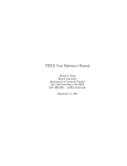
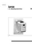
Instruction manual PROFINET IO-Device interface for digital multibus Mass Flow / Pressure instruments Doc. no.: 9.17.095B Date: 28-09-2015 ATTENTION Please read this instruction manual carefully before installing and operating the instrument. Not following the guidelines could result in personal injury and/or damage to the equipment. Head Office: Nijverheidsstraat 1a, NL‐7261 AK Ruurlo, The Netherlands, Tel. +31 573 458800, [email protected] BRONKHORST® Disclaimer Even though care has been taken in the preparation and publication of the contents of this manual, we do not assume legal or other liability for any inaccuracy, mistake, mis‐statement or any other error of whatsoever nature contained herein. The material in this manual is for information purposes only, and is subject to change without notice. Bronkhorst High‐Tech B.V. September 2015 Symbols Important information. Discarding this information could cause injuries to people or damage to the Instrument or installation. Helpful information. This information will facilitate the use of this instrument. Additional info available on the internet or from your local sales representative. Warranty The products of Bronkhorst High‐Tech B.V. are warranteed against defects in material and workmanship for a period of three years from the date of shipment, provided they are used in accordance with the ordering specifications and the instructions in this manual and that they are not subjected to abuse, physical damage or contamination. Products that do not operate properly during this period may be repaired or replaced at no charge. Repairs are normally warranted for one year or the balance of the original warranty, whichever is the longer. See also paragraph 9 of the Conditions of sales: http://www.bronkhorst.com/files/corporate_headquarters/sales_conditions/en_general_terms_of_sales.pdf The warranty includes all initial and latent defects, random failures, and undeterminable internal causes. It excludes failures and damage caused by the customer, such as contamination, improper electrical hook‐up, physical shock etc. Re‐conditioning of products primarily returned for warranty service that is partly or wholly judged non‐warranty may be charged for. Bronkhorst High‐Tech B.V. or affiliated company prepays outgoing freight charges when any party of the service is performed under warranty, unless otherwise agreed upon beforehand. However, if the product has been returned collect to our factory or service center, these costs are added to the repair invoice. Import and/or export charges, foreign shipping methods/carriers are paid for by the customer. Page 2 PROFINET interface 9.17.095 BRONKHORST® Table of contents 1 GENERAL PRODUCT INFORMATION .................................................................................................... 4 1.1 INTRODUCTION ............................................................................................................................................. 4 1.2 MULTIBUS TYPES ........................................................................................................................................... 4 1.3 REFERENCES TO OTHER APPLICABLE DOCUMENTS ................................................................................................... 5 1.3.1 Manuals and user guides: ........................................................................................................................... 5 1.3.2 Technical Drawings: .................................................................................................................................... 5 1.3.3 Software tooling: ........................................................................................................................................ 5 1.4 SHORT FORM START‐UP ................................................................................................................................... 6 1.5 FUNDAMENTALS OF PROFINET........................................................................................................................ 7 2 PROFINET INSTALLATION ................................................................................................................... 8 2.1 INSTRUMENT OVERVIEW .................................................................................................................................. 8 2.2 PIN ASSIGNMENT ........................................................................................................................................... 8 2.3 CONNECTION CABLES ...................................................................................................................................... 9 2.4 PROFINET CONNECTION ................................................................................................................................ 9 2.5 PROFINET BUS TERMINATION ......................................................................................................................... 9 2.6 POWER CONNECTOR ....................................................................................................................................... 9 3 CONFIGURATION .............................................................................................................................. 10 3.1 GSDML‐FILE ............................................................................................................................................. 10 3.2 CONFIGURATION SOFTWARE ........................................................................................................................... 10 3.3 LOAD GSDML‐FILE ...................................................................................................................................... 10 3.4 ADD SLAVE TO PROFINET IO ........................................................................................................................ 11 3.5 SLAVE CONFIGURATION SETTINGS .................................................................................................................... 12 3.6 CYCLIC PARAMETER ACCESS ............................................................................................................................ 13 3.7 A‐CYCLIC PARAMETER ACCESS. ........................................................................................................................ 14 4 SLAVE ADDRESSING .......................................................................................................................... 15 4.1 GENERAL ................................................................................................................................................... 15 4.2 MAC ADDRESS ........................................................................................................................................... 15 4.3 IP ADDRESS AND DEVICE NAME ....................................................................................................................... 15 4.4 FACTORY RESET. .......................................................................................................................................... 15 5 SAFE STATE ...................................................................................................................................... 16 6 TROUBLESHOOTING ......................................................................................................................... 17 6.1 PROFINET STATUS INDICATOR ....................................................................................................................... 17 6.1.1 PROFINET run state indicator .................................................................................................................... 17 6.1.2 PROFINET link state indicator ................................................................................................................... 17 6.2 INSTRUMENT LED INDICATION ........................................................................................................................ 18 6.3 TROUBLESHOOTING HINTS AND TIPS ................................................................................................................. 19 7 SERVICE ............................................................................................................................................ 20 8 APPENDIX A: A‐CYCLIC PARAMETER INDICES .................................................................................... 21 Page 3 PROFINET interface 9.17.095 BRONKHORST® 1 GENERAL PRODUCT INFORMATION 1.1 INTRODUCTION This manual will explain how to install a Bronkhorst1 instrument to your PROFINET system. It only contains information which is needed most. More detailed information about PROFINET can be obtained on the website of the (international) PROFINET organization: www.profibus.com or on the website of the (local) PROFINET organization of your country (when available). Example of a Bronkhorst instrument with PROFINET interface 1) Bronkhorst: This includes Bronkhorst High‐Tech B.V. , Bronkhorst Cori‐Tech B.V. and M+W Instruments GmbH. 1.2 MULTIBUS TYPES The Bronkhorst High‐Tech digital instruments offers great flexibility thanks to the “multibus” concept, whereby the instruments can be equipped with an on‐board interface with DeviceNet™, Profibus‐DP®, PROFINET®, Modbus, EtherCAT® or FLOW‐BUS protocol. Page 4 PROFINET interface 9.17.095 BRONKHORST® 1.3 REFERENCES TO OTHER APPLICABLE DOCUMENTS Manuals and guides for digital instruments are modular. General instructions give information about the functioning and installation of instruments. Operational instructions explain the use of the digital instruments features and parameters. Fieldbus specific information explains the installation and use of the field bus installed on the instrument. 1.3.1 Manuals and user guides: General instructions Instrument type based Operational instructions Document 9.17.022 Field bus specific information Document 9.17.023 Bronkhorst High‐Tech General instructions digital Mass Flow / Pressure Document 9.17.024 FLOW‐BUS interface Operational instructions for digital multibus Mass Flow / Pressure instruments Document 9.17.031 Bronkhorst Cori‐Tech General instructions CORI‐FLOW Document 9.17.050 Bronkhorst Cori‐Tech General instructions mini CORI‐FLOW Document 9.17.044 Bronkhorst High‐Tech General instructions digital LIQUI‐FLOW L30 Document 9.17.025 PROFIBUS–DP interface Document 9.17.026 DeviceNet interface Document 9.17.035 Modbus interface Document 9.17.027 RS232 interface with FLOW‐BUS protocol M+W Instruments Instruction manual MASS‐STREAM D‐6300 Document 9.17.063 EtherCAT interface Document 9.17.095 PROFINET interface 1.3.2 Technical Drawings: Hook‐up diagram MBC3 laboratory‐style PROFINET 1.3.3 (document nr. 9.16.147) Software tooling: FlowDDE GSDML file All these documents can be found at: http://www.bronkhorst.com/en/downloads Page 5 PROFINET interface 9.17.095 BRONKHORST® 1.4 SHORT FORM START‐UP All necessary settings for this module are already performed at Bronkhorst. To follow next steps carefully is the quickest way to get this module operational in your own PROFINET environment. START Master present Make sure your master has been installed to the PROFINET system Load GSDML Load GSDML‐file into the configuration tool (software at PROFINET master). Identify device on network. Setup IP address and device name Perform a network scan to identify the devices connected to the network. Setup the device’s IP‐address and device name. Add PROFINET IO‐Device to system Select "Bronkhorst meter/controller" and add new instrument to the bus (with configuration tool). Add module “Standard flowmeter” to PROFINET IO device Depending on the instrument type a “module” can be added to slot 1 of the PROFINET IO‐Device. NOTE: at this point, the GSDML‐file only supports Standard flowmeter. Submodules can be added to the subslots of the module. The submodules represent the parameters of the device (i.e. measure or setpoint). These modules will be read/written cyclically. Add submodules Download configuration Download all configuration settings into your master. Test data‐exchange communication between your master and the instrument(s). Test data exchange Ready Page 6 PROFINET interface 9.17.095 BRONKHORST® 1.5 FUNDAMENTALS OF PROFINET The PROFINET protocol is 100% Ethernet‐compatible and is used for data exchange between IO‐Controllers (PLC, etc.) and IO‐Devices (slaves, field devices). It uses the proven communication model and application view of PROFIBUS DP and extends it by Ethernet as the communication medium. Simple PROFINET system. PROFINET is a master/slave bus system. Bronkhorst instruments are all slaves. There is no mutual communication between PROFINET slaves, only between a master and slave. The cycle time is 8 ms. The slaves are addressed using MAC addresses and IP addresses. The figure below shows a network that comprises two subnets. These are represented by the different Network‐IDs (subnet mask). For PROFINET IO field devices, address resolution is based on the symbolic name of the device, to which a unique MAC address is assigned. After the system is configured, the engineering tool loads all information required for data exchange to the IO‐Controller, including the IP addresses of the connected IO‐Devices. Based on the name (and the associated MAC address), an IO‐Controller can recognize the configured field devices and assign them the specified IP addresses using the DCP protocol (Discovery and Configuration Protocol) integrated in PROFINET IO. Alternatively, addressing can be performed via a DHCP serve Following address resolution, the system powers up and parameters are transmitted to the IO‐Devices. The system is then available for productive data traffic. Master configuration software. The IP‐address and Device name can be configured with the Master configuration software. For example: PROFINET Master Simulator from Bihl + Wiedemann (used in this manual). Step 7 from Siemens for PLC type S7‐300 2DP. Most master configuration software tools work in the same way, because PROFINET is a standardized fieldbus system. Only on details and program operation things could be different. Read user manual carefully for correct operation of other programs than Sycon and Step 7. Bronkhorst tooling software: eq FlowDDE and FlowView The Bronkhorst tooling software is able to communicate with the instrument via RS232 using a special cable. If you don’t have such a cable ask your local sales representative. Page 7 PROFINET interface 9.17.095 BRONKHORST® 2 PROFINET INSTALLATION 2.1 INSTRUMENT OVERVIEW Instrument LED indication (Red/Green) Manual Interface (see 9.17.023) PROFINET STATUS indicator DB9 connector for power MAC‐address label Link/Activity led PROFINET connector 2.2 PIN ASSIGNMENT RJ45 Connector Receptacle 1 Pin number Wire color 1 Yellow Transmit + 2 Orange Transmit ‐ 3 White Receive + 4 Not used 5 Not used 6 Blue Receive ‐ 7 Not used 8 Not used 8 Description Page 8 PROFINET interface 9.17.095 BRONKHORST® 2.3 CONNECTION CABLES For a robust communication it is advised to use the dedicated PROFINET cable that uses a 4‐wire robust quad cable. The electrical performance is optimised for 100Base‐Tx and shielded against interference. Example of a PROFINET cable More information about PROFINET cables can be found at: http://www.profibus.com 2.4 PROFINET CONNECTION The Bronkhorst instruments are equipped with two RJ45 connectors. Both connectors can be used as input or output. One of the PROINET RJ45 connectors can be used to connect the instrument with the PROFINET master and the other RJ45 connector can be used to connect to another PROFINET instruments. According to IEC 802.3 the maximum cable length for 100 MBaud Ethernet is 100m (100BaseT), e.g. between two instruments. 2.5 PROFINET BUS TERMINATION A bus terminator (e.g. using bus terminating resistors) is not necessary. 2.6 POWER CONNECTOR The instrument is powered through the DB9 connector. DB9 Connector Receptacle Pin number 4 7 Description 0V Power +V power For more details of the possibilities of the DB9 connector see Hook‐up diagram (document nr. 9.16.147). Page 9 PROFINET interface 9.17.095 BRONKHORST® 3 CONFIGURATION 3.1 GSDML‐FILE Each type PROFINET instrument has its own GSDML‐file with instrument specifications to tell the master configuration software which facilities/features the instruments offers to the PROFINET system. For Bronkhorst meter/controller the file is called: GSDML‐Vx.y‐BHT‐Flowmeters‐yyyymmdd.xml. This file is available on the Multibus documentation/software tool CD and describes the whole Bronkhorst product range. The most actual version of the GSDML‐file cables can be found at: http://www.bronkhorst.com The GSDML file is a xml file containing: ‐ Device identification info: Here you can find general information about the GSDML file like: o Vendor (Bronkhorst) o Vendor ID (0x02F3) o Product family. ‐ Device Access Point (DAP) information. This contains information about: o Used hardware o Ethernet related settings o Supported features. ‐ Modules Modules represent Bronkhorst devices (i.e. Flowmeters, pressure controllers etc.). Modules can be assigned to a slot of the PROFINET IO‐Device. Depending on the hardware, 1 to 3 modules can be assigned. ‐ Submodules Submodules represent the variables of the Module. Submodules can be added to the cyclic IO by assigning them to a subslot of the corresponding slot. 3.2 CONFIGURATION SOFTWARE In this manual we use as an example the software tool “PROFINET Master Simulator” from Bihl + Wiedemann. 3.3 LOAD GSDML‐FILE The GSDML‐file must be loaded into the configuration software. Page 10 PROFINET interface 9.17.095 BRONKHORST® 3.4 ADD SLAVE TO PROFINET IO The configuration software is able to scan the PROFINET for devices. After a “new scan” the Bronkhorst flowmeter will be detected. The MAC address of the device is shown. In the example below the MAC‐address is 00:A0:45:00:00:09. Each instrument has its own unique MAC address. The user can change the IP address, subnet mask and gateway settings (see screenshot below). Page 11 PROFINET interface 9.17.095 BRONKHORST® 3.5 SLAVE CONFIGURATION SETTINGS Bronkhorst PROFINET instruments offer many available modules/parameters for operation of the instruments. These modules/parameters can be selected by means of the master configuration tooling software. After installing the slave to the PROFINET system, point to actual slave and select: [setup]. In the first table (left) the available module(s) are listed. Select the module(s) you want to use. The selected module(s) will be displayed in the second table (right). Select the “Standard flowmeter” module from the list of available modules. As next step the cyclic parameters you want to use in your application can be selected from the “Useable Submodules”‐list. In the example below the flow measurement “Measure, integer (read)” is selected. The selected submodule is displayed in the right list. Page 12 PROFINET interface 9.17.095 BRONKHORST® 3.6 CYCLIC PARAMETER ACCESS The parameters of the instrument can be accessed cyclically by its name, e.g.: “Measure, integer (read)": to access the measurement value “Setpoint, integer (write)": write the setpoint to the controller Proc/Param Cyclic Parameter Measure, integer (read) 1/0 Alarm minimum limit (write) 97/2 Fmeasure, float (read) 33/0 Alarm mode (read) 97/3 Setpoint, integer (read) 1/1 Alarm mode (write) 97/3 Setpoint, integer (write) 1/1 Alarm setpoint mode (read) 97/5 Fsetpoint, float (read) 33/3 Alarm setpoint mode (write) 97/5 Fsetpoint, float (write) 33/3 Alarm new setpoint (read) 97/6 Analog input (read) 1/3 Alarm new setpoint (write) 97/6 Temperature (read) 33/7 Alarm delay time (read) 97/7 Actual density (read) 116/15 Alarm delay time (write) 97/7 Control mode (read) 1/4 Reset alarm enable (read) 97/9 Control mode (write) 1/4 Reset alarm enable (write) 97/9 Setpoint slope (read) 1/2 Counter value (read) 104/1 104/2 Cyclic Parameter Proc/Param 1/2 Counter unit (read) Valve output (read) 114/1 Counter limit (read) 104/3 Valve output (write) 114/1 Counter limit (write) 104/3 Fluid number (read) 1/16 Counter setpoint mode (read) 104/5 Fluid number (write) 1/16 Counter setpoint mode (write) 104/5 Fluid name (read) 1/17 Counter new setpoint (read) 104/6 Capacity 100 % (read) 1/13 Counter new setpoint (write) 104/6 Capacity 0 % (read) 33/22 Counter unit string (read) 104/7 Capacity unit string (read) 1/31 Counter mode (read) 104/8 Calibration mode (read) 115/1 Counter mode (write) 104/8 Calibration mode (write) 115/1 Reset counter enable (read) 104/9 Serial number (read) 113/3 Reset counter enable (write) 104/9 BHT Model number (read) 113/2 Counter controller overrun correction (read) 104/10 104/10 Setpoint slope (write) Firmware version (read) 113/5 Counter controller overrun correction (write) Identification number (read) 113/12 Counter controller gain (read) 104/11 Device type (read) 113/1 Counter controller gain (write) 104/11 Usertag (read) 113/6 Alarm info (read) 1/20 Usertag (write) 113/6 Reset (write) 115/8 Customer model number (read) 113/4 Initreset (write) Alarm maximum limit (read) 97/1 IO switch status (read) 114/31 Alarm maximum limit (write) 97/1 IO switch status (write) 114/31 Alarm minimum limit (read) 97/2 0/10 More information about modules/parameters or an example of counter and alarm usage can be found in the manual “917023 Operational instructions digital instruments”. The description of the parameter can be found in the manual by searching for the process/parameter (Proc/Param), e.g. search for “1/0” to find the definition of “Measure, integer (read)”. This document can be found at: http://www.bronkhorst.com/en/downloads/instruction_manuals/ Page 13 PROFINET interface 9.17.095 BRONKHORST® 3.7 A‐CYCLIC PARAMETER ACCESS. All parameters can be read/written using A‐cyclic communication. To address these parameters, a parameter index is used. This index is built of: 1 An instance ID. This is the flowmeter instance. In case of a single channel device the instance ID is always 0 and refers to the device on slot 1. In case of a multichannel device 0 = MFC on slot 1. 1 = MFC on slot 2. 2 = MFC on slot 3. 2 A process number. Process numbers are listed in the “Parameter list in FlowDDE” or the parameter table in chapter 3.6. 3 A parameter number. Parameter numbers are listed in the “Parameter list in FlowDDE” or the parameter table in chapter 3.6. The a‐cyclic parameter index can be calculated as follows Index = (instance * 4096) + (process * 32) + parameter A list with frequently used parameters can be found in appendix A. Page 14 A‐cyclic requests must be addressed to the hardware ID of the Profinet interface (slot 0‐Head). PROFINET interface 9.17.095 BRONKHORST® 4 SLAVE ADDRESSING 4.1 GENERAL Addressing a PROFINET IO‐Device is done by means of a device name and IP‐addresses. 4.2 MAC ADDRESS The MAC address of the device is an unique address and is listed on the sticker on the device. The MAC address cannot be changed but can be used to identify the device on the network. 4.3 IP ADDRESS AND DEVICE NAME When configuring the PROFINET IO network, each device is given a logical device name to identify the device. The user is free to choose the name. An IP‐address is also assigned to the device. This IP address is unique within the network. 4.4 FACTORY RESET. The PROFINET factory reset, sets the ip‐address, subnetmask, gateway and device name to their default values. The PROFINET factory reset does not apply to the device functions. For resetting the device’s factory settings, please refer to the user manual 9.17.023. Page 15 PROFINET interface 9.17.095 BRONKHORST® 5 SAFE STATE If PROFINET communication problems occur, so when instrument is not in data exchange mode, the instrument forces the valve (controllers only) into a safe state mode. This safe state depends on the type of valve. NC valves will be closed, NO valves will be opened fully. The green and red Led on top of the instrument indicates this mode by a short flash: 0.1 sec on, 2 sec off. As long as there is no data exchange between master and slave the instrument will stay in this mode. It will leave this mode automatically when data exchange starts. Via the RS232 communication interface it is possible to force the instrument out of the safe state by changing the control mode to a value other than 0. At for example control mode = 18 (RS232) or control mode = 1 (Analog input) the instrument will not get into safe state. Page 16 PROFINET interface 9.17.095 BRONKHORST® 6 TROUBLESHOOTING 6.1 PROFINET STATUS INDICATOR Bronkhorst instruments contain an PROFINET two color status led: green and red. The led indicates the actual PROFINET run state (green) and the actual link state (red). The status led has several indicator states, which are applicable for both green and red. They are described in the table below. PROFINET status indicator: Green: Run state Red: Link state Indicator state Definition on off blinking single flash The indicator is constantly on The indicator is constantly off The indicator is repeatedly on for 200 ms and off for 200 ms The indicator is repeatedly on for 200 ms and off for 1000 ms The indicator shows repeatedly a sequence of two short flashes (200 ms), separated by an off phase (200 ms), followed by a long off phase (1000 ms) double flash 6.1.1 PROFINET run state indicator Run state Indicator state (green) PROFINET interface not started (yet) PROFINET interface in Init state PROFINET interface started correctly off blinking on 6.1.2 PROFINET link state indicator Link status Indicator state (red) Application relation established with IO‐controller Link status OK, No Application relation with IO‐controller No link. off blinking on Page 17 PROFINET interface 9.17.095 BRONKHORST® 6.2 INSTRUMENT LED INDICATION Instrument LED indication Green and Red Led Time Green off on short flash Continuously Continuously 0.1 sec on, 2 sec off normal flash Red off short flash long flash on Wink Mode normal wink slow wink fast wink Page 18 0.2 sec on, 0.2 sec off Indication Power‐off or program not running Normal running/operation mode Initialization mode Secured parameters can be changed Safe state active Special function mode Instrument is busy performing any special function. E.g. auto‐zero or self‐test Continuously No error, application relation established. 0.1 sec on, No application relation established. 2 sec off 2 sec on, Configuration error. For example, a requested parameter is not 0.1 sec off available. Continuously Critical error in PROFINET interface hardware Red Green Green Red turn by turn 0.2 sec on, Wink mode 0.2 sec off By a command send via PROFINET the instrument can “wink” with Led’s to indicate its position in a (large) system 1 sec on, Alarm indication: minimum alarm, limit/maximum alarm; power‐ 1 sec off up alarm or limit exceeded or batch reached. 0.1 sec on, Switch‐released, selected action started 0.1 sec off PROFINET interface 9.17.095 BRONKHORST® 6.3 TROUBLESHOOTING HINTS AND TIPS PROFINET problems No Communication Flow is not reacting to setpoint commands Red Led has long flash Check power supply and cabling. Check all PROFINET settings at your master. Master and slave settings for use of memory modules must be the same. Select at least one module e.g. ‘Measure, integer (read)’ otherwise there will be no data‐exchange. Check IP address, Subnetmask and gateway settings of interface (slave) Try to reset the instrument and/or restart your master. Make sure all settings for your slave are downloaded to your master (otherwise it won’t work). Contact PROFINET sales representative or service department. In case of PROFINET communication problems instrument will put it’s valve into a safe state. This will close (NC) or open the valve fully (NO). When data exchange between master and slave has been re‐established, instrument will respond to setpoint again. For overruling safe state via RS232 interface, see setpoint /control modes in chapter 2.5 from doc. nr. 9.17.023, (digital instrument description). Make sure the requested parameters are available in the particular Bronkhorst PROFINET‐slave. Delete the PROFINET slave configuration and add a new slave in your software, this will remove a corruption in the software configuration. Page 19 PROFINET interface 9.17.095 BRONKHORST® 7 SERVICE For current information on Bronkhorst and service addresses please visit our website: http://www.bronkhorst.com Do you have any questions about our products? Our Sales Department will gladly assist you selecting the right product for your application. Contact sales by e‐mail: [email protected] For after‐sales questions, our Customer Service Department is available with help and guidance. To contact CSD by e‐ mail: [email protected] No matter the time zone, our experts within the Support Group are available to answer your request immediately or ensure appropriate further action. Our experts can be reached at: +31 573 45 88 39 Page 20 PROFINET interface 9.17.095 BRONKHORST® 8 APPENDIX A: A‐CYCLIC PARAMETER INDICES Parameter name: Measure Fmeasure Setpoint Fsetpoint Analog Input Temperature Actual Density Control mode Setpoint slope Valve output Fluid number Fluid name Capacity 100% Capacity 0% Capacity unit string Calibration mode Serial number BHT model number Firmware Version Identification number Device type Usertag Customer model number Alarm maximum limit Alarm minimum limit Alarm mode Alarm setpoint mode Alarm new setpoint Alarm delay time Reset alarm enable Counter value Counter unit Counter limit Counter setpoint mode Counter new setpoint Counter unit string Counter mode Reset counter enable Counter controller overrun correction Counter controller gain Alarm info Reset Initreset IO swich status Page 21 Type: integer float integer float integer float float integer integer integer integer string float float string integer string string string integer string string string integer integer integer integer integer integer integer float integer float integer integer string integer integer float float integer integer integer integer Process 1 33 1 33 1 33 116 1 1 114 1 1 1 33 1 115 113 113 113 113 113 113 113 97 97 97 97 97 97 97 104 104 104 104 104 104 104 104 104 104 1 115 0 114 Instance: 0 Instance: 1 Instance: 2 Parameter Length: Index (Dec): Index (Hex): Index (Dec): Index (Hex): Index (Dec): Index (Hex): 0 2 32 0x20 4128 0x1020 8224 0x2020 0 4 1056 0x420 5152 0x1420 9248 0x2420 1 2 33 0x21 4129 0x1021 8225 0x2021 3 4 1059 0x423 5155 0x1423 9251 0x2423 3 2 35 0x23 4131 0x1023 8227 0x2023 7 4 1063 0x427 5159 0x1427 9255 0x2427 15 4 3727 0xE8F 7823 0x1E8F 11919 0x2E8F 4 1 36 0x24 4132 0x1024 8228 0x2024 2 2 34 0x22 4130 0x1022 8226 0x2022 1 4 3649 0xE41 7745 0x1E41 11841 0x2E41 16 1 48 0x30 4144 0x1030 8240 0x2030 17 10 49 0x31 4145 0x1031 8241 0x2031 13 4 45 0x2D 4141 0x102D 8237 0x202D 22 4 1078 0x436 5174 0x1436 9270 0x2436 31 7 63 0x3F 4159 0x103F 8255 0x203F 1 1 3681 0xE61 7777 0x1E61 11873 0x2E61 1 20 3617 0xE21 7713 0x1E21 11809 0x2E21 2 23 3618 0xE22 7714 0x1E22 11810 0x2E22 5 6 3621 0xE25 7717 0x1E25 11813 0x2E25 12 1 3628 0xE2C 7724 0x1E2C 11820 0x2E2C 1 6 3617 0xE21 7713 0x1E21 11809 0x2E21 6 16 3622 0xE26 7718 0x1E26 11814 0x2E26 4 16 3620 0xE24 7716 0x1E24 11812 0x2E24 1 2 3105 0xC21 7201 0x1C21 11297 0x2C21 2 2 3106 0xC22 7202 0x1C22 11298 0x2C22 3 1 3107 0xC23 7203 0x1C23 11299 0x2C23 5 1 3109 0xC25 7205 0x1C25 11301 0x2C25 6 2 3110 0xC26 7206 0x1C26 11302 0x2C26 7 1 3111 0xC27 7207 0x1C27 11303 0x2C27 9 1 3113 0xC29 7209 0x1C29 11305 0x2C29 1 4 3329 0xD01 7425 0x1D01 11521 0x2D01 2 1 3330 0xD02 7426 0x1D02 11522 0x2D02 3 4 3331 0xD03 7427 0x1D03 11523 0x2D03 5 1 3333 0xD05 7429 0x1D05 11525 0x2D05 6 2 3334 0xD06 7430 0x1D06 11526 0x2D06 7 4 3335 0xD07 7431 0x1D07 11527 0x2D07 8 1 3336 0xD08 7432 0x1D08 11528 0x2D08 9 1 3337 0xD09 7433 0x1D09 11529 0x2D09 10 4 3338 0xD0A 7434 0x1D0A 11530 0x2D0A 11 4 3339 0xD0B 7435 0x1D0B 11531 0x2D0B 20 1 52 0x34 4148 0x1034 8244 0x2034 8 1 3688 0xE68 7784 0x1E68 11880 0x2E68 10 1 10 0xA 4106 0x100A 8202 0x200A 31 4 3679 0xE5F 7775 0x1E5F 11871 0x2E5F PROFINET interface 9.17.095