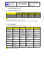
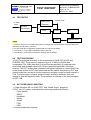
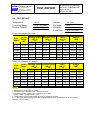
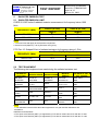
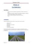
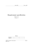
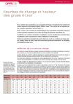
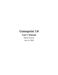
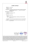
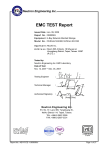
1
Spectrum Research
& Testing Lab., Inc.
No. 101-10, Ling 8,
Shan-Tong Li, Chung-Li
City, Taoyuan, Taiwan,
R.O.C.
TEST REPORT
Reference No.:A03062405
Report No.:FCBA03062405
Page:2 of 15
Date:Jul. 01, 2003
Table of Contents
1.
1.1
1.2
2.
2.1
2.2
2.3
2.4
3.
4.
4.1
4.2
4.3
4.4
4.5
4.6
5.
5.1
5.2
5.3
5.4
5.5
5.6
6.
7.
DOCUMENT POLICY AND TEST STATEMENT................................................ 3
DOCUMENT POLICY ........................................................................................ 3
TEST STATEMENT............................................................................................ 3
DESCRIPTION OF EUT AND TEST MODE ...................................................... 4
GENERAL DESCRIPTION OF EUT .................................................................. 4
DESCRIPTION OF EUT INTERNAL DEVICE.................................................... 4
DESCRIPTION OF TEST MODE....................................................................... 4
DESCRIPTION OF SUPPORT UNIT ................................................................. 5
DESCRIPTION OF APPLIED STANDARDS ...................................................... 5
CONDUCTED EMISSION TEST........................................................................ 6
CONDUCTED EMISSION LIMIT........................................................................ 6
TEST EQUIPMENT............................................................................................ 6
TEST SETUP ..................................................................................................... 7
TEST PROCEDURE .......................................................................................... 7
EUT OPERATING CONDITION ......................................................................... 7
TEST RESULT ................................................................................................... 8
RADIATED EMISSION TEST............................................................................. 9
RADIATED EMISSION LIMIT............................................................................. 9
TEST EQUIPMENT............................................................................................ 9
TEST SET-UP...................................................................................................10
TEST PROCEDURE .........................................................................................11
EUT OPERATING CONDITION ........................................................................11
RADIATED EMISSION TEST RESULT.............................................................12
PHOTOS OF TESTING.................................................................................... 13
TERMS OF ABRIVATION................................................................................. 15
Spectrum Research
& Testing Lab., Inc.
No. 101-10, Ling 8,
Shan-Tong Li, Chung-Li
City, Taoyuan, Taiwan,
R.O.C.
1.
TEST REPORT
Reference No.:A03062405
Report No.:FCBA03062405
Page:3 of 15
Date:Jul. 01, 2003
DOCUMENT POLICY AND TEST STATEMENT
1.1 DOCUMENT POLICY
- The report shall not be reproduced except in full, without the written approval of
SRT Lab, Inc.
- The report must not be used by the applicant to claim that the product is
endorsed by NVLAP, TÜV, NEMKO and SRT.
- The NVLAP logo applies only to the applicable standards specified in this report.
1.2 TEST STATEMENT
- The test results in the report apply only to the unit tested by SRT Lab.
- There was no deviation from the requirements of test standards during the test.
- AC power source, 120 Vac/60 Hz, was used during the test.
Spectrum Research
& Testing Lab., Inc.
No. 101-10, Ling 8,
Shan-Tong Li, Chung-Li
City, Taoyuan, Taiwan,
R.O.C.
TEST REPORT
Reference No.:A03062405
Report No.:FCBA03062405
Page:4 of 15
Date:Jul. 01, 2003
2. DESCRIPTION OF EUT AND TEST MODE
2.1 GENERAL DESCRIPTION OF EUT
PRODUCT
MODEL NO.
POWER SUPPLY
CABLE
Switch Hub 8 Port
ES-3108 V9.0
DC from an external power adaptor
Brand: DVE
Model No.: DV-1250AC-B16
I/P: 120VAC 60Hz
O/P: 12VAC 500mA
Unshielded power cable (1.5m)
N/A
NOTE :
For more detailed information, please refer to the EUT’s specification or user’s manual provided by
manufacturer.
2.2 DESCRIPTION OF EUT INTERNAL DEVICE
DEVICE
BRAND / MAKER
MODEL #
N/A
NOTE :
1. The highest clock is 25MHz.
2. Frequency range to be measured.
Radiated emission is 30 MHz to 1 GHz.
2.3
DESCRIPTION OF TEST MODE
N/A (It is only applicable to more than one test mode.)
FCC ID/DOC
REMARK
Spectrum Research
& Testing Lab., Inc.
No. 101-10, Ling 8,
Shan-Tong Li, Chung-Li
City, Taoyuan, Taiwan,
R.O.C.
TEST REPORT
Reference No.:A03062405
Report No.:FCBA03062405
Page:5 of 15
Date:Jul. 01, 2003
2.4 DESCRIPTION OF SUPPORT UNIT
The EUT was configured by the requirement of ANSI C63.4:1992 and
CISRP22:1997. All interface ports were connected to the appropriate support units
via specific cables. The support units and cables are listed below.
NO
DEVICE
BRAND
MODEL #
FCC ID / DOC
CABLE
1.5m unshielded power cord
1.2m shielded data cable
1.5m unshielded power cord
1.2m shielded data cable
1.5m unshielded DC power cable
1.2m shielded data cable
1
MONITOR
SAMSUNG
PG17IS
DOC
2
PRINTER
EPSON
STYLUS
C20SX
DOC
3
MODEM
ACEEX
DM-1414
DOC
4
KEYBOARD
ACER
6311-TA
DOC
1.2m unshielded data cable
5
MOUSE
LOGITECH
M-S34
DZL210472
1.2m unshielded data cable
6
PC
COMPAQ
D51C/P2.4/40/K/
DOC
256C
1.5m unshielded power cord
NOTE : For the actual test configuration, please refer to the photos of testing.
3. DESCRIPTION OF APPLIED STANDARDS
The EUT is a kind of ITE and according to the specifications provided by the
applicant, it must comply with the requirements of the following standards:
47 CFR Part 15 Subpart B, Class B
All tests have been performed and recorded as per the above standards.
Spectrum Research
& Testing Lab., Inc.
TEST REPORT
No. 101-10, Ling 8,
Shan-Tong Li, Chung-Li
City, Taoyuan, Taiwan,
R.O.C.
4.
CONDUCTED EMISSION TEST
4.1
CONDUCTED EMISSION LIMIT
FREQUENCY (MHz)
0.15 - 0.5
0.5 - 5.0
5.0 - 30.0
Class A (dBµV)
Quasi-peak
Average
79
66
60
73
73
60
Reference No.:A03062405
Report No.:FCBA03062405
Page:6 of 15
Date:Jul. 01, 2003
Class B (dBµV)
Quasi-peak
Average
66 - 56
56 - 46
56
46
60
50
NOTE:
1. The lower limit shall apply at the transition frequencies.
2. The limit decreases in line with the logarithm of the frequency in the range of 0.15 to 0.50 MHz.
4.2 TEST EQUIPMENT
The following test equipment was used for the test:
EQUIPMENT/
FACILITIES
EMI TEST
RECEIVER
LISN (for EUT)
LISN
(for Peripheral)
50 ohm
TERMINATOR
COAXIAL
CABLE
ISOLATION
TRANSFORMER
FILTER
SPECIFICATIONS MANUFACTURER
9 kHz TO
30 MHz
50 µH, 50 ohm
50µH, 50 ohm
50 ohm
HP
3m
SUNCITY
N/A
APC
2 LINE, 30A
FIL.COIL
2.3M (H) x
2.4M (W)
2.4M (H) x
GROUND PLANE
2.4M (W)
GROUND PLANE
ROHDE &
SCHWARZ
SOLAR
ELECTRONICS
SOLAR
ELECTRONICS
MODEL#/
SERIAL#
ESHS30/
826003/008
8012-50-R-24-BNC
/ 924839
9252-50-R-24-BNC
/ 951318
11593A/
2
J400/
3M
AFC-11015/
F102040016
FC-943/
771
SRT
N/A
SRT
N/A
DUE DATE OF CAL.
& CAL. CENTER
JUL. 2003
R&S
JUN. 2004
ETC
JUN. 2004
ETC
MAY 2004
ETC
JUL. 2003
SRT
N/A
N/A
APR. 2004
SRT
APR. 2004
SRT
NOTE: The calibration interval of the above test equipment is one year and the calibrations are
traceable to NML/ROC and NIST/USA.
Spectrum Research
& Testing Lab., Inc.
No. 101-10, Ling 8,
Shan-Tong Li, Chung-Li
City, Taoyuan, Taiwan,
R.O.C.
TEST REPORT
Reference No.:A03062405
Report No.:FCBA03062405
Page:7 of 15
Date:Jul. 01, 2003
4.3 TEST SETUP
EMI TEST
Receiver
To Utility
Power
Coaxial Cable
Isolation
Transformer
Filter
LISN
EUT
LISN
Support Units
NOTE:
1. The EUT was put on a wooden table with 0.8m height above ground plane, and 0.4m away from
reference ground plane (> 2mx2m).
2. For the actual test configuration, please refer to the photos of testing.
3. The serial no. of the LISN connected to EUT is 951318.
4. The serial no. of the LISN connected to support units is 924839.
4.4 TEST PROCEDURE
The EUT was tested according to the requirement of ANSI C63.4:1992 and
CISRP22:1997. The frequency spectrum from 0.15 MHz to 30 MHz was
investigated. The LISN used was 50 ohm/50µH as specified. All readings were
quasi-peak and average values with 10 kHz resolution bandwidth of the test
receiver. The EUT system was operated in all typical methods by users. Both lines
of the power mains of EUT were measured and the cables connected to EUT and
support units were moved to find the maximum emission levels for each frequency.
First, Find the margin or higher points at least 6 points by software, then use
manual to find the maximum data. The procedure is referred on the test procedure
of SRT LAB.
4.5 EUT OPERATING CONDITION
1. Under Windows XP ran “EMI TEST” and “Media Player” programs.
2. EUT sent "H" pattern or accessed the following peripherals directly:
- Color Monitor
- RS232
- Keyboard
- Mouse
- Printer
- FDD
- HDD
3. Accessed data from internet.
Spectrum Research
& Testing Lab., Inc.
TEST REPORT
No. 101-10, Ling 8,
Shan-Tong Li, Chung-Li
City, Taoyuan, Taiwan,
R.O.C.
Reference No.:A03062405
Report No.:FCBA03062405
Page:8 of 15
Date:Jul. 01, 2003
4.6 TEST RESULT
Temperature:
24 °C
Humidity:
54 %RH
Ferquency Range:
0.15 – 30 MHz
Test Mode:
N/A
Receiver Detector:
Q.P. and AV.
Tested By:
Alen Chou
Tested Date:
Jun. 25, 2003
Power Line Measured : Line
Freq.
(MHz)
0.152
2.090
2.640
4.560
9.240
20.000
Correct. Reading Value Emission Level
Factor
(dBµV)
(dBµV)
(dB)
Q.P.
AV.
Q.P.
AV.
0.20
33.0
33.2
0.20
14.8
15.0
0.20
16.3
16.5
0.31
25.3
25.6
0.39
15.7
16.1
0.60
22.8
23.4
-
Limit
(dBµV)
Q.P.
65.9
56.0
56.0
56.0
60.0
60.0
AV.
55.9
46.0
46.0
46.0
50.0
50.0
Margin
(dB)
Q.P.
-32.7
-41.0
-39.5
-30.4
-43.9
-36.6
AV.
N/A
N/A
N/A
N/A
N/A
N/A
Power Line Measured : Neutral
Freq.
(MHz)
0.151
0.293
4.060
4.590
8.750
20.000
Correct. Reading Value Emission Level
Factor
(dBµV)
(dBµV)
(dB)
Q.P.
AV.
Q.P.
AV.
0.20
33.9
34.1
0.20
17.8
18.0
0.30
19.1
19.4
0.31
18.8
19.1
0.38
18.8
19.2
0.60
23.2
23.8
-
Limit
(dBµV)
Q.P.
65.9
60.4
56.0
56.0
60.0
60.0
AV.
55.9
50.4
46.0
46.0
50.0
50.0
Margin
(dB)
Q.P.
-31.8
-42.4
-36.6
-36.9
-40.8
-36.2
NOTE :
1. Measurement uncertainty is +/-2dB
2. Emission level = Reading value + Correction factor
3. Correction Factor = Cable loss + Insertion loss of LISN
4. Margin value = Emission level - Limit
5. The emission of other frequencies were very low against the limit.
6. "-": The Quasi-peak reading value also meets average limit and measurement with the average
detector is unnecessary.
AV.
N/A
N/A
N/A
N/A
N/A
N/A
Spectrum Research
& Testing Lab., Inc.
No. 101-10, Ling 8,
Shan-Tong Li, Chung-Li
City, Taoyuan, Taiwan,
R.O.C.
TEST REPORT
Reference No.:A03062405
Report No.:FCBA03062405
Page:9 of 15
Date:Jul. 01, 2003
5.
RADIATED EMISSION TEST
5.1 RADIATED EMISSION LIMIT
CISPR 22:1997 limits of radiated emission measurement for frequency below 1000
MHz
Class A (at 10m)
Class B (at 10m)
dBµV/m
dBµV/m
30 – 230
40
30
230 - 1000
47
37
FREQUENCY (MHz)
NOTE:
1. The lower limit shall apply at the transition frequencies.
2. Emission level (dBµV/m) = 20 log Emission level (µV/m).
FCC Part 15, Subpart B limit of radiated emission for frequency above 1 GHz
Class B (dBµV/m) (at 3m)
FREQUENCY (MHz)
PK.
AV.
Above 1000
74.0
54.0
5.2 TEST EQUIPMENT
The following test equipment was used during the radiated emission test:
EQUIPMENT/
FACILITIES
EMI TEST
RECEIVER
BI-LOG
ANTENNA
SPECIFICATIONS MANUFACTURER
9 kHz TO
2750 MHz
25 MHz TO
2 GHz
3 – 10 M
MEASUREMENT
ROHDE &
SCHWARZ
COAXIAL
CABLE
25M
SUNCITY
FILTER
2 LINE, 30A
FIL.COIL
FREQUENCY
CONVERTER
N/A
APC
OATS
EMCO
SRT
MODEL#/
SERIAL#
ESCS30/
830245/012
3142/
9701-1124
SRT-1
J400/
25M
FC-943/
869
AFC-1KW/
860612
DUE DATE OF CAL. &
CAL. CENTER
AUG. 2003
R&S
APR. 2004
SRT
APR. 2004
SRT
JUL. 2003
SRT
N/A
JUL. 2003
SRT
NOTE:
1. The calibration interval of the above test equipment is one year and the calibrations are
traceable to
NML/ROC and NIST/USA.
2. The Open Area Test Site (SRT-1) is registered by FCC with No. 90957 and VCCI with No. R-1081.
3. The Open Area Test Site (SRT-2) is registered by FCC with No. 98458 and VCCI with No. R-1168.
Spectrum Research
& Testing Lab., Inc.
No. 101-10, Ling 8,
Shan-Tong Li, Chung-Li
City, Taoyuan, Taiwan,
R.O.C.
TEST REPORT
Reference No.:A03062405
Report No.:FCBA03062405
Page:10 of 15
Date:Jul. 01, 2003
5.3 TEST SET-UP
Turn Table
1m – 4m
EUT
Coaxial
Power Cable
0.8 m
Cable
3/10m
Filter
To Utility
Power
Ground Plane
EMI Receiver
NOTE :
1. The EUT system was put on a wooden table with 0.8m heights above a ground plane.
2. For the actual test configuration, please refer to the photos of testing.
Spectrum Research
& Testing Lab., Inc.
No. 101-10, Ling 8,
Shan-Tong Li, Chung-Li
City, Taoyuan, Taiwan,
R.O.C.
TEST REPORT
Reference No.:A03062405
Report No.:FCBA03062405
Page:11 of 15
Date:Jul. 01, 2003
5.4 TEST PROCEDURE
The EUT was tested according to the requirement of ANSI C63.4:1992 and CISPR
22:1997. The measurements were made at an open area test site with 10 meter
measurement distance under 1 GHz and with 3m distance above 1GHz. The
frequency spectrum measured started from 30 MHz. Under 1 GHz, all readings
were quasi-peak values with 120 kHz resolution bandwidth of the test receiver.
Above 1 GHz, the measurements were made at an open area test site with 3 meter
measurement distance and all readings were peak or average values with 1 MHz
resolution bandwidth of the test receiver. The EUT system was operated in all
typical methods by users. The cables connected to EUT and support units were
moved to find the maximum emission levels for each frequency.
First, Find the margin or higher points at least 6 points by software, then use
manual to find the maximum data. The procedure is referred on the test procedure
of SRT LAB.
5.5 EUT OPERATING CONDITION
Same as section 4.5 of this report.
Spectrum Research
& Testing Lab., Inc.
No. 101-10, Ling 8,
Shan-Tong Li, Chung-Li
City, Taoyuan, Taiwan,
R.O.C.
Reference No.:A03062405
Report No.:FCBA03062405
Page:12 of 15
Date:Jul. 01, 2003
TEST REPORT
5.6 RADIATED EMISSION TEST RESULT
Temperature:
31 °C
Humidity:
56 %RH
Ferquency Range:
30 – 1000 MHz
Measured Distance:
10m
Receiver Detector:
Q.P.
Tested Mode:
N/A
Tested By:
Alen Chou
Tested Date:
Jun. 25, 2003
Antenna Polarization:Horizontal
Frequency
(MHz)
200.0112
220.0115
500.0684
550.0745
800.0469
900.1234
Cable Antenna Reading Emission
Loss
Factor
Data
Level
(dB)
(dB/m)
(dBµV)
(dBµV/m)
1.63
1.76
2.96
3.07
3.05
2.91
9.90
10.50
18.60
19.60
23.00
23.70
15.9
14.6
9.6
6.8
6.3
7.2
27.4
26.9
31.2
29.5
32.4
33.8
Limit
Margin
(dBµV/m)
(dB)
30.0
30.0
37.0
37.0
37.0
37.0
-2.6
-3.1
-5.8
-7.5
-4.7
-3.2
Limit
Margin
(dBµV/m)
(dB)
30.0
30.0
30.0
37.0
37.0
37.0
-3.6
-2.9
-4.8
-4.0
-4.5
-3.7
AZ(°)
EL(m)
23.6
259.8
128.0
332.8
326.9
328.1
2.03
1.86
1.66
1.72
1.51
1.84
AZ(°)
EL(m)
263.0
0
125.3
203.7
351.5
223.3
1.00
1.00
1.00
1.00
1.52
1.95
Antenna Polarization:Vertical
Frequency
(MHz)
66.5210
200.0012
220.0112
500.0684
700.1260
900.1235
Cable Antenna Reading Emission
Loss
Factor
Data
Level
(dB)
(dB/m)
(dBµV)
(dBµV/m)
1.02
1.63
1.76
2.96
2.76
2.91
7.30
9.90
10.50
18.60
21.90
23.70
18.1
15.6
12.9
11.4
7.8
6.7
26.4
27.1
25.2
33.0
32.5
33.3
NOTE :
1. Measurement uncertainty is +/-4dB.
2. "*": Measurement does not apply for this frequency.
3. Emissiom Level = Reading Value + Ant. Factor + Cable Loss.
4. The field strength of other emission frequencies were very low against the limit.
Spectrum Research
& Testing Lab., Inc.
No. 101-10, Ling 8,
Shan-Tong Li, Chung-Li
City, Taoyuan, Taiwan,
R.O.C.
6.
PHOTOS OF TESTING
- Conducted test
TEST REPORT
Reference No.:A03062405
Report No.:FCBA03062405
Page:13 of 15
Date:Jul. 01, 2003
Spectrum Research
& Testing Lab., Inc.
No. 101-10, Ling 8,
Shan-Tong Li, Chung-Li
City, Taoyuan, Taiwan,
R.O.C.
- Radiated test
TEST REPORT
Reference No.:A03062405
Report No.:FCBA03062405
Page:14 of 15
Date:Jul. 01, 2003
Spectrum Research
& Testing Lab., Inc.
No. 101-10, Ling 8,
Shan-Tong Li, Chung-Li
City, Taoyuan, Taiwan,
R.O.C.
7.
TEST REPORT
Reference No.:A03062405
Report No.:FCBA03062405
Page:15 of 15
Date:Jul. 01, 2003
TERMS OF ABRIVATION
AV.
Average detection
AZ(°)
Turn table azimuth
Correct.
Correction
EL(m)
Antenna height (meter)
EUT
Equipment Under Test
Horiz.
Horizontal direction
LISN
Line Impedance Stabilization Network
NSA
Normalized Site Attenuation
Q.P.
Quasi-peak detection
SRT Lab
Spectrum Research & Testing Laboratory, Inc.
Vert.
Vertical direction