1
Flashlite 386Ex User’s Manual
JK microsystems
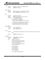
The DATA and IER registers also hold the baud rate divisor. When the high bit of the LCR
(DLA) is set, the divisor value can be written to DATA and IER. DATA contains the low byte and
IER contains the high byte. To determine the required divisor, divide 115200 by the required
baud rate. Program the divisor with the nearest integer value. When access to the divisor value
is no longer required, clear the DLA bit.
RS-485 Configuration
The COM2 port of the Flashlite can be configured and used for RS-485 communications. In
order to avoid conflicts with DOS and the BIOS, it is first necessary to move the console to
COM1. This is done using the utility program CON2COM1. Please note that COM1 (J6) is
pinned out as DTE and you must use a null modem cable to connect it to a PC serial port.
To enable RS-485 operation (and disable RS-232) on COM2, clear bit 6 of I/O port F872 hex.
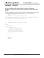
#define EN485_MASK 0xBF
#define EN485_REG 0xF872
outportb(EN485_REG, (inportb(EN485_REG) & EN485_MASK) ); // change to RS-485
Bit 0 of the PINCFG register must be set to allow control of the RS-485 transmit enable pin. The
PINCFG register is located at I/O port F826 hex.
#define PINCFG 0xF826
outportb(PINCFG, (inportb(PINCFG) | 0x01) ); // connect TE to chip pkg
The RTS line on COM2 is used to control the RS-485 transmitter. To transmit RS-485 data, set
bit 1 of I/O port 2FC hex (mirrored at F8FC hex). To receive RS-485 data, clear bit 1. Note that
the state of the chip pin is the inverse of the bit in the register (register=1, pin=0).
#define TX_MASK 0x02
#define TX_MASK_REG 0xF8FC
outportb(TX_MASK_REG, (inportb(TX_MASK_REG) | TX_MASK) ); // enable tx
outportb(TX_MASK_REG, (inportb(TX_MASK_REG) & ~TX_MASK) ); // disable tx
Two utility programs are available to aid RS-485 development. 485RX accepts RS-485 data and
displays it on the console. 485TX accepts console data and sends it out the RS-485 port. The
console must be switched to COM1 when using the utilities. These programs are installed on
drive A:.
Watchdog Circuitry
The Flashlite has two Watchdog protection features. The Hardware Watchdog is part of the reset
control chip and the Watchdog Timer is a feature of the 386Ex processor chip.
The Hardware Watchdog requires that software write to a specific I/O port before its timer
expires. If the timer expires, a system wide reset is issued and the board will restart. This is the
preferred watchdog due to its ability to generate a hardware reset. JP2 must be installed to enable
the Hardware Watchdog.
The BIOS will reset the Hardware Watchdog for approximately 5 seconds after power up giving
the user application enough time to load. The user application must write a 0C hex to I/O
location FF04 hex at least once every 1.6 seconds.
Hardware
9