1
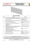
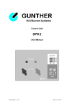
EMUFDD 4.25 – USB USER MANUAL The most reliable and configurable Universal Floppy HW Emulator ALL-INCLUSIVE PROFESSIONAL INSTALLATION SERVICE AVAILABLE Custom/non-standard floppies analysis & development available USB Version Network Version Section 1. Section 2. Section 3. Section 4. Section 5. Section 6. Section 7. Section 8. Section 9. Section 10. Section 11. Section 12. DATASHEET HARDWARE INSTALLATION INTRODUCTION & EMULATION CYCLE SOFTWARELESS MODE STORAGE VIRTUAL-FLOPPY MODE STORAGE LOADING INTO EMUFDD'S MEMORY FROM USB SAVING FROM EMUFDD'S MEMORY TO USB FORMATTING EMUFDD'S MEMORY AND USB LOADING A CONFIGURATION SWITCHING CONFIGURATION SOFTWARELESS MODE ON/OFF AUTOSAVE ON/OFF Appendix A. Appendix B. FLOPPY DISK DRIVE INTERFACES TEAC FLOPPY DRIVES JUMPERING MILO S.N.C. SW & HW per Automazione - Industrial Automation SW & HW Via Ruggiero Grieco 1/C, 41011 Campogalliano (MO), Italy Codice Fiscale / Fiscal Code: 03373570369 - P.IVA / VAT: 03373570369 Tel. 059/528512 - Fax. 059/520131 - Email: [email protected] - Web: www.milosrl.it EMUFDD 4.25 – USB USER MANUAL - LAST REVISION SEPTEMBER 2012 P. 1/29 Section 1. DATASHEET DIMENSIONS Height [H] 1'' = Width [W] 4'' = 10,2 cm Depth [D] 5,3'' = 13,5 cm Weight 2,5 cm 300 g HARDWARE 1.5 MB FRAM non-volatile memory Internal Memory Type Internal Memory Reliability User Interface 1014 R/W cycles = 438.000 h = 50 years USB keys with FAT32 format – 100 floppy disks Ethernet 10T network – unlimited floppy disks Power On Time Less than (<) 500 ms Floppy Interface 34 pin flat cable (3.5'' & 5.25'') + 5V power supply 26 pin flat cable (integrated power supply) 26 pin slim cable (integrated power supply) SOFTWARE FIRMWARE RELEASE Revision 25 (September 2012) FLOPPY CONFIGURATION Jumperfree / Plug'n'Play – loading USB key USER ACCESS & PROTECTION Jumperfree / Plug'n'Play – loading USB key FIRMWARE UPGRADE SUPPORT EMULATION SUPPORT Plug'n'Play – loading USB key Any drive geometry (Tr/He/Se/Bytes) TRACKS x Disk = 01 ÷ 82 HEADS x Disk = 01 ÷ 02 SECTORS X TRACK = 01 ÷ 36 BYTES X SECTOR = 128 ÷ 4096 EMUFDD 4.25 – USB USER MANUAL - LAST REVISION SEPTEMBER 2012 P. 2/29 EMUFDD Tech-Homepage : www.embeddedsw.net Designer & Customer Support : [email protected] EMUFDD Product-Homepage : www.milosrl.it Manufacturer & Purchasing : [email protected] ALL-INCLUSIVE PROFESSIONAL INSTALLATION SERVICE AVAILABLE Floppy disk total configurability: Encoding, Rotation speed and drive geometry. ENCODING FM 125 KHz – 300 rpm MFM 250 KHZ – 300 rpm FM 150 KHZ – 360 rpm MFM 300 KHZ – 360 rpm FM 250 KHZ – 300 rpm MFM 500 KHZ – 300 rpm FM custom 125 ÷ 250 KHz MFM custom 250 ÷ 500KHZ FAT SUPPORT Softwareless Mode: 360 KB / 720 KB / 1.200 MB / 1.440 MB SOME COMMON 82/2/18x512 – MFM: 500 KHz – 300 rpm – 1.476 MB 81/2/18x512 – MFM: 500 KHz – 300 rpm – 1.441 MB EXAMPLES... 80/2/18x512 – MFM: 500 KHz – 300 rpm – 1.440 MB 80/2/15x512 – MFM: 500 KHz – 360 rpm – 1.200 MB 80/2/9x512 – MFM: 250 KHz – 300 rpm – 720 KB 80/2/9x512 – MFM: 300 KHz – 360 rpm – 720 KB 40/2/9x512 – MFM: 250 KHz – 300 rpm – 360 KB MORE LESS COMMON EXAMPLES... OLD & RARE EXAMPLES... 80/2/8x1024 – MFM: 500 KHz – 300 rpm – 1.280 MB 80/2/32x256 – MFM: 500 KHz – 300 rpm – 1.280 MB 80/2/26x256 – MFM: 500 KHz – 300 rpm – 1.040 MB 80/2/5x1024 – MFM: 250 KHz – 300 rpm – 800 KB 80/2/18x256 – MFM: 250 KHz – 300 rpm – 720 KB 80/2/16x256 – MFM: 250 KHz – 300 rpm – 640 KB 80/2/2x4096 – MFM: 500 KHz – 300 rpm – 1.280 MB 80/2/4x2048 – MFM: 500 KHz – 300 rpm – 1.280 MB 80/2/5x1024 – FM: 250 KHz – 300 rpm – 800 KB 80/2/9x512 – FM: 250 KHz – 300 rpm – 720 KB 80/2/18x256 – FM: 250 KHz – 300 rpm – 720 KB 80/2/32x128 – FM: 250 KHz – 300 rpm – 640 KB 80/2/18x128 – FM: 125 KHz – 300 rpm – 360 KB 80/2/16x128 – FM: 125 KHz – 300 rpm – 320 KB NEED MORE? Ask customer support for help in identifying your floppy disk! EMUFDD 4.25 – USB USER MANUAL - LAST REVISION SEPTEMBER 2012 P. 3/29 Section 2. HARDWARE INSTALLATION EMUFDD installation works like any other real floppy drive installation: 2.1) connect the power supply; = +12V power supply (not connected) Optional = two GND lines (joined, connect one or both) Required = +5V power supply Required 2.2) connect the 34pin flat cable. = pin-1 mark (flat cable / connector) No system driver or additional software needs to be installed on the host system. Be sure to match the connector pin-1 mark with the flat cable pin–1 mark ! Sometimes flat cables are inverted. Please check whether the cable is coloured/marked at pin-1 (standard) or pin-34 (inverted) ! EMUFDD 4.25 – USB USER MANUAL - LAST REVISION SEPTEMBER 2012 P. 4/29 Section 3. INTRODUCTION & EMULATION CYCLE EMUFDD is equipped with 1.5 MB of internal FRAM non-volatile memory: no need to keep the USB key plugged in; top-quality data storage and memory reliability (1014 read/write cycles); unlimited permanent internal memory (no battery, fully RoHS). More than 50 years of non-stop read/write emulation at full speed. Each EMUFDD can be used by different users with different skills: normal users can be allowed to load-only floppy disks (playback); advanced users can have full access to the program floppy disks; special floppy disks can be permanently write protected; simplified access available: 1 USB key = 1 floppy disk. Just ask for your version, fully customized for your everyday's usage ! At power-on EMUFDD immediately (less than 500ms) begins its emulation cycle: the emulation engine waits for reading or writing requests from the host system, and any read/write floppy disk access will turn the ACT_LED on; the display continuously shows the On-Line sequence: [– ] / [ –] / [NN], where NN is the current floppy disk number, (from 00 to 99). Snapshot of a display On-Line sequence (NN = 01). EMUFDD 4.25 – USB USER MANUAL - LAST REVISION SEPTEMBER 2012 P. 5/29 Section 4. SOFTWARELESS MODE STORAGE Data can be loaded/saved into/from EMUFDD's memory using any USB key. No special software or partitioning is needed to access and copy'n'paste all the floppy disks. The softwareless mode, a.k.a. “Translation”, splits all the floppy disks into subdirectories and each “emufddNN.dir” subdirectory (NN from 00 to 99) will be handled as the root of a different floppy disk: USB key X:\emufddNN.dir\dir1\file1.ext X:\emufddNN.dir\dir2\file2.ext X:\emufddNN.dir\file3.ext X:\emufddNN.dir\file4.ext ... ↔ ↔ ↔ ↔ ↔ EMUFDD (floppy NN) A:\dir1\file1.ext A:\dir2\file2.ext A:\file3.ext A:\file4.ext ... The translation feature: is available for 360 KB, 720 KB, 1.200 MB, 1.440 MB floppy disks; is available for both loading and saving; will truncate filenames to 8+3 short form (Longname.ext → longna~1.ext); can be enabled/disabled at anytime without reconfiguring (SECTION 11). EMUFDD 4.25 – USB USER MANUAL - LAST REVISION SEPTEMBER 2012 P. 6/29 [top window] USB key (H:) in the PC server [bottom window] EMUFDD (A:) in the machinery [top window] USB key (H:) in the PC server [bottom window] EMUFDD (A:) in the machinery EMUFDD 4.25 – USB USER MANUAL - LAST REVISION SEPTEMBER 2012 P. 7/29 [top window] USB key (H:) in the PC server [bottom window] EMUFDD (A:) in the machinery [top window] USB key (H:) in the PC server [bottom window] EMUFDD (A:) in the machinery EMUFDD 4.25 – USB USER MANUAL - LAST REVISION SEPTEMBER 2012 P. 8/29 [top window] USB key (H:) in the PC server [bottom window] EMUFDD (A:) in the machinery A diff between the original disk#00 in the USB key (H:\emufdd00.dir\cpyteca.cmd) and its “translated” version by EMUFDD (A:\cpyteca.cmd) shows that there's no high-level difference in the directory structure and the attributes of each file: Name / Size / Creation time / Modify time / Access time EMUFDD 4.25 – USB USER MANUAL - LAST REVISION SEPTEMBER 2012 P. 9/29 Section 5. VIRTUAL-FLOPPY MODE STORAGE Data can be loaded/saved into/from EMUFDD's memory using any USB key. No special software or partitioning is needed to copy'n'paste all the floppy disks. The virtual-floppy mode, a.k.a. “ISO FLOPPY IMAGE FILES”, splits all the floppy disks into image files (mounted on any PC using free software VFD) and each “emufddNN.img” file (NN from 00 to 99) will be handled as the low-level snapshot of a different floppy disk: USB key X:\emufddNN.img ↔ ↔ ↔ EMUFDD (floppy NN) <floppy> track0/side0/sector1 <floppy> track0/side0/sector2 ... Virtual-Floppy image files: are available for both loading and saving; are a low-level snapshot of the floppy disk surface; allow unlimited emulation of any floppy disk (system, bootable, custom, …); can be directly mounted as virtual floppy drives by free software VFD; can be directly imported as backups of real floppies by free software OmniFlop; can be enabled/disabled at anytime without reconfiguring (SECTION 11). EMUFDD 4.25 – USB USER MANUAL - LAST REVISION SEPTEMBER 2012 P. 10/29 [top window] USB key (H:) in the PC server [bottom window] EMUFDD (A:) in the machinery [top window] USB key (H:) in the PC server [bottom window] EMUFDD (A:) in the machinery EMUFDD 4.25 – USB USER MANUAL - LAST REVISION SEPTEMBER 2012 P. 11/29 [top window] USB key (H:) in the PC server [bottom window] EMUFDD (A:) in the machinery [top window] USB key (H:) + VFD (B:) in the PC server [bottom window] EMUFDD (A:) in the machinery EMUFDD 4.25 – USB USER MANUAL - LAST REVISION SEPTEMBER 2012 P. 12/29 [top window] USB key (H:) + VFD (B:) in the PC server [bottom window] EMUFDD (A:) in the machinery A diff between the original disk#00 in the USB key (B:\cpyteca.cmd) and its “translated” version by EMUFDD (A:\cpyteca.cmd) shows that there's no high-level and low-level difference in the directory structure and the attributes of each file: Name / Size / Size on disk / Creation time / Modify time / Access time EMUFDD 4.25 – USB USER MANUAL - LAST REVISION SEPTEMBER 2012 P. 13/29 Section 6. LOADING INTO EMUFDD'S MEMORY FROM USB 6.1) plug the USB key in and go Off-Line: press LOAD; 6.2) OFF-LINE_LED turns on and the display shows [CH] while checking the USB key for floppy image files (and subdirectories, if translation is on). Should no USB device be plugged in, the displays shows [nd] and EMUFDD switches automatically back to On-Line mode; 6.3) the display shows the current floppy number. Select the floppy to be loaded changing the current number (short DOWN/UP pressure = –1/+1, long DOWN/UP pressure = fast rewind/forward). Missing floppies are shown as [NN], existing floppies are shown as [N.N.]. Only existing floppies can be loaded, pressing LOAD; 6.4) the display, while loading, shows [LO] and LOAD_LED / ACT_LED turn on, until loading end. Any loading error immediately stops loading and display shows [Er]. Successful loading ends with display showing again current floppy number and LOAD_LED / ACT_LED turned off; 6.5) being no button pressed, after 5 seconds, EMUFDD automatically switches back to On-Line mode. Feel free to plug the USB key safely off. EMUFDD 4.25 – USB USER MANUAL - LAST REVISION SEPTEMBER 2012 P. 14/29 Plugging the USB key off while loading will not damage the USB key but will force EMUFDD to reset with an inconsistent internal memory ! Loading completely overwrites EMUFDD's internal memory. The previous floppy, if not backed up before, can't be recovered ! CLICK HERE FOR A VIDEO-DEMO: LOADING INTO INTERNAL MEMORY FROM USB Load + Save can be used to create, without using a PC, multiple copies of an existing floppy on the USB key. For example: load NN and save it as NN+1, NN+2, NN+3, … EMUFDD 4.25 – USB USER MANUAL - LAST REVISION SEPTEMBER 2012 P. 15/29 Section 7. SAVING FROM EMUFDD'S INTERNAL MEMORY TO USB 7.1) plug the USB key in and go Off-Line: press SAVE; 7.2) OFF-LINE_LED turns on and the display shows [CH] while checking the USB key for floppy image files (and subdirectories, if translation is on). Should no USB device be plugged in, the displays shows [nd] and EMUFDD switches automatically back to On-Line mode; 7.3) the display shows the current floppy number. Select the floppy to be saved changing the current number (short DOWN/UP pressure = –1/+1, long DOWN/UP pressure = fast rewind/forward). Missing floppies are shown as [NN], existing floppyies are shown as [N.N.]. Both missing and existing floppies can be saved, pressing SAVE (missing ones are created, existing ones are overwritten); 7.4) the display, while saving, shows [SA] and SAVE_LED / ACT_LED turn on, until saving end. Any saving error immediately stops saving and display shows [Er]. Successful saving ends with display showing again current floppy number and SAVE_LED / ACT_LED turned off; 7.5) being no button pressed, after 5 seconds, EMUFDD automatically switches back to On-Line mode. Feel free to plug the USB key safely off. EMUFDD 4.25 – USB USER MANUAL - LAST REVISION SEPTEMBER 2012 P. 16/29 Plugging the USB key off while saving will damage the USB key. Plug the USB key off only after the OFF-LINE_LED (red) turns off ! Saving completely overwrites USB key's destination. The previous floppy, if not backed up before, can't be recovered ! CLICK HERE FOR A VIDEO-DEMO: SAVING FROM INTERNAL MEMORY TO USB Load + Save can be used to create, without using a PC, multiple copies of an existing floppy on the USB key. For example: load NN and save it as NN+1, NN+2, NN+3, … EMUFDD 4.25 – USB USER MANUAL - LAST REVISION SEPTEMBER 2012 P. 17/29 Section 8. FORMATTING EMUFDD'S INTERNAL MEMORY AND USB 8.1) plug the USB key in and go Off-Line: press SAVE; 8.2) OFF-LINE_LED turns on and the display shows [CH] while checking the USB key for subdirectories (format is allowed only when translation is on). Should no USB device be plugged in, the displays shows [nd] and EMUFDD switches automatically back to On-Line mode; 8.3) the display shows the current floppy number. Select the floppy to be formatted changing the current number (short DOWN/UP pressure = –1/+1, long DOWN/UP pressure = fast rewind/forward). Missing floppies are shown as [NN], existing floppyies are shown as [N.N.]. Both missing and existing floppies can be formatted pressing SAVE+LOAD (missing ones are created, existing ones are overwritten); 8.4) the display, while formatting, shows [FO] and SAVE_LED / LOAD_LED / ACT_LED turn on, until formatting end. Any formatting error immediately stops formatting and display shows [Er]. Successful formatting ends with display showing again current floppy number and SAVE_LED / LOAD_LED / ACT_LED turned off; 8.5) being no button pressed, after 5 seconds, EMUFDD automatically switches back to On-Line mode. Feel free to plug the USB key safely off. EMUFDD 4.25 – USB USER MANUAL - LAST REVISION SEPTEMBER 2012 P. 18/29 Plugging the USB key off while formatting will both damage the USB key and force EMUFDD to reset with an inconsistent internal memory. Plug the USB key off only after the OFF-LINE_LED (red) turns off ! Formatting completely overwrites USB key's destination. The previous floppy, if not backed up before, can't be recovered ! CLICK HERE FOR A VIDEO-DEMO: FORMATTING INTERNAL MEMORY AND USB Format is allowed only in softwareless mode (when translation is on) Check the supported formats (SECTION 4). EMUFDD 4.25 – USB USER MANUAL - LAST REVISION SEPTEMBER 2012 P. 19/29 Section 9. LOADING A CONFIGURATION EMUFDD configuration is plug'n'play and absolutely jumper-free. It's also possible to configure the emulator with up to 100 different configurations and switch, at run-time, between them. The first 10 configurations (c0÷c9) can be loaded with any custom setting, the other 90 configurations (0.0÷9.0) are fixed presets. 9.1) load a valid “emufdd.cfg” file into a USB key; Configuration files for any machinery/floppy drive/floppy disk will be provided for free, only after purchasing, writing to the customer support (Eng. Cosimo Oliboni, 7/7 direct line with the designer of EMUFDD) at [email protected] 9.2) plug the USB key in and go Off-Line: press LOAD; 9.3) the device will auto-reset (all leds blink very fast) and the display, while changing configuration, shows [cc]. Any configuration error immediately stops auto-reset and display shows [Er]; 9.4) load a valid floppy into memory (SECTION 6) or, if format is supported, format EMUFDD's memory (SECTION 8). EMUFDD 4.25 – USB USER MANUAL - LAST REVISION SEPTEMBER 2012 P. 20/29 Section 10. SWITCHING CONFIGURATION 10.1) with no USB key plugged in press SAVE+DOWN+UP; 10.2) select the new configuration (NN = c0÷c9, 0.0÷9.0) changing the current number (DOWN/UP pressure = –1/+1). Missing configurations are shown as [cN], existing configurations are shown as [c.N] and [N.N]. Only existing configurations can be loaded, pressing SAVE+LOAD; 10.3) the device will auto-reset (all leds blink very fast) and the display, while changing configuration, shows [cc]; 10.4) load a valid floppy into memory (SECTION 6) or, if format is supported, format EMUFDD's memory (SECTION 8). Example 1: Your device needs two (or more) different kinds of floppy disks. Base configuration (c0) is assigned to the boot disk, the following ones (c1/c2/...) are assigned to user programs with different formats (720 KB, 800 KB, 1.440 MB, ...). device is powered up; user selects base configuration and loads the boot image; user selects another configuration and loads/saves user programs. c0 (BOOT) c1 (720 KB) c2 (800 KB) Example 2: You own more different devices and need to use the floppy on only one of them at a time. Each device is assigned a configuration and you buy only 1 EMUFDD. EMUFDD is connected “on the fly” to device-i; user selects configuration-i and loads/saves a batch of work; EMUFDD is disconnected from device-i and user goes on to the next one. EMUFDD 4.25 – USB USER MANUAL - LAST REVISION SEPTEMBER 2012 P. 21/29 c0 (DEVICE-0) c1 (DEVICE-1) cN (DEVICE-N) Connecting an EMUFDD “on-the-fly” it's very easy. You only need to modify, on each machinery, the floppy flat and power supply cables with longer ones, coming out from the machinery/control. After this modify, connecting/disconnecting the EMUFDD will be as easy as connecting/disconnecting a USB key and fast, since there's no more need to open the machinery to reach the floppy cables. Here's a reconstruced flowchart about a plastic-injection company with two different kinds of Arburg and a Charmilles: ARBURG 275 ARBURG 270 CHARMILLES Before choosing the shared solution, be sure to check that your machinery supports “on the fly” connecting/disconnecting without resetting ! CLICK HERE FOR A VIDEO-DEMO: SWITCHING CONFIGURATION #00 / #89 CLICK HERE FOR A VIDEO-DEMO: SWITCHING CONFIGURATION #89 / #00 EMUFDD 4.25 – USB USER MANUAL - LAST REVISION SEPTEMBER 2012 P. 22/29 Section 11. SOFTWARELESS MODE ON/OFF The softwareless mode translation feature (SECTION 4) can be enabled/disabled at anytime without reconfiguring the device. 11.1) with no USB key plugged in press SAVE+UP; 11.2) the current translation configuration is shown as [tN] (N = 0/1 = disabled/enabled). Pressing SAVE+UP again causes the translation configuration to switch; 11.3) the device will auto-reset (all leds blink very fast) and the display shows the new translation configuration [tN]. CLICK HERE FOR A VIDEO-DEMO: SETTING TRANSLATION ON CLICK HERE FOR A VIDEO-DEMO: SETTING TRANSLATION OFF EMUFDD 4.25 – USB USER MANUAL - LAST REVISION SEPTEMBER 2012 P. 23/29 Section 12. AUTOSAVE ON/OFF The AutoSave option has been added to simplify EMUFDD everyday's usage. When AutoSave is enabled, you don't need to manually save the current work before loading a new floppy or formatting a new one: EMUFDD automatically saves its internal memory to the current working floppy before loading/formatting. machinery has written to the current floppy modifying it; you need to automatically save to USB key before loading the next working floppy. 12.1) with no USB key plugged in press SAVE+DOWN; 12.2) the current AutoSave configuration is shown as [AN] (N = 0/1 = disabled/enabled). Pressing SAVE+DOWN again causes the AutoSave configuration to switch; 12.3) the device will auto-reset (all leds blink very fast) and the display shows the new AutoSave configuration [AN]. CLICK HERE FOR A VIDEO-DEMO: SETTING AUTOSAVE ON CLICK HERE FOR A VIDEO-DEMO: SETTING AUTOSAVE OFF EMUFDD 4.25 – USB USER MANUAL - LAST REVISION SEPTEMBER 2012 P. 24/29 Appendix A. FLOPPY DISK DRIVE INTERFACES Floppy drive configurability: 34pin host interface. PIN DIR SIGNAL (PC) (NC) (CUSTOM) 2 Out Density Select Disk Change 0 (GND) / 1 (+5V) Disk Change / Ready 4 - Not connected Not connected Not connected 6 - Not connected Not connected Not connected 8 Out Index Hole Index Hole Index Hole 10 In Motor A Drive 0 Pin 10 12 In Drive B Drive 1 Pin 12 14 In Drive A Drive 2 Pin 14 16 In Motor B Motor Pin 16 18 In Step Dir Step Dir Step Dir 20 In Step Pulse Step Pulse Step Pulse 22 In Write Data Write Data Write Data 24 In Write Enable Write Enable Write Enable 26 Out Track 0 Track 0 Track 0 28 Out Write Protect Write Protect Write Protect 30 Out Read Data Read Data Read Data 32 In Head Select Head Select Head Select 34 Out Disk Change Ready 0 (GND) / 1 (+5V) Disk Change / Ready 1,3,5,7,9,11,13,15,17,19,21,23,25,27,29,31,33 = GND The 34pin interface is natively supported by EMUFDD. Example: 34pin host interface (TEAC FD-235HF-A529). EMUFDD 4.25 – USB USER MANUAL - LAST REVISION SEPTEMBER 2012 P. 25/29 Floppy drive configurability: 26pin host interface. PIN DIR SIGNAL 2 Out Index Hole 4 In Drive Sel 6 Out Disk Change 8 Out Ready 10 In Motor 12 In Step Dir 13 Out Density Select 14 In Step Pulse 16 In Write Data 18 In Write Enable 20 Out Track 0 22 Out Write Protect 24 Out Read Data 26 In Head Select 1,3,5 = +5V 7,9,13,15,17,19,21,23,25 = GND The 26pin interface, normal & slim pinout, is supported by EMUFDD using an adatper. Example: 26pin host interface (NEC FD1138C) – normal pinout. Example: 34pin-to-26pin slim adapter. EMUFDD 4.25 – USB USER MANUAL - LAST REVISION SEPTEMBER 2012 P. 26/29 Appendix B. TEAC FLOPPY DRIVES JUMPERING A1-A2 FG Short between FDD frame and DC 0V B1-B2 DS0 Drive select 0 (NC) Drive0 B2-C2 DS1 Drive select 1 (NC) Drive1 C1-D1 RY34 Ready output on Pin 34 Pin34 = Ready D1-D2 DC34 Disk Change output on Pin 34 Pin34 = Disk Change E1-E2 HA Density set automatically Pin02 = Disk Change E2-F2 HI2 Density set by HD IN on pin 2 F1-F2 HO2 Density (HD OUT) output on pin 2 EMUFDD 4.25 – USB USER MANUAL - LAST REVISION SEPTEMBER 2012 Pin02 = Density Select P. 27/29 FG FG Short between FDD frame and DC 0V A1-B1 DS0 Drive select 0 (NC) Drive0 B1-C1 DS1 Drive select 1 (NC) Drive1 A2-B2 DS2 Drive select 2 (NC) Drive2 B2-C2 DS3 Drive select 3 (NC) Drive3 C3-D3 REN Disable auto-recalibration D3-E3 ACD(a) Disable auto-checking E3-F3 ACD(b) Disable auto-checking D2-E2 RY34 Ready output on Pin 34 Pin34 = Ready E1-E2 DC34 Disk Change output on Pin 34 Pin34 = Disk Change E1-F1 DC2 Disk Change output on Pin 2 Pin02 = Disk Change G1-G2 HA Density set automatically F1-G1 HI2 Density set by HD IN on pin 2 F1-F2 HO2 Density (HD OUT) output on pin 2 F3-G3 IR Pin02 = Density Select LED on when: (Drive Select AND Ready) EMUFDD 4.25 – USB USER MANUAL - LAST REVISION SEPTEMBER 2012 P. 28/29 FG FG Short between FDD frame and DC 0V A1-B1 DS0 Drive select 0 (NC) Drive0 B1-C1 DS1 Drive select 1 (NC) Drive1 A2-B2 DS2 Drive select 2 (NC) Drive2 B2-C2 DS3 Drive select 3 (NC) Drive3 A4-B4 RY34 Ready output on Pin 34 Pin34 = Ready B4-C4 DC34 Disk Change output on Pin 34 Pin34 = Disk Change C3-C4 DC2 Disk Change output on Pin 2 Pin02 = Disk Change C4-D4 DC4 Disk Change output on Pin 4 Pin04 = Disk Change A3-B3 HA Density set automatically B3-C3 HI2 Density set by HD IN on pin 2 C3-D3 HO2 Density (HD OUT) output on pin 2 Pin02 = Density Select D3-D4 HO4 Density (HD OUT) output on pin 4 Pin04 = Density Select D1-D2 LHI ---or--- D2-E2 LHI HD IN low is high density D1-E1 LHO ---or--- E1-E2 LHO HD IN high is high density E2-F2 HMK Half mask for INDEX/READ-DATA F3-G3 NMK No mask for INDEX/READ-DATA F1-G1 IR LED on when: (Drive Select AND Ready) G1-G2 ML Motor on when: (Motor ON AND LED on) E4-F4 ACD Disable auto-checking G3-G4 REN Disable auto-recalibration E2-E3 HF ---or--- E3-E4 HF Must always be in for this version of drive EMUFDD 4.25 – USB USER MANUAL - LAST REVISION SEPTEMBER 2012 P. 29/29