1
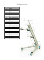
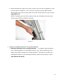
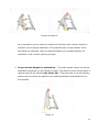
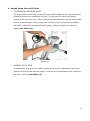
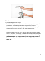
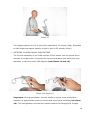
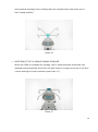
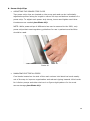
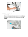
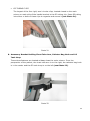
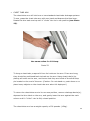
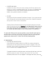
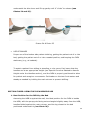
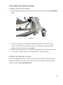
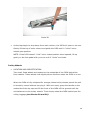
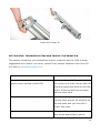
USER MANUAL Designed to improve mobility, safety, efficiency and storability. WWW.IVEAMOBILITY.COM CONTENTS IVEA Diagram & Legend ...................................................................................... 1 Introduction ...................................................................................................... 2 SECTION ONE: GENERAL CONSIDERATIONS Indications for Use .............................................................................................. 3 Types of Patient Care Departments Types of Patients Contraindications for Use ..................................................................................... 3 Types of Patient Care Departments Types of Patients Weight Capacity ................................................................................................. 3 Technical Data ................................................................................................... 4 Warnings ...................................................................................................... 5 Labels and Instruction ......................................................................................... 6 Removable Card No Standing on Legs Not Exceeding Weight Limitations Standard Product Label Regulatory Symbols Inspection for Biomedical Department ................................................................... 8 Out-of-the-box Inspection Inspection During General Use Environmental Considerations ............................................................................. 10 In Storage In Use Disposal ..................................................................................................... 11 SECTION TWO: AMBULATORY USE Features and Their Proper Use ............................................................................ 11 Preparation for Use ............................................................................................ 11 Handles ..................................................................................................... 11 Unfolding Handles for Use .............................................................................. 12 Handle Height Adjustment.............................................................................. 12 Folding the Handles Away for Storage or Non-use ............................................. 13 Special Concerns Related to Handle Height ....................................................... 14 Raising a Patient from a Sitting Position Proper Handle Height for Ambulation Angled Pump Pole .............................................................................................. 16 Attaching an Infusion Pump ............................................................................ 16 Raising the IV Pole ........................................................................................ 16 IV Hooks .................................................................................................... 17 Proper Placement and Weight ........................................................................ 17 Rotating IV Hooks Away From Patient .............................................................. 18 Position of the IV Hooks During Storage........................................................... 19 Power Strip Clips ............................................................................................... 20 Adjusting the Outlet Strip Clips ....................................................................... 20 Managing Electrical Cords .............................................................................. 20 IV Tubing and O2 Tubing Clips ............................................................................ 21 IV Tubing Clips ............................................................................................. 21 O2 Tubing Clips ............................................................................................ 22 Accessory Bracket (O2 tank hoop, chest tube arm, and catheter bag hook) .............. 22 Chest Tube Arm ............................................................................................ 23 Catheter Bag Hook ........................................................................................ 24 O2 Hoop ................................................................................................ 24 Caster Brakes ................................................................................................... 25 Location and Identification ............................................................................. 25 Use of Brakes ............................................................................................... 25 SECTION THREE: BEDSIDE USE Best Position for the IVEA by the Bed ................................................................... 26 Positioning the IV Pole ....................................................................................... 27 SECTION FOUR: STORAGE AND CLEANING Cleaning the IVEA .............................................................................................. 27 Storage Features and Their Proper Use................................................................. 28 Easy-Collapse Foot Pedal for Storage ................................................................... 28 Closing the IVEA for Storage Opening the IVEA from Storage Trolley Wheels .............................................................................................. 29 Location and Identification SECTION FIVE: TROUBLESHOOTING AND PRODUCT INFORMATION Troubleshooting ................................................................................................ 30 Product Warranty and Information ....................................................................... 32 IVEA Diagram & Legend Item No. Description 1. IV Hooks 2. Spring Buttons 3. IV Pole 4. Top Cap 5. Pole Adjustment Lever 6. Pump Pole 7. Handle Bracket 8. Handle Adjustment Lever 9. Handle Release Button 10. Handle Grip 11. IV Tubing/O2 Mgmt. Clips 12. Cord Hooks 13. Accessory Bracket 14. O2 Tank Hoop & Cup 15. Catheter Bag Hook 16. Chest Tube Arm 17. Power Strip Clips 18. Brace Bracket 19. Foot Pedal 20. Nose 21. Right Leg 22. Left Leg 23. Smooth-Gliding Casters 24. Brake Lever 1 INTRODUCTION Started by a former RN, Firefly Medical develops transformative patient-care equipment designed to improve the lives of patients and caregivers. The company’s first product, the IVEA, was developed with significant clinician input to improve mobility, safety, efficiency and storability. The IVEA is your med-surg mobility solution. It replaces the IV pole bedside, eliminating the need to transfer a patient’s equipment from one device to another. And it makes it possible for one caregiver to safely ambulate a patient. Easy to use, easy to clean and easy to store, it provides solutions to multiple challenges caregivers face every day. This manual provides operating instructions and product information in five main sections: 1. General Considerations 2. Ambulatory Use 3. Bedside Use 4. Storage and Cleaning 5. Troubleshooting and Product Information Every caregiver who uses the IVEA should read this manual and understand the equipment’s proper use. We also recommend that caregivers take time to get a feel for the equipment and how it moves before they use it with patients. NOTE: In the text, the term “caregiver” refers to nurses, physical therapists, aides, transport personnel and any other healthcare professionals who use the IVEA to provide patient care. NOTE: All adjustment points, i.e., buttons and levers, appear in blue in the various diagrams and photos and are blue on the IVEA itself. NOTE: Refer to the IVEA Diagram and Legend on Page 1 for a list of features. 2 SECTION ONE: GENERAL CONSIDERATIONS 1. Indications for use TYPES OF PATIENT CARE DEPARTMENTS The IVEA is intended for Med-Surg patient care. Relevant departments include, but aren’t limited to, Medical, Ortho, Post-Surgical, Oncology, Neuro, PostTrauma and some Cardiac Units. Names for these units may vary from one hospital to the next, but they generally comprise the majority of patient beds in a hospital. TYPES OF PATIENTS The IVEA replaces the IV pole entirely, both bedside and during ambulation. It’s recommended for use with any patient with supportive equipment, regardless of whether or not they are ambulatory. Mobile patients will benefit most from the IVEA, especially those needing ambulatory assistance. The IVEA is designed to organize and secure IVs, infusion pumps, chest tubes, catheter, drainage devices, O2, PCAs and feeding tubes, while offering a stable, ergonomic base to support a patient’s normal gait. 2. Contraindications for use TYPES OF PATIENT CARE DEPARTMENTS While the IVEA is not necessarily contraindicated for any particular department, the benefits of the IVEA are unlikely to be fully realized in a situation where the patient is comatose, under general anesthesia, confined to bed rest, unable to ambulate, or receiving short-term care that does not require infusions and other supportive therapies. TYPES OF PATIENTS Patients who require full weight-bearing assistance should not use the IVEA. While the IVEA is designed to help support a patient during ambulation, it’s not intended for full weight-bearing activity. Some bariatric patients and patients who, as a result of their physical limitations, might place excessive weight on the IVEA during ambulation, should not use the product. 3 3. Weight Capacity The IVEA has a maximum patient-weight limit of 300 pounds (136 kg). It was not designed to support a patient’s full weight. Caregivers should use their best judgement to determine whether the IVEA is the proper mobility equipment for a patient. Improper use by patients or caregivers could result in injury and/or damage to the IVEA. Improper uses include but are not limited to: Placing full weight on the unit Leaning on only one handle Riding the unit or standing on the legs Mounting or placing equipment on the unit that it was not designed to accommodate IV Pole Weight Capacity The weight capacity for the IV pole fully extended is 11 pounds (5Kg). Extended to half height the weight capacity of the IV pole is 22 pounds (10Kg.) 4. Technical Data: Dimensions folded (H x W x L) 320 mm x 330 mm x 1280 mm 46.8-84 in x 27.5 in x 28.7-38 in Dimensions unfolded 12.6 in x 13 in x 50.3 in (H x W x L) Height of handle (1190-2140 mm x 700 mm x 730-970 mm) 34.6-38 in (880-970 mm) grips Weight 29.5 lbs (13 kg) Max. patient weight 300 lbs (136 kg) Max. weight 267 lbs (121 kg) capacity 4 5. Warnings The following warnings and cautions apply to general use of the IVEA within a facility’s usual and customary parameters of patient care. These statements are not intended to anticipate or address problems that might result from policy noncompliance or irresponsible decision-making. WARNING! Use of the IVEA is not intended to replace or diminish professional caregiver judgment. Responsible consideration of a patient’s needs and abilities should govern any use of this product. WARNING! Special care should be taken when using the IVEA with patients considered to be at risk for falls. These patients include, but aren’t limited to, those who manifest specific intrinsic and extrinsic factors that may or may not have been identified through a risk assessment. WARNING! Improper use of the IVEA may result in injuries to the patient and/or the caregiver. Proper care must be taken to follow all instructions and to use the IVEA only as intended. WARNING! Improper and inadequate cleaning of the IVEA after patient use may increase the potential of hospital-acquired infections. Care must be taken to properly and completely clean the IVEA after each patient use. For more information about cleaning, see Servicing and Cleaning in this manual. WARNING! Pulling back on the IVEA’s handles may result in the product tipping backward. The potential for tipping increases if the brakes are engaged, the patient is sitting, and the handles are deployed in a high position. See more information under Handle Height Adjustment, under Features and Their Proper Use. WARNING! Attempts to ride or mount the IVEA may result in serious personal injury. The IVEA should not be used for any purpose for which it wasn’t designed. Do not stand on the legs, place full weight on the handles, or use the IVEA in any manner inconsistent with proper use. 5 WARNING! Do not ignore the weight parameters of IVEA. The IVEA has a maximum patient weight limit of 300 pounds (136 kg). WARNING! Use caution to avoid possible pinching injury. Keep fingers, feet and toes away from inner surfaces of the IVEA when collapsing product for storage. Use caution when folding and unfolding the handles to avoid pinching against the main column or portions of the handle bracket. WARNING! Avoid elevating IV bags during ambulation. If IV tubing is properly primed, an infusion pump reduces the need to elevate IV bags. Keep the height of the IV bags at least three inches below the patient’s chin during ambulation, in order to keep the patient’s field of vision clear. See Proper Height Considerations of IV Hooks under Features and Their Proper Use. WARNING! Do not modify the IVEA under any circumstances. If you have questions or concerns about the product, contact Firefly Medical at (970) 4725323, www.iveamobility.com. WARNING! Do not store or park the IVEA for extended periods in direct sunlight or near heat-radiating devices. WARNING! Do not use the IVEA outdoors or on terrain with inclines or declines. The IVEA is designed to roll easily and quietly over virtually any indoor surface, over gaps between flooring and elevators, and over changes in surface type. 6. Labels and Instructions REMOVABLE CARD WITH HELPFUL HINTS A laminated, lanyard-style card with helpful tips about the product and its use should be attached to the handle bracket eyelet when you receive your IVEA. Refer to this information as needed in order to become familiar with the features and functions of the equipment. NO STANDING ON LEGS A label at the rear of each leg warns against standing on the IVEA. 6 NOT EXCEEDING WEIGHT LIMITATIONS Language embossed on the top surface of the handle bracket states that the maximum patient weight limit for the equipment is 300 pounds (136 kg). STANDARD PRODUCT LABEL A product label providing standard manufacturing, regulatory and contact information is mounted on the underside of the equipment. REGULATORY SYMBOLS: Manufactured in China for Firefly Medical Inc., 320 E. Vine Dr., Suite 312, Fort Collins, CO 80524. ! Refer to User Manual for complete operating instructions, uses, serviceability and warnings. Read all directions before using. Serial number Date of manufacture (P/N) Finished device’s part number or reference number Approved for sale in the EEA 7 Disclaimer: This document may contain technical inaccuracies or typographical errors. Changes are periodically made to the information herein; these changes will be incorporated in future revisions of this document. Firefly Medical, Inc. does not accept any liability for the use or misuse, direct or indirect, of this product. Firefly Medical, Inc. does not accept any liability or responsibility for damages arising out of the use of or inability to use this product. 7. Inspection for Biomedical Department OUT-OF-THE-BOX INSPECTION The IVEA should arrive without obvious visible damage to the product or any of its components. If obvious visible damage has occurred, close up box and contact Customer Service at: (970) 472-5323, www.iveamobility.com. Minor assembly is required. Components and Assembly Instructions are included in the product box. Instructions are also available online. The box should include: o The IVEA o Four castor wheels o IV hook assembly o Assembly instructions o Instructions to access online User Manual INSPECTION AND PERIODIC ADJUSTMENTS This section reviews methods for periodic inspection of key components of the IVEA during routine patient use, including how to adjust them as needed. (NOTE: It may be necessary to have the Biomedical Department make adjustments). IV Pole Adjustment Lever: Check to insure that the IV pole is securely held in place when the pole adjustment lever is closed. To adjust the lever, open it fully. 8 Using a 3mm hex wrench, tighten the socket head screw clockwise no more than 30 degrees at a time, then close the lever and check for adequate clamping force. Repeat as needed (NOTE: Do not over-tighten). Run the IV pole through its entire telescopic range, checking for smooth operation. Handle Adjustment Lever: Check to insure that the handle bracket is securely held in place when the handle adjustment lever is closed. To adjust the lever, open it partially. Using a 5mm hex wrench, tighten the socket head screw clockwise no more than 30 degrees at a time (see Photo 1), then close the lever and check for adequate clamping force. (NOTE: Do not over-tighten). Photo 1 Handles: Deploy each handle up and away from the main column, until it “clicks” into its open locked position. Handles should disengage without excessive force on the blue release button. When in their stored position against the main column, the handles should not swing away from the main column under their own weight, even when the IVEA is folded and horizontal and is subjected to mild jarring. Casters and Brakes: Check each caster for free-spinning wheels. Remove hair and other debris that may impede rolling. Insure that each caster swivels freely 9 and remove any debris inhibiting rotation. Engage the blue brake lever of each caster and check to insure that both wheel and swivel lock securely. Chest Tube Arm and O2 Hoop: Deploy and store the chest tube arm and O2 hoop, checking for secure locking in both positions. These features should move from their deployed or stored positions only when their corresponding blue levers are depressed. Brace Bracket Lock Pin: Open the IVEA from its folded position and listen for a “click” when the lock pin engages, securing the main column in its upright position. When the lock pin is properly engaged, the foot pedal protrudes perpendicular to the main column and has light spring force maintaining it there. If the foot pedal feels “loose” when the IVEA is deployed, the lock pin is not properly engaged. Gas Spring: With the IVEA in its deployed state, gently depress the foot pedal. The main column should not move toward the floor unless moderate downward force is applied. General appearance: With routine use of the IVEA, the pump mount may show blemishes and scuff marks associated with mounting pumps and other equipment. These marks can be removed with normal cleaning. 8. Environmental Considerations The IVEA is designed for indoor use only. Optimal conditions for storage: o Temperature: 5°F - 122°F (-15°C - +50°C) o Humidity: 20% - 100% o Ambient air pressure: 26.6 – 32.5 InHg (900 – 1,100 hPa) Optimal conditions for use: o Temperature: 59°F - 104°F (-15°C - +40°C) o Humidity: 20% - 100% 10 o Ambient air pressure: 26.6 – 32.5 InHg (900 – 1,100 hPa) 9. Disposal This product can be safely recycled at a recycling center or discarded in the institution’s standard trash collection receptacle. PLEASE RECYCLE. SECTION TWO: AMBULATORY USE In this section the assumption is made that the patient is able to safely ambulate either with or without caregiver support. 1. Features and Their Proper Use This section reviews several product features and provides instructions for use. Refer to corresponding diagrams, and for additional information, watch the IVEA Instructional Video on the website and refer to the site’s Features Page (www.iveamobility.com). 2. Preparation for Use OPENING THE IVEA FROM STORAGE 1. Rest the collapsed IVEA on the floor. Lift up the top of main column with one hand and lightly push down on the rear portion of one leg and then the other, with the other hand (see Photo 2). Photo 2 11 2. As the legs begin to drop away from main column, the IVEA will open on its own. Gently lift the top of main column and guide the IVEA until it “clicks” into a locked open position. NOTE: If the IVEA doesn’t “click” into a locked position when opened, lift up gently on the foot pedal with your toe until it “clicks” and locks. 3. Handles UNFOLDING HANDLES FOR USE: 1. Grasp each handle by its black grip (together or individually) and pull back and up from the main column, until each handle “clicks” into its locked position parallel with floor (see Photos 3 and 4). If no “click” is heard, gently lift each handle up while gently pushing down against top surface of handle bracket. NOTE: The blue buttons on each side of the handle bracket should pop out completely when handles are fully engaged. NOTE: Both handles should be in the same locked position, whether open or closed. Photo 3 & Photo 4 HANDLE HEIGHT ADJUSTMENT: 1. To raise or lower the handle bracket, pull the blue handle adjustment lever open and up and grasp the handle bracket in the middle (near eyelet) (see Photo 5). 12 Photo 5 2. While supporting the handle bracket in the middle, gently slide it up or down the main column to the desired position. 3. Secure the handle bracket in place by pushing the handle adjustment lever down and in, to its closed position. FOLDING HANDLES AWAY FOR STORAGE OR NON-USE: 1. Depress the blue buttons on each side of the handle bracket (together or individually) and push each handle down against the main column until it “clicks” into place (see Photo 6). Photo 6 13 2. When handles are close to the main column, but not fully up against it, they will encounter resistance. This is normal. Continue to push each handle gently and firmly with an open palm to secure it flush with the main column (see Photo 7). NOTE: If handles are not fully secured, they may fall away from the main column when IVEA is folded for storage. Photo 7 SPECIAL CONCERNS RELATED TO HANDLE HEIGHT 1. Raising a patient from a sitting position – To properly assist a patient from a sitting position to a standing position (e.g., during toileting), first adjust the handle bracket to its lowest position. The patient can then use downward pressure on the handles to stand, rather than pulling on them (see Photos 8 and 9). 14 Photo 8 & Photo 9 As a precaution, set at least one brake and hold the main column steady to prevent it from tipping backward, if the patient pulls on the handles. Once the patient is standing, raise the handle bracket to a suitable position for ambulation with normal posture and gait. 2. Proper handle height for ambulation – The ideal handle height for patient ambulation depends on the patient’s height. The patient’s arms should have a natural bend at the elbows (see Photo 10). This promotes a normal walking posture and prevents the patient from putting awkward downward force on the handles. Photo 10 15 4. Angled Pump Pole and IV Pole ATTACHING AN INFUSION PUMP The pump pole and IV pole on the IVEA are tilted 20 degrees off vertical but are otherwise similar to a traditional IV pole. The process for securing infusion pumps is the same for both. Secure the pump just below the top cap of the IVEA on the uppermost part of the pump pole. Once a pump is properly mounted to the IVEA, it will sit at an upward-facing angle, making it easier to view and adjust (see Photo 11). Photo 11 RAISING THE IV POLE To extend the IV pole on the IVEA, release the blue pole adjustment lever and extend the pole to the desired height. Close the pole adjustment lever to secure the pole in place (see Photo 12). 16 Photo 12 5. IV Hooks PROPER PLACEMENT AND WEIGHT The height of IV bags is less of a concern with infusion pumps that comply with IEC 60601-21 Standards than with gravity-fed systems. IEC 60601-21 Standards require modern infusion pump manufacturers to test their pumps’ ability to properly function with the IV bag placed below the pump. It’s generally sufficient to keep the IV bags just above the height of the infusion pump. In most cases, elevating the IV bags during patient ambulation needlessly compromises the patient’s field of vision and poses a potential fall risk. During patient ambulation, the height of the IV hooks should be at least three inches below the patient’s chin, to provide a clear field of vision (see Photo 13). 17 Photo 13 The weight capacity for the IV pole fully extended is 11 pounds (5Kg). Extended to half height the weight capacity of the IV pole is 22 pounds (10Kg.) ROTATING IV HOOKS AWAY FROM PATIENT The IV hook assembly of the IVEA consists of four hooks: two on shorter arms and two on longer arms. Compress the two spring buttons just below the hook assembly to spin the hooks 180 degrees (see Photos 14 and 15). Photo 14 & Photo 15 Important: During ambulation, the two hooks on longer arms should face outward, at approximately the ten o’clock and two o’clock positions (see Photo 16). This configuration provides the optimal position for hanging the IV bags 18 and prevents the bags from colliding with the handles when the hooks are in their lowest position. Photo 16 POSITION OF THE IV HOOKS DURING STORAGE When the IVEA is collapsed for storage, the IV hook assembly should be fully lowered and turned back around so the two hooks on longer arms are in the four o’clock and eight o’clock positions (see Photo 17). Photo 17 19 6. Power Strip Clips ADJUSTING THE POWER STRIP CLIPS Two power strip clips are located on the pump pole and can be individually adjusted anywhere along its length to secure the top and bottom brackets of a power strip. To adjust each power strip clamp, loosen and tighten each blue thumbscrew as needed (see Photo 18). NOTE: While power strips of different sizes can be secured to the IVEA, only power strips that meet regulatory guidelines for use in patient-care facilities should be used. Photo 18 MANAGING ELECTRICAL CORDS Cord hooks located on the side of the main column hold electrical cords neatly out of the way to improve organization and reduce tripping hazards. Wind cords for infusion pumps and other devices in a figure-eight pattern for the most secure storage (see Photo 19). 20 Photo 19 7. IV Tubing and O2 Tubing Clips IV TUBING CLIPS On each side of the handle bracket are four rigid, semi-circular clips. The three smaller clips on each side are the IV tubing clips. Loop the IV tubing as needed and gently press the loops into the clips to organize and secure them (see Photo 20). Photo 20 21 O2 TUBING CLIPS The largest of the four rigid, semi-circular clips, located closest to the main column on each side of the handle bracket is the O2 tubing clip. Press O2 tubing into either or both of these clips to organize and secure it (see Photo 21). Photo 21 8. Accessory Bracket Holding Chest Tube Arm, Catheter Bag Hook and O2 Tank Hoop These three features are located midway down the main column. From the perspective of the patient, the chest tube arm is on the right, the catheter bag hook is in the center and the O2 tank hoop is on the left (see Photo 22). Photo 22 22 CHEST TUBE ARM The chest tube arm will hold one or two standard chest tube drainage systems. To use, grasp the chest tube arm with one hand and depress the blue lever. Rotate the arm back and up until it “clicks” into its in-use position (see Photo 23). Use same action for O2 Hoop. Photo 23 To hang a chest tube, suspend it from its hooks on the arm. If two are hung, they should be positioned back-to-back on the arm. Hang chest tube(s) by placing all hooks on the arm, and insure that they are inside of the small stop pin located on the end of the arm. (Caution: Do not stand on, push down on or place heavy objects on the chest tube arm when it’s deployed.) To return the chest tube arm to its non-use position, remove drainage device(s), depress the blue latch on the arm, and gently lower the arm against the main column until it “clicks” into its fully closed position. The chest tube arm has a weight capacity of 26 pounds. (12kg). 23 CATHETER BAG HOOK Located at the center of the main column, between the O2 hoop and the chest tube arm is a hook for a standard catheter bag. This hook is nonadjustable and is designed to securely hold a standard catheter bag below the level of the bladder, during patient ambulation and bedside. O2 HOOP The O2 hoop will hold a standard E-sized tank of oxygen. To use, grasp the neck of the O2 hoop with one hand and depress the blue lever. Rotate the hoop back and up until it “clicks” into its in-use position. Carefully slide the O2 tank through the hoop and position the butt of the tank inside the cup below the hoop. (Caution: Do not bang the O2 tank on the O2 hoop when lowering the tank into position. Do not stand on, push down on, or place any heavy object on the O2 hoop when it’s in position.) To return the O2 hoop to its non-use position, remove the O2 tank, depress the blue lever on the neck of O2 hoop, and gently lower the O2 hoop down against main column until it “clicks” into its fully closed position. 9. Caster Brakes LOCATION AND IDENTIFICATION A blue ribbed lever located on each of the IVEA’s four casters activates the braking action for that specific wheel. When a brake is engaged, it fully locks that caster. When a brake is disengaged, that caster will roll and swivel freely. Any or all brakes may be engaged at one time. To engage the brake for a particular caster, push down with the toes on the blue ribbed lever above the wheel. The brake lever should “click” into a fixed downward position when it’s fully engaged. To disengage that brake, place toes 24 underneath the blue lever and lift up gently until it “clicks” to release (see Photos 24 and 25). Photos 24 & Photo 25 USE OF BRAKES Proper use of the brakes aids patient toileting, getting the patient out of or into bed, getting the patient out of or into a seated position, and keeping the IVEA stationary (e.g., at bedside). To assist a patient from sitting to standing or vice versa, first insure that the handles are at an appropriate height (see Special Concerns Related to Handle Height under the Handles section), and the IVEA is properly positioned to allow for patient and caregiver movements. Set brakes on the two front casters and steady as needed by holding the main column to prevent shifting. SECTION THREE: USING THE IVEA BEDSIDE USE 1. Best Position for the IVEA by the Bed Assuming the HOB is against the wall, the ideal position for the IVEA is beside the HOB, with the pump pole facing out and angled slightly away from the HOB, handles folded against the main column, and the leg closest to the bed positioned underneath it (see Photo 26). 25 Photo 26 In this position, the IVEA occupies minimal floor space and infusion pumps are easy for the caregiver to access and read. This position also keeps contents of drainage devices hidden from visitors’ view, and the IVEA is positioned to assist when the patient is ready to get out of bed. 2. Positioning the IV Pole If the patient is unlikely to be getting OOB, the IV pole can be raised so that IV bags hang higher and infusion pumps can be mounted above the top cap of the main column. NOTE: Refer to Features and Their Proper Use in this manual and the IVEA Instructional Video for instructions on how to properly load patient equipment on the IVEA. SECTION FOUR: STORAGE AND CLEANING After patient use, the IVEA should be cleaned in accordance with your facility’s protocols. When the IVEA is not in use it folds and stores easily. 26 1. Cleaning the IVEA Before cleaning the IVEA, remove all infusion pumps and other devices from the unit. If a power strip is mounted to the IVEA, disconnect it from any external power source to prevent possible electrical shock. DO NOT steam sterilize or EtO (Ethylene Oxide) sterilize the IVEA. DO NOT immerse the IVEA or any of its components in order to clean it. Use OSHA-compliant and facility-approved cleaning agents to wipe down all exposed surfaces of the IVEA after patient use. A cleaning protocol following non-isolation patient use might include the following steps: 1. Wipe down all surfaces with a disinfectant suitable for combating bloodborne pathogens (such as Virex). 2. Use a sponge or cloth, properly-moistened with a non-staining, multisurface disinfectant (such as Alpha HP) to scrub stubborn or visible contaminants from IVEA. 3. Use an industry-grade disposable product (such as Sani-Cloth Bleach Wipes) to disinfect any gaps, grooves or recessed areas on the product. NOTE: Additional precautions and cleaning protocols may be required after use by patients classified as “isolation.” Refer to your facility’s policies for proper cleaning protocols. 2. Storage Features and Their Proper Use A brief review of some of the features of the IVEA is provided in this section. Refer to the various diagrams and explanations to promote proper use. For additional information, watch the IVEA Instructional Video on the website and refer to the site’s Features page. www.iveamobility.com. 27 Easy-Collapse Foot Pedal for Storage CLOSING THE IVEA FOR STORAGE 1. Gently depress the blue foot pedal at the interior base of the unit (see Photo 27). Photo 27 2. While the foot pedal is depressed, push down gently on the top of main column. The IVEA should close smoothly and gradually. When the IVEA begins to close, remove foot from pedal. 3. Control the closing action of the IVEA by holding the top of the main column as it closes. This will prevent the product from “slamming” shut. OPENING THE IVEA FROM STORAGE Rest the collapsed IVEA on the floor. Lift up the top of main column with one hand and lightly push down on the rear portion of one leg and then the other, with the other hand (see Photo 28). 28 Photo 28 As the legs begin to drop away from main column, the IVEA will open on its own. Gently lift the top of main column and guide the IVEA until it “clicks” into a locked open position. NOTE: If the IVEA doesn’t “click” into a locked position when opened, lift up gently on the foot pedal with your toe until it “clicks” and locks. Trolley Wheels LOCATION AND IDENTIFICATION Two small, fixed wheels are located on the underside of the IVEA behind the front casters. These wheels ride slightly above the floor when the IVEA is in use. When the IVEA is fully collapsed for storage, these trolley wheels permit the unit to be easily moved without carrying it. With one hand, grasp the handle on the underside of the top cap and lift the front of the IVEA off the ground until the unit balances on the trolley wheels. Then simply wheel the IVEA behind you like rolling luggage (see Photos 29 and 30). 29 Photo 29 & Photo 30 SECTION FIVE: TROUBLESHOOTING AND PRODUCT INFORMATION This section should help you troubleshoot common problems with the IVEA. If these suggestions don’t resolve your issue, contact Firefly Medical Customer Service at 970472-5323 or [email protected]. Problem: Try this: Legs will not separate from the main Rest the collapsed IVEA on the floor. column when opening up the IVEA. Lift up the top of main column with one hand and lightly push down on the rear portion of one leg and then the other, with the other hand. IVEA will not stay in the open position. If the IVEA doesn’t “click” into a locked position when opened, lift up gently on the foot pedal with your toe until it “clicks” and locks. IV pole drifts downward once it’s raised. Insure that the blue pole adjustment lever at the base of the IV pole is 30 pushed firmly closed. If the lever is fully closed and the IV pole still drifts down, the pole adjustment lever may need to be tightened (see Technical Services Support). Handle height is difficult to adjust. To raise or lower the handle bracket, open up the handle adjustment lever fully, grasp the bracket in the middle (near eyelet), and while supporting handle bracket, gently slide the bracket parallel to the column to raise or lower. IVEA will not collapse when foot pedal is To collapse the IVEA for storage, depressed. gently depress the foot pedal, then gently push the main column toward the floor. The IVEA should collapse smoothly. Control the main column’s descent to prevent the unit from “slamming” shut. Handles will not remain in open position. Insure that the blue buttons on each side of the handle bracket are fully extended and the handles lock into place with a “click,” before placing weight on the handles. IVEA will not fully collapse for storage. Insure that the handles, O2 hoop and chest tube arm are folded in and locked securely against the main column. Insure that the IV pole is secured at its lowest position and the pole adjustment lever is completely 31 closed. If a power strip is mounted to the IVEA, make sure cords are wrapped tightly and securely around the cord hooks. Product Warranty and Information Warranty The IVEA has a three-year limited warranty. For complete warranty information go to http://www.iveamobility.com/graphics/uploads/FIREFLY-LIMITED-WARRANTY.pdf. Product Information The IVEA intravenous stand and patient walker is covered by one or more U.S. patents, foreign patents and other pending patent applications. For a partial listing of patents and periodically updated patent marking information, go to http://www.iveamobility.com/IP. For additional regulatory information, product warranty information or assistance, please refer to the Company website at www.iveamobility.com. IVEA Model: 500A Firefly Medical, Inc. 320 E. Vine Dr., Suite 312 Fort Collins, CO 80524 (970) 472-5323 [email protected] www.iveamobility.com Item #16197 / Rev. B 32