1
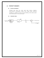
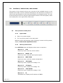
Ver. 1.0en H F C o p t i c a l r e c e i ve r · H R 2 0 4 0 S e r i e s U SER MANU AL Hangzhou Huat ai Opti c T ech. C O., LTD CONTENT 1.0 PRODUCT SUMMARY ........................................................................1 1.1 Product summarize .......................................................................... 1 1.2 Principle frame ................................................................................ 1 2.0 2.1 3.0 CONTROLS, INDICATORS, AND ALARMS ..........................................2 The operation of the panel ................................................................ 2 GUARANTEE AND REPAIR ITEMS .....................................................4 1.0 PRODUCT SUMMARY 1.1 Product summarize HR-2040 high index four return path optic receiver, adopting opto-electronic incorporation module from Fujitsu Japan (receiving sensibility Pr ≤-22dBm) its high receiving sensibility and low noise makes fluent transmission of return path signal. 1.2 Principle frame Page 1 of 4 2.0 CONTROLS, INDICATORS, AND ALARMS This section of the manual will give an overview of the available menus in the HR2040 series optic receiver and their descriptions. All instructions in Section 2.0 refer to the representation of the front panel shown in the diagram below. The user scrolls through the menus using the push bottoms found on the front panel, these are located just to the right of the LCD screen. 2.1 The operation of the panel 2.1.1 Open menu A. Plug in city power supply B. Turn on power switch in the back panel Machine enters self-checking, after checking it enters working status, display “Return Path Optical Receiver”. 2.1.2 Start-up main menu Press STATUS button will display below menu in sequence. Menu # 1 - S/N Read-only menu, tells the serial-number Menu # 2 - INPUT 1~4 Read-only menu, tells the input optical power Menu # 3 - UNIT TEMP Read-only menu, tells the system temperature Menu # 4 - +5V Reads Read-only menu, display the voltage +5V Menu # 5 - -5V Reads Read-only menu, display the voltage -5V Menu # 6 - +24V Reads Read-only menu, display the voltage +24V Menu # 7 - IP Adjustable list, display the IP address of SNMP Page 2 of 4 Menu # 8 - Submask Adjustable list, display the address of net mask Menu # 9 - Gateway Adjustable list, display the gateway address of SNMP Menu # 10 - Trap Addr 1 Adjustable list, display the TRAP1 address of SNMP Menu # 11 - Trap Addr 2 Adjustable list, display the TRAP2 address of SNMP 2.1.3 Menu assistant manual Press key to amend the address menu that should be amended, press STATUS to choose the amend place, push currently value +1, press STATUS to the end of the address to enter into save and exit. For example, amend IP setup menu, IP: 192.168.000.015; if change 5 to 6, use STATUS key to choose the place of 5, then press key to change 5 to 6, then press STATUS to save amended IP:192.168.000.016 Page 3 of 4 3.0 GUARANTEE AND REPAIR ITEMS 1. Each unit is packaged with<Products Qualification>, with the series number provide one-year’s guarantee. 2. Micro-processor software, with the function of monitoring laser status, digital display, trouble alarm, network management etc. pump laser will not be damaged only by man-induced factor. In case of Red lamp sparking (Alarm). Please return for repairing. User should not open the top cover for repair, otherwise, even within guarantee period, maintain and material fee will be charged. 3. Lifelong maintain and upgrade is provided even guarantee period is expired. 4. If component is damaged by man-induced factor, material fee will be charged. Hangzhou Huatai Optic Tech. CO., LTD www.catvworld.net E-mail: [email protected] Page 4 of 4