1
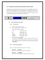
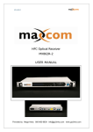
Ver. 1.0en
1 5 5 0 nm D i r e c t Mo d ul a t i on O p t i c a l
Transmi t t e r · HT1 5 0 0 A S e ri e s
U SER MANU AL
Hangzhou Huat ai Opti c T ech. C O., LTD
CONTENT
1.0 PRODUCT SUMMARIZE ......................................................................1
2.0 INSTALLATION .................................................................................1
2.1
Unpacking ........................................................................................ 1
2.2
Transmitter Mounting and Power Connection......................................... 1
2.3
RF connection ................................................................................... 2
2.4
Optic connection ............................................................................... 2
3.0 TRANSMITTER CONTROLS, INDICATORS, AND ALARMS....................4
3.1
The operation of the panel.................................................................. 4
4.0 DESCRIPTION OF STATUS ALARM .....................................................6
5.0 GUARANTEE AND REPAIR ITEMS.......................................................6
1.0 PRODUCT SUMMARIZE
Direct modulation will lead to high laser chirp (Laser's bias current is modulated by
signal and the optical spectrum shifts and shakes). Laser chip will interact with
dispersion effect caused by standard single mode fiber (SMF-28), which will
generate serious distortion in the place of 1550nm. This kind of distortion will
become more serious with the increase of transmission distance, bandwidth and
channel number.
Huatai HT1500A is a 1550nm direct modulation optical transmitter with high index
and AGC function. It adopts high linearity and low chirp DFB laser, built-in
pre-distortion compensation and AGC, APC, ATC closed loop control, which improves
the system index obviously. It can be used in FTTx (≤10Km) of second-grade service
area (sub-headend), also can be used in WDM narrow-band multiplexing and
IP/QAM.
2.0 INSTALLATION
2.1
Unpacking
Inspect the shipping boxes for any obvious damages.
Unpack the unit from all packaging boxes.
Inspect the appearance of the unit for any shipping damages.
Document and inform the shipping company and your local representative, as
seen in section 1.2, of the damages.
Save the shipping boxes and their inserts for any future reshipment for
upgrade or repair.
NOTE: In the event of a reshipment back to the manufacturer, any additional
damages caused by not using the original boxes will be considered
responsibility of the customer.
2.2
Transmitter Mounting and Power Connection
1. Place the unit into a 19-inch wide rack or cabinet. Make sure to leave a
1.75-inch (about 4.5cm) space above and below the unit.
2. According to the design request, HT1500A series 1550nm optic
transmitter can work under 0°C~50°C(32°F~122°F)temperature range. We
recommend 25°C(77°F)environment temperature.
Humidity not bigger than 95%(under non-coagulation condition). If necessary,
the equipment should keep the suitable temperature & humidity in the
Page 1 of 6
restrained scope. We recommend to operating in the environment without
dust.
3. Equipment powered by AC or steady voltage DC. In both of AC & DC, AC is
the chief power supply.
Request of power supply:
AC input
94-245VAC, 50-60Hz
DC input
36-60VDC, floating
Power consumption
Maximum 50W
4. The DC power supply of the equipment must be the SELV supply stipulated
as CAN/CSA C22.2 No.950-95 standard.
5. The machine should have good grounding, grounding resistance<4Ω.
According to the international standard, 220V plug in adopts tri-wire rule, the
middle wire is the grounding wire.
Before connecting circuit, please use big spec (#20AWG and more) electric
wire to connect the grounding screw on the bottom and the grounding frame.
When use DC input power supply, the equipment chassis must be grounding.
2.3
RF connection
Connect the RF cable & the connector on TX rear panel. RF connector is F type
plug. (F-Female/F-male Optional). The resistance is 75Ω.
2.4
Optic connection
1. Considering for protection & safety, all the fiber optic connector need
protect cover in transportation.
2. In order to ensure the insertion loss & return loss, the end-face of fiber
optic connector is polished extremely. Please don’t dirt the pollute the
connector. Even very micro dust will also affect the transmission quality. When
off the fiber optic connector, please put on the protection cover.
3. Clean all fiber patch cords before connecting to the transmitter.
Cleaning Guidelines:
Fiber Patch cord connectors
- Remove the fiber connectors dust cap and wipe the fiber connector tip
with a dry lint-free cloth (such as Kimwipes). Inspect for scratch’s or
debris on connector surface by using a microscopes (ie.100x or 200x).
- If no scratches or debris are found the connector is now clean and ready
for connection. If debris or scratches are found then repeat the fiber patch
cord connector cleaning guidelines.
Fiber Bulkhead connectors
Page 2 of 6
- Compressed air may be used to clean fiber bulkhead connectors. Use
compressed air with at least the following specifications:
- Non-residue, inert gas for precision dust removal
- Ultra-filtered to < 0.2 microns
- Recommended for optical systems
- Using compressed air as listed above, remove the bulkhead dust
cover and hold the can of compressed air about 6 inches from the
connector. After spraying a few short bursts into the bulkhead the
connector is clean and ready for connection.
- If compressed air is not available, the transmitter fiber bulkhead
connector may be cleaned by 2.5 mm cotton swap or connector plate may
be removed to clean the internal fiber patch cords.
CAUTION: Use caution when handling fibers.
Do not exceed fiber manufacturers pulling tension or bend radius specifications
when removing fiber bulkhead connector plate.
- To remove the transmitter optical connector plate, remove the screw on
the far left of the optical plate and remove the screw on the far right of the
optical plate. Do not remove the screws on the optical bulkhead
connector.
- Slowly remove the optical connector plate from the rear panel and
disconnect each fiber connector from the bulkhead mounted on the plate.
- Clean each fiber connector according to section A of the fiber cleaning
guidelines.
4. Make sure the laser key switches on the front panel of the transmitter are
in the OFF position.
5. Connect a fiber patch cord from the output of the transmitter to an optical
power meter.
6. Turn the transmitter laser key switch to the ON position.
7. Using the optical power meter verify the transmitter optical power is within
specification.
8. Turn the transmitter laser key switch to the OFF position.
Page 3 of 6
3.0 TRANSMITTER CONTROLS, INDICATORS, AND ALARMS
This section of the manual will give an overview of the available menus in the
HT1500A series transmitter and their descriptions. All instructions in Section 3.0
refer to the representation f the front panel shown in the diagram below. The user
scrolls through the Tx menus using the push bottoms found on the front panel of the
Tx, these are located just to the right of the LCD screen.
3.1
The operation of the panel
3.1.1
Open menu
A.
Plug in 110V city power supply
B.
Turn on power switch in the rear panel
Front panel display “ KEY OFF”
C.
Laser
Status lamp Red
RF
Status lamp Red
TEMP
Status lamp Green
POWER1
Status lamp Green
POWER2
Status lamp Green
Press laser start-up keyswitch
Front panel shows “KEY ON…”, when the input optic power is in the
normal range, Laser status lamp turns green from red, machine
enters self-checking, after checking it enters working status, display
“ Descriptor”.
3.1.2
Start-up main menu
Press ▲\▼ button will display below menu in sequence.
Menu #1 -
Descriptor
Read-only menu, tells the type of this equipment
Menu #2 -
LD POWER
Read-only menu, displays the optical output power in dBm
Page 4 of 6
Menu #3 -
LD BIAS
Read-only menu, displays laser bias temperature in °C
Menu #4 -
LD TEMP
Read-only menu, displays the laser temperature in °C
Menu #5 Read-only
COOLING/HEATING
menu,
displays
the
amount
of
current
that
the
Thermoelectric Cooler requires to maintain the laser temperature at
nominal 25 °C
Menu #6 -
UNIT TEMP
Read-only menu, tells the system temperature
Menu #7 -
RF LVL
Read-only menu, tells the RF input level
Menu #8 -
RF MODE
Current RF mode, display AGC/Manual
If it appears RF Mode = AGC, while it was in the state of AGC
If it appears RF Mode = Manual, while it was in the state of MGC
Menu #9 -
+5V Monitor
Read only list, display the voltage +5V
Menu #10 - -5V Monitor
Read only list, display the voltage -5V
Menu #11 - +24V Monitor
Read only list, display the voltage +24V
Menu #12 - IP
Adjustable list, display the IP address of SNMP
Menu #13 - S/N
Read-only menu, tells the serial-number
3.1.3
Menu assistant manual
The default control mode is AGC. When the OMI modulation menu displays
RF Mode=AGC, press "SELECT" key and the menu will display RF Mode= .
Then press “▲” or “▼”, the menu will display RF Mode=Manual and the
change from AGC to MGC has been finished. If you want to change the
current control mode back into AGC, press "SELECT" key when the current
menu displays RF Mode=Manual, then the menu will display RF Mode= .
Then press “▲” or “▼”, the change from Manual to AGC will be finished and
the menu will display RF Mode=AGC.
Page 5 of 6
4.0 Description of status alarm
Working status indication (LED), which is near the powers supply switch in the
front panel. When it is green, it is working properly; Red indicates the laser
does not work. Red sparking is alarm.
A.
With 110V power supply, if machine is good, digital panel will display
“KEY OFF”, there is Red light
B.
Turn on with the key, display “KEY OFF” for seconds, laser is also on,
when the input optic power is in the normal range, indication light
turns into Green from Red.
C.
Press ▲\▼ bottom, can display parameters .
D. If any fault listed above occurred, there will be alarm (Red sharking),
Micro-processor will cut down the laser automatically, and digital
panel show the cause of the fault.
In order to protect the laser, there is time-delay function, after turning on with
the key, the laser will start to work after 10 seconds.
5.0 GUARANTEE AND REPAIR ITEMS
1.
Each unit is packaged with<Products Qualification>, with the series number
provide one-year’s guarantee.
2.
Micro-processor software, with the function of monitoring laser status, digital
display, trouble alarm, network management etc. pump laser will not be damaged
only by man-induced factor. In case of Red lamp sparking (Alarm). Please return for
repairing. User should not open the top cover for repair, otherwise, even within
guarantee period, maintain and material fee will be charged.
3.
Lifelong maintain and upgrade is provided even guarantee period is expired.
4.
If component is damaged by man-induced factor, material fee will be charged.
Hangzhou Huatai Optic Tech. CO., LTD
www.catvworld.net
E-mail: [email protected]
Page 6 of 6