1
Application note - DURApulse Drives
AN-GS-014
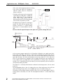
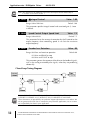
Note: The diagram on the following page shows the output control relationship of
P 10.02, P 10.03 and P 10.04.
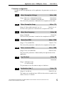
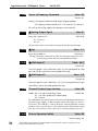
P 10.03
Integral Control
Range: 0.0 to 100.0 sec
Value: 1.00
Default 1.00
This parameter specifies integral control and associated gain (I). Leave
as default.
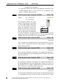
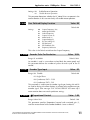
P 10.04
Speed Control Output Speed Limit
Range: 0.0 to 20.0%
Value: 7.5
Default 7.5
This parameter limits the amount of correction by the PI control on the
output frequency when controlling speed. It can limit the maximum
output frequency.
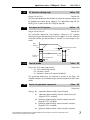
P 10.05
Encoder Loss Detection
Range: 00: Warn and continue operation
Value: 00
Default 00
01: Warn and RAMP to stop
02: Warn and COAST to stop
This parameter governs the response of the drive to the feedback signals,
such as the analog or encoder pulse signals, when they are performing
abnormally.
Closed Loop Tuning Diagram
THIS INFORMATION PROVIDED BY AUTOMATIONDIRECT.COM TECHNICAL
SUPPORT IS SUPPLIED “AS IS”, WITHOUT ANY GUARANTEE OF ANY KIND.
These documents are provided by our technical support department to assist others. We
do not guarantee that the data is suitable for your particular application, nor we assume
any responsibility for them in your application.
12
THIS INFORMATION PROVIDED BY AUTOMATIONDIRECT.COM TECHNICAL SUPPORT IS SUPPLIED “AS IS”,
WITHOUT ANY GUARANTEE OF ANY KIND.