1
N1080B Connectivity
Solutions
(Options H01/H02/H03
HDMI Test Adapters)
User’s Guide
Agilent Technologies
Notices
Safety Notices
© Agilent Technologies, Inc. 2009
CAUTION
Caution denotes a hazard. It calls attention to
a procedure which, if not correctly performed or adhered to, could result in damage
to or destruction of the product. Do not proceed beyond a caution sign until the indicated conditions are fully understood and
met.
No part of this manual may be reproduced in
any form or by any means (including electronic storage and retrieval or translation
into a foreign language) without prior agreement and written consent from Agilent Technologies, Inc. as governed by United States
and international copyright lays.
WARNING
Warning denotes a hazard. It calls attention
to a procedure which, if not correctly performed or adhered to, could result in injury
or loss of life. Do not proceed beyond a
warning sign until the indicated conditions
are fully understood and met.
Manual Part Number
N1080-97000
Edition
December 2009
Printed in Malaysia
Agilent Technologies, Inc.
Digital Signal Analysis Division
1400 Fountaingrove Parkway
Santa Rosa, CA 95403, USA
Warranty
The material contained in this document is
provided “as is,” and is subject to being
changed, without notice, in future editions.
Further, to the maximum extent permitted by
applicable law, Agilent disclaims all warranties, either express or implied, with regard to
this manual and any information contained
herein, including but not limited to the
implied warranties of merchantability and
fitness for a particular purpose. Agilent shall
not be liable for errors or for incidental or
consequential damages in connection with
the furnishing, use, or performance of this
document or of any information contained
herein. Should Agilent and the user have a
separate written agreement with warranty
terms covering the material in this document
that conflict with these terms, the warranty
terms in the separate agreement shall control.
2
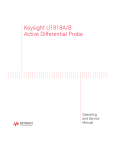
Instrument Markings
This symbol indicates the Environmental Protection Use Period
(EPUP) for the product’s toxic
substances for the China RoHS
requirements.
N1080B Connectivity Solutions
Contents
Contents
Introduction 4
Configuring the N1080B for HDMI 1.3 and HDMI 1.4 Testing
TPA-P and TPA-R Handling Precautions 7
Caution 1. Avoid Torque Forces 8
Caution 2. Avoid Sharp Cable Bends 9
Caution 3. Avoid Cable Tension 10
Caution 4. Connect HDMI Connectors First 11
Caution 5. Carefully Make SMA Connections 11
Recommended Connection Accessories 12
Specifications and Characteristics 15
HDMI Tests and N1080B Options 16
TPA-R and TPA-P Cable Pins 19
TPA Board Assembly 23
General Connector Care 27
Electrostatic Discharge Information 29
Contacting Agilent Technologies 31
6
3
N1080B Connectivity Solutions
Introduction
Introduction
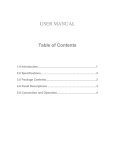
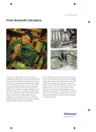
This user’s guide documents the N1080B options H01, H02, and H03; it does not
cover any other versions of the N1080B product. The three options, shown in Figure
1, are tools for testing High Definition Multimedia Interface (HDMI) cables and
devices against the HDMI Compliance Test Specification versions 1.2, 1.3, and 1.4.
When performing tests, always use a static-safe workstation as explained in
“Electrostatic Discharge Information” on page 29.
CAUTION
To avoid damaging the TPA-P and TPA-R cable, use the handling techniques
described in “TPA-P and TPA-R Handling Precautions” on page 7 before making any
connections or configuring a test setup.
The TPA-P and TPA-R cables allow easy access, via SMA connections, for measuring or injecting TMDS or HEAC signals. These cables also connect the HDMI control, DC power, and ground lines to the Option H03 TPA board providing
measurement access to several test points.
Option H01
TPA-P
Option H02
TPA-R
Option H03
TPA Board
Figure 1. HDMI test cables and board
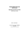
As explained in “TPA Board Assembly” on page 23, the TPA board contains jumpers that easily configure the lines for many test conditions listed in the HDMI Compliance Test Specification. Figure 2 shows how to connect a TPA cable to J1 or J2
on the TPA Board. When making the connection, orientate the cable so that the pin
labels on the cable match the labels on the TPA Board. For example, GND on the
cable connects to pin 1 on J1 or J2.
4
N1080B Connectivity Solutions
Introduction
TPA
Cable
GND
pin 1
HPD
pin 8
TPA
J2
TPA J1
GND HPD
pin 1 pin 8
Figure 2. Connecting a TPA cable to TPA J1 or J2
Accessories
When using Agilent InfiniiMax II series probes, use the N5380A differential SMA
probe head to facilitate connecting to the TPA-R and TPA-P SMA connectors. Refer
to “SMB Cable with N5380A” on page 14 for more information.
Product Inspection
When you receive the product from Agilent, be sure to inspect the shipment:
• Inspect the shipping container and product for damage. Keep the shipping container
and cushioning material until you have inspected the contents of the shipment for
completeness and have checked the product mechanically and electrically.
• Locate the shipping list. Verify that you received all the items that you ordered.
5
N1080B Connectivity Solutions
Configuring the N1080B for HDMI 1.3 and HDMI 1.4 Testing
Configuring the N1080B for HDMI 1.3 and
HDMI 1.4 Testing
The N1080B can be used for both HDMI 1.3 and HDMI 1.4 TMDS / HEAC testing.
To configure the probe for HDMI 1.4 HEAC testing, disconnect the HEAC+ and
HEAC- SMA cables from the TPA Board Connector as shown below. The male side
must then be connected to the 91150AU-EHD HEAC Test Board (refer to the
91150AU-EHD HEAC Test Board data sheet / user’s guide for more information).
HEAC+ and HEAC- SMA cables are disconnected from
the TPA Board Connector
TPA Board
Connector
To configure the probe for HDMI 1.3 testing or HDMI 1.4 TMDS testing, connect
the HEAC+ and HEAC- SMA cables to the TPA Board Connector as shown below
(be sure to match polarity by using the labels/colors on the SMA cables and TPA
Board Connector). The TPA Board Connector is then connected to the N1080B-H03
TPA Board.
HEAC+ and HEAC- SMA cables are connected to the
TPA Board Connector
TPA Board
connector
6
N1080B Connectivity Solutions
TPA-P and TPA-R Handling Precautions
TPA-P and TPA-R Handling Precautions
CAUTION
Avoid making sharp bends in the TPA-P and TPA-R cables or applying twisting or
tension, as described in this section.
This section explains essential handling techniques required to avoid damaging the
TPA-P and TPA-R cables. The eight coaxial cables and bundled HDMI signal cables
are soldered to a printed-circuit board within the adapter’s plastic shell. Improper
handling techniques may damage these internal solder joints. Also, bending the
cables with too small a radius may cause damage. This can occur at any point along
the cable.
In order to achieve optimum performance and to prolong the cable adapter’s life,
observe the handling precautions on the following pages:
• Caution 1. Avoid Torque Forces
8
• Caution 2. Avoid Sharp Cable Bends
• Caution 3. Avoid Cable Tension
9
10
• Caution 4. Connect HDMI Connectors First
• Caution 5. Carefully Make SMA Connections
• Recommended Connection Accessories
11
11
12
7
N1080B Connectivity Solutions
TPA-P and TPA-R Handling Precautions
Caution 1. Avoid Torque Forces
Never apply to an individual coaxial cable or the bundled HDMI signal cables a
torque force that results in a cable twist greater than ±150. Cable twisting occurs
whenever rotation is applied to a cable about its center axis while holding either end
stationary. Twisting can occur when connecting either HDMI or SMA connectors.
For the proper method of making an SMA connection, refer to “Caution 5. Carefully
Make SMA Connections” on page 11.
Figure 3. Example of cable twist
8
N1080B Connectivity Solutions
TPA-P and TPA-R Handling Precautions
Caution 2. Avoid Sharp Cable Bends
Never bend coaxial cables into a radius of 13 mm (½ -inch) or less. Never bend
cables, including the bundled HDMI signal cables, greater than 90. Single or multiple cable bends must be kept within this limit for the single cables or the bundled
HDMI signal cables.
13 mm minimum
bend radius
Do not bend cables
more than 90o
Figure 4. Example of minimum cable bend radius
9
N1080B Connectivity Solutions
TPA-P and TPA-R Handling Precautions
Caution 3. Avoid Cable Tension
Tension is applied to a cable whenever the cable is stressed to reach a test-setup connection or the cable is subjected to the weight of test-setup equipment. Never apply
tension to an individual SMA cable connector that is greater than 2.3 kg (5 lbs.).
Never apply a tension to the bundled HDMI signal cable connector that is greater
than 4.54 kg (10 lbs.). To avoid applying tension, place accessories and equipment
on a table top or surface that can be adjusted vertically to reach the TPA cable. Use
adjustable elevation stands to accurately place your devices.
maximum bundle tension
4.54 kg (10 lbs.)
maximum cable tension
2.3 kg (5 lbs.)
Figure 5. Maximum cable tension
10
N1080B Connectivity Solutions
TPA-P and TPA-R Handling Precautions
Caution 4. Connect HDMI Connectors First
• To avoid twisting, bending, or tension when connecting a TPA-P or TPA-R cable, always connect the HDMI connector before connecting any SMA connectors or the
TPA board connector.
Make sure that all the cables are straight and free of any twisting or bending. First
carefully align the HDMI connectors and then gently push the connectors together
until a detent is felt. If you need to reposition the test setup, first disconnect the
HDMI or DUT connectors.
Caution 5. Carefully Make SMA Connections
To connect TPA SMA connectors, use the following steps:
1 Hold the TPA cable stationary by grasping the cable at the black heat-shrink section
near the cable’s SMA connector.
2 Insert the mating SMA barrel and turn the free spinning SMA nut onto the connector
while avoiding pulling, bending, or twisting the TPA cable.
3 Tighten the nut on the SMA connector by hand. If desired, use a 5 in-lb. torque
wrench to tighten the SMA connection. (Use Agilent torque wrench part number
8710-1582 or equivalent.)
If you need to reposition the test setup, first loosen or disconnect the SMA connections to avoid twisting, bending, or tension.
11
N1080B Connectivity Solutions
TPA-P and TPA-R Handling Precautions
Recommended Connection Accessories
N5380-64701 SMA
Head Support
The Agilent N5380-64701 SMA Head Support is included with the N5380A and
E2695A SMA probe heads to prevent damage to the probe amplifier. It is strongly
recommended that you use the SMA Head Support whenever you are using either of
these probe heads. Below is a drawing showing how to attach the SMA Head Support using two of the four screws provided in the kit (the other two screws are extras
in case you need them in the future). Be sure to plug the probe amplifier into the
SMA head before installing the SMA Head Support. Also, do not attempt to plug or
unplug the SMA head from the probe amplifier while it is in the SMA Head Support
housing.
Figure 6. Attaching the SMA Head Support
SMA Push-on
Adapters
Push-on SMA adapters, available within the industry, can be used to further protect
the SMA connectors. In some cases, these adapters can degrade measurement performance. When disconnecting a connection that has a push-on SMA adapter, grab
the push-on adapter and not the coaxial cable. When selecting a push-on adapter,
choose one with greater than 2 kg of retention force and is verified to be without
power holes in the insertion-loss response.
12
N1080B Connectivity Solutions
TPA-P and TPA-R Handling Precautions
Figure 7. Example of a push-on SMA adapter
Matched SMA Cable At times, you may need to connect the TPA SMA
Pairs
cable pairs to a device such as the Agilent E4887A10x series HDMI cable emulator. Wide spacing of the
SMA connectors can cause stress to the TPA cables.
To relieve the stress, add matched SMA cable pairs
(for example, Agilent 15443A) to the TPA cables
using Agilent 83059B 3.5 mm (f) to 3.5 mm (f)
adapters as shown in Figure 8.
Figure 8. Adding SMA cables to relieve strain
To reduce equipment crowding in your test setups and relieve cable
stress, avoid placing all of the devices, including the device-undertest, on the same side of the equipment setup. You can make a 180
connection by connecting two SMA 90 m-f adapters (Agilent p/n
1250-1249 or equivalent) as shown in Figure 9.
13
N1080B Connectivity Solutions
TPA-P and TPA-R Handling Precautions
SMB Cable with
N5380A
When using the N5380A differential SMA probe head (for Agilent InfiniiMax II
series probes), use an SMB cable with an SMB-to-SMA adapter to connect the dc
bias as shown in Figure 9. The SMB cable is more flexible and therefore preferred
over an SMA cable, in this situation.
BNC (f)-to-SMB (f) cable . . . . . . . . . . . . . . . . . . . . . . . . . . . .Agilent p/n 8120-5007
SMB (m)-to SMA (m) adapter . . . . . . . . . . . . . . . . . . . . . . . .Agilent p/n 1250-2439
Figure 9. SMB and SMA cables and adapters reduce tension and torque
14
N1080B Connectivity Solutions
Specifications and Characteristics
Specifications and Characteristics
Specifications describe warranted performance. Characteristics provide useful, nonwarranted information about the functions and performance of the product. Characteristics are printed in italics.
Table 1. Specifications and Characteristics
Item
Description
Use
Indoor
Cable Length
30 cm (±20 mm) (characteristic)
HDMI Differential Impedance a
Plug
100 ± 15% for each differential TMDS pair
(characteristic)
Receptacle
100 ± 15% for each differential TMDS pair
(characteristic)
Not including HDMI connector region
100 ± 5% for each differential TMDS pair
(characteristic)
Intra-pair skew matching
5 ps (characteristic)
Inter-pair skew matching of differential TMDS pairs
13 ps (characteristic)
Temperature, Operating
0C to +55C (32F to +131F) (characteristic)
Temperature, Storage
–40C to +70C (–40F to +158F) (characteristic)
a. when measured with a minimum 75 ps TDR step.
15
N1080B Connectivity Solutions
HDMI Tests and N1080B Options
HDMI Tests and N1080B Options
Table 2 lists the HDMI tests for which you can use the TPA-R, TPA-P, and TPA
board assemblies. For each test, the recommended number of devices needed is
listed; a blank entry indicates that a device is not needed for that particular test. The
information provided in the table is compatible with the HDMI Compliance Test
Specification versions 1.2 and 1.3.
You must set the positions of several test jumpers on the TPA board assembly in
order to configure the assembly for the tests. Set the position of the test jumpers as
shown in Figure 12 on page 25.
The N1080B is connected to the 81150AU-EHD for HEAC Rx and Tx testing. For
further information on these tests, please consult the 81150AU-EHD HEAC Test
Board Data Sheet / User’s Guide.
16
N1080B Connectivity Solutions
HDMI Tests and N1080B Options
Table 2. HDMI Tests and Associated N1080B Options (1 of 2)
HDMI Test
Quantity
of TPA-P
Cables
Quantity
of TPA-R
Cables
Quantity
of TPA
Board
Cable Assembly Tests
5.3. TMDS Data Eye Diagram
2
5-4. Intra-Pair Skew
2
5-5. Inter-Pair Skew
2
5-6. Far End Crosstalk
2
5-7. Attenuation
2
5-8. Differential Impedance
2
1
Source Tests
7-2. TMDS -VL
1
1
7-3. TMDS - VOFF
1
1
7-4. TMDS - TRISE, TFALL
1
1
7-6. TMDS - Inter-Pair Skew
1
1
7-7. TMDS - Intra-Pair Skew
1
1
7-8. TMDS - Clock Duty Cycle
1
1
7-9. TMDS - Clock Jitter
1
1
7-10. TMDS - Data Eye Diagram
1
1
7-11. +5V Power
1
1
7-12. Hot Plug Detect
1
1
7-13. DDC/CEC Capacitance and Voltage
1
1
7-14. CEC Line Connectivity
1
2
7-15. CEC Line Degradation
1
1
17
N1080B Connectivity Solutions
HDMI Tests and N1080B Options
Table 2. HDMI Tests and Associated N1080B Options (2 of 2)
Quantity
of TPA-P
Cables
HDMI Test
Quantity
of TPA-R
Cables
Quantity
of TPA
Board
Sink Tests
8-4. TMDS - Termination Voltage
1
8-5. TMDS - Min/Max Differential Swing Tolerance
1
1
1
8-6. TMDS - Intra-Pair Skew
1
1
1
8-7. TMDS - Jitter Tolerance
1
1
1
8-8. TMDS - Differential Impedance
1
8-9. DDC/CEC Line Capacitance and Voltage
1
1
8-10. HPD Output Voltage
1
1
8-11. HPD Output Resistance
1
1
8-12. +5V Power Max Current
1
1
8-13. CEC Line Connectivity
1
1
8-14. CEC Line Degradation
1
1
8-15. Character Synchronization
1
1
8-16. Acceptance of All Valid Packet Types
1
1
8-21. Audio Clock Regeneration
1
1
8-22. Audio Sample Packet Jitter
1
1
8-23. Audio Formats
1
1
18
1
N1080B Connectivity Solutions
TPA-R and TPA-P Cable Pins
TPA-R and TPA-P Cable Pins
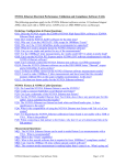
Both TPA-P and TPA-R assemblies provide access to the 4 differential TMDS lanes
(8 total SMA connectors) and access to the control and power supply lines. The
Reserved and Hot Plug lines are broken out with separate cables with SMA
connectors to allow for HEAC testing for HDMI 1.4. Labels clearly mark each cable
or connector. The following figure refers to pin-description tables for each of the
three connector types.
HEAC+ and HEAC- Cables
HDMI Connector
(see Table 5)
TPA Board Connector
(see Table 4)
SMA Connectors
(see Table 3)
Color ID for Differential Pair
Color ID for Data Line Polarity
Figure 10. Cable Connectors
19
N1080B Connectivity Solutions
TPA-R and TPA-P Cable Pins
Table 3. SMA Cable Connectors
Label
Color ID for
Data Line
Polarity
Color ID for
Differential
Pair a
D0+
red
green
D0–
black
D1+
red
D1–
black
D2+
red
D2–
black
CLK+
red
CLK–
black
HEAC+b
red
HEAC–b
black
Description
Differential Data Line 0 (+
line)
Differential Data Line 0 (– line)
blue
Differential Data Line 1 (+
line)
Differential Data Line 1 (– line)
red
Differential Data Line 2 (+
line)
Differential Data Line 2 (– line)
yellow
Differential Clock Line (+ line)
Differential Clock Line (– line)
orange
Differential Data Line (+ line)
Differential Data Line (– line)
a. Corresponds to channel identification color on Agilent Infiniium real-time oscilloscopes.
b. Only applies to HDMI 1.4 HEAC testing
20
N1080B Connectivity Solutions
TPA-R and TPA-P Cable Pins
Table 4. TPA Board Connector
Pin
Control Line Pin Description
1
RF Ground
2
CEC
3
RES (REServed, no connection on device)
4
SCL
5
SDA
6
DDC/CEC Ground
7
+5V
8
HPD (Hot Plug Detect)
21
N1080B Connectivity Solutions
TPA-R and TPA-P Cable Pins
Table 5. HDMI Connector
HDMI
Pin
HDMI Signal
Description
SMA Cable
Labels
Control Line Pin
(to TPA Board)
1
TMDS Data 2+
D2+
—
2
TMDS Data 2 Shield
—
—
3
TMDS Data 2–
D2–
—
4
TMDS Data 1+
D1+
—
5
TMDS Data 2 Shield
—
—
6
TMDS Data 1–
D1–
—
7
TMDS Data 0+
D0+
—
8
TMDS Data 0 Shield
—
—
9
TMDS Data 0–
D0–
—
10
TMDS Clock+
CLK+
—
11
TMDS Clock Shield
—
—
12
TMDS Clock–
CLK–
—
13
CEC
—
7
14
Reserved (no connection on
device)*, HEAC+**
—*, HEAC+**
6
15
SCL
—
5
16
SDA
—
4
17
DDC/CEC Ground*, HEAC
Shield**
—
3
18
+5V
—
2
19
HPD (Hot Plug Detect)*,
HEAC-**
—*, HEAC-**
1
*For testing other than HDMI 1.4 HEAC
**For HDMI 1.4 HEAC testing
22
N1080B Connectivity Solutions
TPA Board Assembly
TPA Board Assembly
The TPA board assembly (low-frequency control board), shown in Figure 11,
includes test jumpers, two TPA-P and TPA-R cable connectors (J1 and J2), and
other components called out in the HDMI tests. It also includes connector J6, so that
you can connect various CEC voltages as specified for the HDMI tests. Likewise,
connector J7 allows you to connect various HPD voltages. Although not called out
in the HDMI specification, an 8-pin DIP socket is provided as a convenience, so that
the design engineer can plug in I2C devices.
Figure 11. TPA Board Assembly Connectors and Jumpers
When performing the tests listed in the HDMI specification, refer to Figure 11 for
line test points as well as DC power supply and ground connections. Refer to Figure
12 for jumper positions matching the listed test connections. These jumpers allow
23
N1080B Connectivity Solutions
TPA Board Assembly
you to quickly and easily configure the test setup for an HDMI test. For example, in
HDMI Test 7-15 CEC Line Degradation, setting jumper J4 connects the CEC line to
the 3.3V DC power via a 27 K resistor.
Figure 13 on page 26 shows the schematic diagram of the TPA board assembly.
Jumpers J3, J4, and J5, shown on the left side of the schematic, configure the TPA
board assembly for the various test conditions. Use jumpers J6 and J7 to supply
CEC and HPD inputs. Sink pull-up resistors R11 and R12 ensure that a strong low is
required for the SDA (serial data) and SCL (serial clock) lines. The combination of
R3/C5 and R4/C6 provide useful filtering for display (TV) environments. Capacitor
C11 is a bypass for the +5V supply line.
24
N1080B Connectivity Solutions
TPA Board Assembly
Figure 12. Test Jumper Settings and Voltage Input Connector Pins
25
N1080B Connectivity Solutions
TPA Board Assembly
Figure 13. TPA Board Assembly Schematic Diagram
26
N1080B Connectivity Solutions
General Connector Care
General Connector Care
Advances in measurement capabilities make connectors and connection techniques
more important than ever. Observing simple precautions can ensure accurate and
reliable measurements.
Handling and storage
• Keep connectors clean
• Extend sleeve or connector nut
• Do not touch mating plane surfaces
• Do not set connectors contact-end down
Visual inspection
• Inspect all connectors carefully before every connection
• Look for metal particles, scratches, and dents
• Do not use damaged connectors
Cleaning
• Clean with compressed air first
• Clean the connector threads
• Do not use abrasives
• Do not get liquid onto the plastic support beads
Making connections
• Align connectors carefully
• Make preliminary connection lightly
• To tighten, turn connector nut only
• Do not apply bending force to connection
• Do not over tighten preliminary connection
• Do not twist or screw in connectors
• Use a torque wrench, and do not tighten past the “break” point of the torque
wrench
3.5 mm and SMA Connectors
Precision 3.5 mm microwave connectors are compatible with an SMA connector
within its specification. Due to the variable quality of the SMA connector, mating
with an SMA can sometimes cause severe damage to the 3.5 mm connector. You can
use SMA connectors if special care is taken when mating the connectors, and all
27
N1080B Connectivity Solutions
General Connector Care
connectors are undamaged and clean. Before each use, check the mechanical dimensions of all connectors with a connector gauge to make sure that the center conductors are positioned correctly.
CAUTION
A male SMA connector pin that is too long can smash or break the delicate fingers
on the precision 3.5 mm female connector.
CAUTION
Some precision 3.5 mm female connector fingers are very tight and can pull the
center pin of their mates out past specifications when the connectors are
disconnected. If such a male pin is inserted into a female connector, it can cause
considerable damage by pushing the female center conductor back too far. Be aware
of this possibility and check all connectors before mating them again.
28
N1080B Connectivity Solutions
Electrostatic Discharge Information
Electrostatic Discharge Information
Electrostatic discharge (ESD) can damage or destroy electronic components. All
work on electronic assemblies should be performed at a static-safe work station. The
following figure shows an example of a static-safe work station using two types of
ESD protection:
• Conductive table-mat and wrist-strap combination.
• Conductive floor-mat and heel-strap combination.
Figure 14. Static-safe Work Station
29
N1080B Connectivity Solutions
Electrostatic Discharge Information
Both types, when used together, provide a significant level of ESD protection. Of
the two, only the table-mat and wrist-strap combination provides adequate ESD protection when used alone. To ensure user safety, the static-safe accessories must provide at least 1 M of isolation from ground. Purchase acceptable ESD accessories
from your local supplier.
WA R N I N G
These techniques for a static-safe work station should not be used when working
on circuitry with a voltage potential greater than 500 volts.
30
N1080B Connectivity Solutions
Contacting Agilent Technologies
Contacting Agilent Technologies
In the unlikely event that the product is defective or incomplete, the section tells you
how to contact Agilent Technologies for technical assistance and how to package
the product for return to an service office. Before returning an instrument for service, you must first call the Call Center at 1 (800) 829-4444.
If the product is still under warranty, it will be repaired under the terms of the warranty. If the product is no longer under warranty, Agilent will notify you of the cost
of the repair after examining the product. When a product is returned to an Agilent
service office, it must be adequately packaged. Please notify the service office
before returning your product.
To contact Agilent Technologies for technical assistance, contact your local Agilent
Call Center.
• In the Americas, call 1 (800) 829-4444
• In other regions, visit http://www.agilent.com/find/assist
Preparing the product for shipping
1 Write a complete reason for returning the product. Include any specific performance
details related to the problem.
2 Pack the product using the original packaging or comparable. Original materials are
available through any Agilent office. Or, follow these recommendations:
• Use a double-walled, corrugated cardboard carton of 159 kg (350 lb.) test strength.
The carton must allow approximately 7 cm (3 inches) on all sides of the product
for packing material and be strong enough to accommodate the weight of the product.
• Surround the product with approximately 7 cm (3 inches) of packing material, to
protect the product and prevent it from moving in the carton. If packing foam is
not available, the best alternative is S.D-240 Air Cap™ from Sealed Air Corporation (Commerce, California 90001). Air Cap looks like a plastic sheet filled with
air bubbles. Use the pink (antistatic) Air Cap™ to reduce static electricity. Wrapping the product several times in this material will protect the product and prevent
it from moving in the carton.
3 Seal the carton with strong nylon adhesive tape.
31
N1080B Connectivity Solutions
Contacting Agilent Technologies
4 Mark the carton “FRAGILE, HANDLE WITH CARE”.
5 Retain copies of all shipping papers.
32
PC32
õö÷ øùú6ûüý
ㇱઙฬ⒓
Part Name
Metal fasteners
Connectors
INTERPOSER/
ANALYZER/
INTERPOSER
/ANALYZER
/OSCILLOSCOPE PROBE
Printed circuit assemblies
Cables
Machined parts
Other parts
Ქኂ‛凝
Ქኂ‛凝ᚗర⚛
Toxic or Hazardous Substances and Elements
卋
Pb
ᳮ
Hg
叏
Cd
ચ卲
卲
ચ
CrVI
ᄙᄽ侶⧶
ᄽ侶⧶
PBB
ᄙᄽੑ⧶ㅘ
ੑ⧶ㅘ
PBDE
}
´
´
´
´
}
}
}
}
}
}
}
}
}
´
}
}
}
´
´
}
}
}
}
}
}
}
}
}
}
}
}
}
}
}
}
O: 6@µÌµÍÎÏD@óµÓÏÔÕ'ÖÓD SJ/TÜÜ363-2006 2â()'<ÖÂãôK?
X: 6@µÌµÍÎÏÐÑD@ÒÓÏÔÕ'Ö×WSJ/TÜÜ363-2006 2â()'<ÖÂã?
O: Indicates that this toxic or hazardous substance contained in all of the homogeneous materials for this part is below the limit requirement in
SJ/T11363-2006.
X: Indicates that this toxic or hazardous substance contained in at least one of the homogeneous materials used for this part is above the limit
requirement in SJ/T11363-2006.
ÉäUåæçè*Æjk'éæ§êëæìUåíîïðñ''ò?
If more than one table is shown above, reference your order or packing list to determine which is applicable to your product.
ÀÁÂ4õ1'ÄÅ;*ÆÇÈ'+,-?
If you have a question about the manufacturing date for your product, ask your Agilent representative
µÉ
\+,-ÇÈ'*Æjk9:ST?
For Agilent contact information, please reference your product manual.
!
"#$%&'()*+,-./0123456789:;<'=>?@=>AB1DEF9:GH
IJK'9:LN'QR*9:GHIJ./D9:STUVW4XY'()GZX?@=>[0\"#$%&0]''^_`gj
kqvwxyzv{81D789:;<|;}~?@789:;<w
{88?@789:;<=>w
'{
8qvw\@'
]J?9:'+,- '¡¢£¤_¥¦2
56§¨©ª+,-
«'¬*®'789:;<¯+,-1°'789:;<±?B²ª+,-
«'¡2378
9:;<=>*1°2'EPUPµ¶'·¸¹*+,-Bª+,-
«''789:;<ºµ
»¼½w¾
¿?
In accordance with the requirements of China’s Administrative Measure on the Control of Pollution Caused by Electronic Information Products (the
“Measure”), Agilent has labeled this product with a number identifying its Environment-Protection Use Period (“EPUP") This number reflects an
estimate of the expected life of the product under the normal use and operating conditions as defined in the product user manual which is
distributed with the product. Use of the number is only for purposes related to the Measure and does not imply or guarantee that the product is
free from defects prior to the EPUP expiration date. No warranties or guarantees are implied by use of the EPUP number. Use of the EPUP
number does not alter any warranties found in, nor affect in any way, the terms and conditions associated with the purchase of this product.
Your Agilent product may contain replaceable assemblies/components (including disk drive, power supply, mouse, display, or battery, which are
not manufactured by Agilent) which have a shorter EPUP number than that which is indicated on the product itself. In cases where the assembly,
component, or part is labeled with an EPUP which differs from the one indicated by Agilent, the EPUP on the assemblies/component or part takes
precedence. Agilent makes no claims concerning, and takes no responsibility for the EPUP numbers reflected on goods which are not
manufactured by Agilent.
Revision: G
Agilent Technologies, Printed in the Malaysia December 2009
Manual Part Number: N1080-97000
*N1080-97000*