1
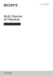
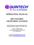
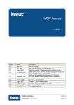
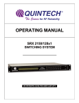
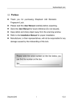
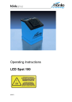
Implementing 1+1 RF Redundancy with the SMD-989
Application Note
December 2011
Page 1 (10)
www.sencore.com | 1.605.978.4600
Revision 1.0
Implementing 1+1 RF Redundancy with the SMD-989 – © 2011 Sencore, Inc. – Application Note
Copyright
© 2011 Sencore, Inc. All rights reserved.
3200 Sencore Drive, Sioux Falls, SD USA
www.sencore.com
This publication contains confidential, proprietary, and trade secret information. No part of this document may be copied,
photocopied, reproduced, translated, or reduced to any machine-readable or electronic format without prior written
permission from Sencore. Information in this document is subject to change without notice and Sencore Inc. assumes no
responsibility or liability for any errors or inaccuracies. Sencore, Sencore Inc, and the Sencore logo are trademarks or
registered trademarks in the United States and other countries. All other products or services mentioned in this document
are identified by the trademarks, service marks, or product names as designated by the companies who market those
products. Inquiries should be made directly to those companies. This document may also have links to third-party web
pages that are beyond the control of Sencore. The presence of such links does not imply that Sencore endorses or
recommends the content on those pages. Sencore acknowledges the use of third-party open source software and licenses
in some Sencore products. This freely available source code can be obtained by contacting Sencore Inc.
About Sencore
Sencore is an engineering leader in the development of high-quality signal transmission solutions for the broadcast, cable,
satellite, IPTV, and telecommunications markets. The company's world-class portfolio includes video delivery products,
system monitoring and analysis solutions, and test and measurement equipment, all designed to support system
interoperability and backed by best-in-class customer support. Sencore products meet the rapidly changing needs of
modern media by ensuring the efficient delivery of high-quality video from the source to the home. More information about
Sencore is available at the company’s website, www.sencore.com.
All trademarks and registered trademarks mentioned herein are the property of their respective owners.
Page 2 (10)
Revision 1.0
Implementing 1+1 RF Redundancy with the SMD-989 – © 2011 Sencore, Inc. – Application Note
Table of Contents
1
Introduction ......................................................................................................................................................... 4
2
Redundancy System Configuration .................................................................................................................... 5
2.1
Redundancy System Overview ............................................................................................................. 5
2.2
Specific Considerations when Configuring an RF Redundancy System ............................................ 5
3
Failover Triggers .................................................................................................................................................. 7
3.1
Failover on Power Loss ......................................................................................................................... 7
3.2
Failover on Input Status or Unit Errors ................................................................................................ 7
4
Example System Configuration .......................................................................................................................... 8
5
Qualified Equipment List .................................................................................................................................... 9
Page 3 (10)
Revision 1.0
Implementing 1+1 RF Redundancy with the SMD-989 – © 2011 Sencore, Inc. – Application Note
1 Introduction
Satellite modulators sit at a critical point in the delivery chain for a video distributor. When a satellite link
goes down, thousands, or even millions, of customers can lose their video feed. Telephones from the
provider's customer service center all the way up to the network operations center will begin ringing, and a
mad scramble to diagnose and repair the issue will kick off in no time.
While Sencore designs its modulators to operate reliably, consistently, and free of issues for years, many
distributors prefer to build an extra layer of reliability into their broadcast systems through the use of
redundant equipment. This application note outlines an example of a redundant system installation using
the Sencore SMD 989 modulator. The particular redundancy scenario illustrated in this document
operates at the RF (L-Band) layer of the distribution system, and involves two redundant, identically
configured SMD 989 modulators. As such, it is referred to as "1+1 RF Redundancy."
Sencore does not currently manufacture RF redundancy switches. Sencore's focus thus far has been on
providing modulators with the best possible signal quality, most useful feature set for video distributors,
and quickest, most straightforward set-up and operation. Sencore has, however, qualified several thirdparty RF redundancy switches for use with our DVB-S/S2 modulator.
Redundancy switch design may seem outwardly simple, but the switch's positioning as a single point of
failure in the broadcast chain requires that it be designed with a high degree of reliability and robustness
in mind. The switches discussed in this system embody these qualities, and have been qualified as
compatible with the SMD 989. In addition, they provide the proper interfaces for maximum system
redundancy when coupled with the SMD 989.
Page 4 (10)
Revision 1.0
Implementing 1+1 RF Redundancy with the SMD-989 – © 2011 Sencore, Inc. – Application Note
2 Redundancy System Configuration
2.1 Redundancy System Overview
A basic overview of a 1+1 RF redundancy system is shown in Fig. 2-1 below. It focuses on three pieces:
two modulators and a redundancy switch. Many redundant broadcast systems have additional
redundancy built all the way "up the chain" to the video encoder. However, as the focus of this paper is on
redundancy in satellite modulation, those pieces are not shown in the figure.
Transport Stream
Input (ASI or IP)
SMD 989
DVB-S/S2 Modulator
(Primary)
Relay Closure Signal
(Optional)
L-Band RF Signal
Transport Stream
Input (ASI or IP)
Third Party RF
Redundancy Switch
L-Band RF Signal
SMD 989
DVB-S/S2 Modulator
(Backup)
Fig. 2-1: Diagram of 1+1 RF Redundancy System with Two Modulators and Redundancy Switch
2.2 Specific Considerations when Configuring an RF Redundancy System
There are several important considerations to note when configuring and selecting components for a
system such as this one.
Modulator Input: The input feeds to the two modulators should be identical. In the case of ASI video
inputs, the two inputs are typically fed from identical links of a fully redundant system, or generated by
a distribution amplifier or signal router. In the case of MPEG-TS over IP, the two modulators should be
subscribed to identical multicasts, and may possibly be fed by separate network segments.
Modulator Configuration: In order for the failover experience between the two units to be as seamless
as possible, the two modulators should be identically configured with regard to modulation
parameters. One exception to truly identical modulator configuration may be the IP addresses for the
units' Ethernet interfaces. If the units are connected to the same network, these IP addresses will be
different.
Unit Profiles: The Sencore Unit Profile Feature can be used to achieve identical unit configuration.
Profiles are human-readable text files which can be downloaded from an SMD, and contain all settings
for the unit. The profile can be applied to the backup unit to ensure identical modulator setup. Also, if
a unit should need to be physically replaced, the profile can be applied to that replacement unit.
Note: Sencore profiles exclude unit IP addresses by default, and can be applied safely to two units on
the same network.
Redundancy Switch Connection: The redundancy switches suggested in this document have support
for the full range of L-Band signals. However, some switches support only a limited frequency band,
so it is important to check the supported frequency range when considering a switch.
Additionally, there are a few other important items to note with regard to the modulator output.
1. Most redundancy switches do not support pass through of BUC/DC/LNB power. If power on the LBand output is required, it may be necessary to inject that power after the redundancy switch.
2. The same consideration applies to other signals which may be coupled onto the L-Band cable,
such as a 10MHz reference clock.
Page 5 (10)
Revision 1.0
Implementing 1+1 RF Redundancy with the SMD-989 – © 2011 Sencore, Inc. – Application Note
3. As always when connecting RF transmission components, the L-Band cable should be impedance
matched. This may require a matching pad between the modulator and the switch. The SMD
989's L-Band output is a 50 Ohm SMA connector.
L-Band Failover: The redundancy switches in this document will monitor the L-band input from the
modulator and trigger a failover to the backup input signal if that input disappears. An overview of this
behavior can be found in the Failover Triggers section.
Relay Output: The diagram above illustrates an optional relay output connection between the
modulators and the redundancy switch. This connection can be used to control switch failover. More
information on this topic can be found in the Failover Triggers section.
Redundancy Switch Output: The L-band output from the redundancy switch is the key, critical link in
the redundancy system. As such, it should be situated as close to the transmitter as practical. It may
be advantageous to site the entire modulation redundancy system in the transmitter facility.
As every installation is different, additional, specific considerations may apply in a given use case.
Sencore Application Engineers are happy to discuss additional details, and can be reached at
(605) 339-0100.
Page 6 (10)
Revision 1.0
Implementing 1+1 RF Redundancy with the SMD-989 – © 2011 Sencore, Inc. – Application Note
3 Failover Triggers
3.1 Failover on Power Loss
All of the redundancy switches recommended in this document support failover on loss of signal. If a cable
becomes disconnected, an upstream portion of the system loses power, or a power supply fails, this will be
sufficient to detect input loss and trigger failover to the backup modulation chain. Some distributors may
prefer to have a more comprehensive set of system conditions trigger redundancy switching.
3.2 Failover on Input Status or Unit Errors
The SMD 989 provides internal monitoring of several key signal characteristics and unit status items.
Each of these can be selected as trigger conditions to activate the SMD 989's relay output. If this output is
connected to the redundancy switch's control input, these conditions can be used to trigger failover to the
backup chain. Fig. 3-1 shows an example of the SMD 989's system condition configuration dialog.
Fig. 3-1: SMD 989 System Condition and Relay Configuration
For a full list of conditions available to trigger failover, consult the SMD 989 user's manual.
Page 7 (10)
Revision 1.0
Implementing 1+1 RF Redundancy with the SMD-989 – © 2011 Sencore, Inc. – Application Note
4 Example System Configuration
An example wiring diagram of two SMD 989 modulators in conjunction with a Quintech RFS2150
redundancy switch is shown below in Fig. 4-1.
SMD 989 (Primary)
Modulated
Output
(L-Band)
SMD 989 (Backup)
Modulated
Output
(L-Band)
50/75 Ω
Matching Pad
50/75 Ω
Matching Pad
Connect Relay 1: Common (Pin 2 on SMD)
to GND Pin on RFS 2150
Connect Relay 1: Normally Open (Pin 3 on SMD)
to CTL Pin on RFS 2150
RFS 2150
OUTPUT
PRIMARY
INPUT
SECONDARY
INPUT
|
CTL
|
GND
L-Band Out
To Transmitter
Fig. 4-1: Example Installation with Redundancy Switch
When the Primary SMD 989 experiences a power failure, input alarm, or other pre-configured condition
(see Section 3), the normally-open relay will close. This will connect the CTL and GND pins on the Quintech
redundancy switch, and automatically trigger a switchover to the backup input.
Additionally, when one of the modulators loses power, the RFS 2150 will detect loss of signal on its input
port and automatically fail over.
Note that the SMD 989’s contact closure ports are driven by “Form C” relays, and can be connected in
either the “normally open” or “normally closed” position. The pinout of the SMD 989 alarm connector is
shown in Fig. 4-2 below.
Pin 1: Relay 1
Normal Closed
Pin 3: Relay 1
Normal Open
Pin 6: Relay 2
Normal Closed
Pin 5: Relay 2
Normal Open
Pin 2: Relay 1
Common
Pin 4: Relay 2
Common
Fig. 4-2: SMD 989 DB-9 “Alarm” Connector Pinout
Page 8 (10)
Revision 1.0
Implementing 1+1 RF Redundancy with the SMD-989 – © 2011 Sencore, Inc. – Application Note
5 Qualified Equipment List
The following redundancy switches have been evaluated in-house by Sencore and are qualified for use
with the SMD 989
Vendor
ETL Systems
Quintech
Newtec
Table 5-1: Qualified Redundancy Switches
Model
Power Detect Failover
23116-S5S5
Yes
RFS2150
Yes
AZ210
Yes
Relay Input Triggers
Yes
Yes
Yes
Sencore is actively testing the SMD 989 with additional components, so this list should grow over time. If
there is a specific redundancy you would like Sencore to test, please contact us directly.
Sencore currently does not resell these solutions. However, Sencore can assist with contacting one of
these companies and configuring the redundancy switch if desired. Please contact your account manager
at (605)-339-0100 for more information.
Page 9 (10)
Revision 1.0
Sencore Inc.
3200 Sencore Drive
Sioux Falls, SD 57107 USA
www.sencore.com
Page 10 (10)
Copyright © 2011, Sencore Inc.
1.605.978.4600