1
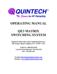
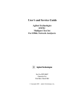
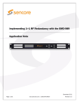
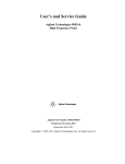
OPERATING MANUAL SRX 2150/128x1 SWITCHING SYSTEM US PATENTS 4,935,709 AND 5,481,073 This page intentionally left blank Quintech Electronics and Communications Inc. SRX Series Switching System PAGE 1.0 INTRODUCTION............................................................................................................................1 2.0 MODULES .......................................................................................................................................2 3.0 INSTALLATION.............................................................................................................................3 RF Connections..................................................................................................................................3 Control Connections ..........................................................................................................................3 Power Connections ............................................................................................................................4 4.0 OPERATION ...................................................................................................................................5 4.1 Monitor and Control....................................................................................................................5 4.1.1 Changing a Crosspoint ......................................................................................................6 4.2 Configuring System Options .......................................................................................................7 4.2.1 Configuring Controller Parameters ...................................................................................7 4.2.1.1 Setting Up the System ..........................................................................................8 Matrix Size ...........................................................................................................8 Model....................................................................................................................9 Module Size..........................................................................................................9 4.2.1.2 Upgrading the SRX’s Firmware .......................................................................10 4.2.2 Configuring Interface Options.........................................................................................10 4.2.2.1 Serial Configuration ...........................................................................................10 Address ...............................................................................................................11 Mode...................................................................................................................12 Terminate RS485................................................................................................12 Quintech Electronics and Communications Inc. SRX Series Switching System 4.2.2.2 Ethernet Configuration .......................................................................................13 Static IP Configuration .......................................................................................13 DHCP .................................................................................................................14 QEC Port # .........................................................................................................14 Password.............................................................................................................15 4.3 Ethernet Control ........................................................................................................................15 4.4 Serial Port Control.....................................................................................................................16 5.0 TROUBLESHOOTING ................................................................................................................17 Quintech Electronics and Communications Inc. SRX Series Switching System Appendix A – Technical Specifications x Electrical x Mechanical x Protocol Appendix B – Test Procedure Appendix C – Performance Plots Appendix D – Setting the SRX Expansion Module Address Switches This page intentionally left blank Quintech Electronics and Communications Inc. SRX Series Switching System Rev. A 1.0 INTRODUCTION Thank you for purchasing an SRX Expandable Routing Switch. Quintech’s SRX series switches are based on the same technology as our popular SRM Series Modular Programmable RF Switches. They were developed to address the increasing need for expandable RF switching in telecommunication network signal processing centers and are equally suitable for audio/video, baseband, data, IF, and RF switching requirements. The SRX is perfect for centralized test and measurement applications in networks that are monitoring large numbers of RF signals. Each SRX system is compatible with most monitoring and control systems and can be expanded in 16x1 modules up to a maximum capacity of 128x1. Control of the SRX occurs from a front panel keypad or remotely via computer (serial or TCP/IP). The excellent RF performance of the SRX is achieved through proprietary technology developed by QEC. Each system is supplied with a control unit. From this unit, an operator may make RF signal routing changes or check to see the routes currently defined. The control unit is also supplied with serial (RS-232 and RS-422/485) and Ethernet (10BaseT TCP/IP) control ports to allow remote control of the SRX system. This operating manual attempts to familiarize you with the different capabilities and features of SRX systems. Please read all instructions before installing or operating. 1 Quintech Electronics and Communications Inc. SRX Series Switching System Rev. A 2.0 MODULES Two types of modules are used to configure an SRX system: an MCP 128 (8x1) controller and a 16x1 switching module. Every SRX system is comprised of one controller and 1 or more switching modules. A minimal SRX switching system consists of a single controller and one switching module. The MCP 128 controller provides master control capability via the front panel keypad/LCD display or computer interface (serial or TCP/IP). The unit receives commands from the keypad or computer and controls the individual switching modules. From this unit, an operator can make routing changes or check to see the paths currently configured. Q-SWITCH MCP 2150 SERIES SIGNAL ROUTING SWITCH ETHERNET C O N T R O L I N C O N T R O L O U T 1 2 3 4 1 2 3 4 5 F1 F2 -5V 6 7 8 9 0 F3 F4 +5V 5 6 7 8 OUTPUT INPUTS MCP 128 (8x1) Controller If no 16x1 switching modules are added to the SRX system, the controller can be used as a standalone 8x1 switching module. The SRX Switching Module is a 16x1 unit that utilizes solid state switching elements to provide seamless switching speeds (nanoseconds). Up to eight switching modules may be combined in a single SRX system. The total number of switching modules required for a system is equal to the total number of system inputs divided by 16. Every switching module is equipped with two inter-module serial ports (“CONTROL-IN” and “CONTROL-OUT”) that are used for communication with other SRX modules. 2 Quintech Electronics and Communications Inc. SRX Series Switching System Rev. A -5V +5V ELECTRONICS AND COMMUNICATIONS INC. C O N T R O L I N C O N T R O L O U T 1 2 3 4 5 6 7 8 9 10 11 12 13 14 15 16 OUTPUT INPUTS 16x1 Switching Module 3.0 INSTALLATION The SRX is very easy to install. Each module is 1RU (1.75”) in height and is easily installed in any standard rack, using four screws. RF Connections All RF connections are made by connecting source(s) to the input(s) and destination(s) to the output(s). When connecting, be sure that the pin at the center of the RF connector is properly inserted into the F connector on the units. A bent pin will not pass the RF signal correctly. NOTE: All inputs and outputs are DC blocked. You cannot send power through the SRX to power other devices. Control Connections Before powering up the units, make sure all of the control cables are properly installed. All SRX modules should be daisy-chained together, with the controller unit occupying the first position in the chain. Connect the CONTROL OUT port of the controller to the CONTROL IN port of the first 16x1 module in the chain. The CONTROL OUT port of that module connects to the CONTROL IN port of the next 16x1 module, etc. The last module in the chain will have an unused 9-pin connector labeled CONTROL OUT. Note that the maximum control cable length that can exist between SRX modules is 6 feet. 3 Quintech Electronics and Communications Inc. SRX Series Switching System Rev. A If you are using a computer to control the SRX, you can use a direct serial connection or a 10BaseT Ethernet connection. For serial control, connect a serial cable (RS-232 or RS-422/485) from the computer to the 9-pin SERIAL port on the rear panel of the controller module. The connector is shared for both RS-232 and RS-422/485. No NULL MODEM or crossover cable is needed when connecting an RS-232 cable. For Ethernet connections, connect the controller to a network port or router via the Ethernet port using a standard cable. You can also connect directly to the computer’s network port, but this requires a crossover cable. Power Connections To power up each unit, connect it to an appropriate AC power source. Most units will be equipped with a 2-amp slo-blo AC fuse. The AC/DC power supplies used in the SRX are extremely reliable, and provide short circuit protection. Before powering up the controller module, power up all other SRX modules first. 4 Quintech Electronics and Communications Inc. SRX Series Switching System Rev. A 4.0 OPERATION The SRX Series Matrix Switching System can be controlled locally via the front panel keypad/LCD screen or remotely through the serial port or Ethernet port on the rear panel using the software provided with all standard SRX modules. If desired, all three methods can be used simultaneously. Firmware updates can be downloaded via the Serial and Ethernet ports. The front panel keypad and LCD screen are used to set various operating parameters and to monitor and control switch settings. The main menu has two choices: 1. Monitor & Control and 2. System Options. 1. Monitor & Control 2. System Options Main Menu 4.1 Monitor and Control Press 1 to choose local monitor and control. The current switch settings will be displayed as illustrated below. Status Port np 1 F1=Change F4=Exit Monitor & Control Screen 5 Quintech Electronics and Communications Inc. SRX Series Switching System Rev. A To view the status of an output or input channel, type in the output/input number or use the scroll arrows to scroll up or down respectively. One, two, or three digits may be typed. For example, Output 1 may be represented as 1, 01, or 001. The number will be entered automatically about 1 second after no more digits are entered. Press F4 to exit back to the main menu or F1 to change the input connected to the currently displayed output. 4.1.1 Changing a Crosspoint To change the current input (or output) port, press F1 to enter the Change Port Screen. The menu heading will revert to “Change” and the cursor will move to the Port field. Change np F1=Enter Port F4=Exit 4 Change Port Screen Select the new input (or output) port by either scrolling or by typing in the desired port number. Press F1 to enter the change. To return to the main menu without making any changes, press F4. 6 Quintech Electronics and Communications Inc. SRX Series Switching System 4.2 Rev. A Configuring System Options From the Main Menu, press 2 to access the System Options Menu. The System Options Menu enables you to set and modify basic configuration parameters. It also enables you to configure the SRX’s communications interface. 1. Configuration 2. Interface Options F4=Exit System Options Menu Pressing 1 will display the Configuration Menu. To prevent unintentional changes to the SRX’s configuration, the Configuration Menu is password protected. You must enter the correct 3-digit password and press F1 before access to the Configuration Menu is granted. The code for SRX series units is 732. Pressing 2 will display the Interface Options Menu. NOTE: Do not alter any of the configuration menu items unless directed by Quintech. 4.2.1 Configuring Controller Parameters The Configuration Menu enables you to set various controller configuration parameters or upgrade the unit’s firmware via the serial port. 1. System Setup 2. Load Firmware F4=Exit Configuration Menu 7 Quintech Electronics and Communications Inc. SRX Series Switching System 4.2.1.1 Rev. A Setting Up the System The system configuration parameters consist of the SRX size and model number. The configuration settings are set at the factory and should not be changed unless directed by Quintech. Altering the configuration can prevent the SRX from operating correctly. 1. Matrix Size 3. Module Sizes 2. Model F4=Exit System Setup Menu Matrix Size The Matrix Size screen allows the specified size of the SRX to be changed. Enter a number between 8 and 128 to indicate the number of SRX input (or output) ports. Press F1 to enter the change. To return to the previous menu without making any changes, press F4. If the MCP is being used as a standalone switch with no expansion modules, this parameter is set to the number of input ports on the MCP. # of Ports: 16 F1=Enter F4=Exit Typical Matrix Size Screen 8 Quintech Electronics and Communications Inc. SRX Series Switching System Rev. A Model The model number is included as part of the system’s firmware identification in accordance with the protocol outlined in Appendix A. The control system is not affected by the model number. System expansion requires no change of the model number. Model: 2150 F1=Enter F4=Exit Typical Model Number Screen Module Size Configuring the SRR module size involves specifying the number of inputs per SRX (option 1) and the number of input rows/SRO (option 2). 1. SRR Module Size 2. SRO Module Size F4=Exit Module Size Menu The SRR module size must be set to the number of inputs on each SRX module. The SRO module size must be set to the number of inputs on the MCP. The factory default is 8. The default is 16 for a system with 16x1 expansion modules. If the MCP is used as a standalone switch with no expansion modules, the factory default is 1. 9 Quintech Electronics and Communications Inc. SRX Series Switching System 4.2.1.2 Rev. A Upgrading the SRX’s Firmware Pressing 2 from the Configuration Menu displays the Load Firmware Screen. The Load Firmware Screen enables you to upgrade the internal firmware level of the SRX unit. Pressing F1 will put the controller in a special firmware download mode. The new firmware can then be downloaded via the serial port. This process requires the Rabbit Field Utility (RFU) v 2.25 to be executed on the PC from which the firmware is being transferred. Once the RFU shows that the process is complete, the SRX must be power cycled to return to normal operation. Press F1 to set Firmware download “Control In” as F4=Exit Load Firmware Screen 4.2.2 Configuring Interface Options The Interface Options Menu allows you to configure either serial communication or Ethernet settings. 1. Serial 2. Ethernet F4=Exit Interface Options Menu 10 Quintech Electronics and Communications Inc. SRX Series Switching System Rev. A 4.2.2.1 Serial Configuration Whenever “Serial” is selected, you will be able to configure both the address of the SRX and the type of serial interface (RS-232, RS-485, or RS-422). 1. Address 3. Terminate RS485 2. Mode F4=Exit Address Menu Address The Address Screen allows you to set a 2-byte hexadecimal address for the switch. Addresses can be set from 00 to FF hexadecimal. The unit only responds to commands sent over the serial bus that contain a matching address. The only exception is the address “FF” which serves as the “broadcast” address. Any and all units will respond to a command containing FF as the address, regardless of its current address. For this reason, FF should not normally be used as a unit address. To change the address, use the up and down scroll arrows until the desired address is displayed, then press F1 to select the new address. The specified address is used when sending commands to the control unit from a computer. Current Address 0 New Address np 1A F1=Enter F4=Exit Address Screen 11 Quintech Electronics and Communications Inc. SRX Series Switching System Rev. A Mode The Mode Screen enables you to specify whether an RS-232, RS-485, or RS-422 serial interface will be used to control the serial communications. Mode: RS232 2=RS485 1=RS232 F4=Exit 3=RS422 Mode Screen Terminate RS485 The Terminate RS485 Screen allows you to enable or disable termination on the serial port. Only one device at the end of an RS485 cable should have termination enabled. 1. Control In: Off F1=On F2=Off 2. Remote Ports: Off F4=Exit Terminate RS485 Screen 12 Quintech Electronics and Communications Inc. SRX Series Switching System Rev. A 4.2.2.2 Etheret Configuration The Ethernet configuration screen controls the static IP configuration for Telnet (port 23) and the auxiliary QEC port. The QEC port allows you to send STX/ETX formatted packets to the SRX. Whenever “Ethernet” is selected in the Interface Options menu, you will be able to set the IP configuration (option 1), enable/disable the DHCP server (option 2), and configure the Ethernet port (option 3). You will also be able to reset the access password (option 3). 1. IP Configuration 3. QEC Port 2. DHCP On/Off F4=Exit Static IP Configuration The IP Configuration screen allows you to set the IP address, network, and default gateway address for the SRX. Contact your network administrator for the correct values to use for these parameters. Note that if DHCP is on, the settings obtained from the DHCP server will override the static IP configuration. IP :192.168.000.249 GW :192.168.000.001 Msk:255.255.255.000 F1=Enter F4=Exit IP Configuration Screen 13 Quintech Electronics and Communications Inc. SRX Series Switching System Rev. A DHCP The DHCP Screen enables you to enable or disable the use of a DHCP server for obtaining IP address information. When set to ON, the IP address of the SRX is dynamically assigned by the DHCP server. Note that the IP address assigned in this manner will override any IP address that may have been specified via the IP Configuration Screen. When set to OFF, the static IP address that is specified in the IP Configuration Screen will be used. 1.DHCP :Off F1=On F2=Off F4=Exit DHCP Screen QEC Port # The Port screen allows you to configure the port number for the QEC port access. Contact your network administrator for the correct values to use for this parameter. Use the scroll keys to scroll the port number up or down until the desired port number is displayed. Press F4 to exit or F1 to change the port number. Current Port New Port np 9100 F1=Enter 9100 F4=Exit Port Screen 14 Quintech Electronics and Communications Inc. SRX Series Switching System Rev. A Password The Password Screen enables you to reset the QEC port access password to the Quintechspecified default. Press F4 to exit or F1 to reset the password. Reset password F1=Enter to “Quintech” F4=Exit Password Screen 4.3 Ethernet Control The SRX has a 10BaseT Ethernet port and supports TCP/IP. All commands are sent to the configured IP address and port. The command protocol for controlling the switch is provided in Appendix A The same command protocol is used for control over the Ethernet QEC port and the serial port. Since the same command formats are used, the command packet will contain a serial address. This address must match the serial address of the SRX or the packet will be rejected, even though the address is unnecessary when the command is sent over TCP/IP. To avoid any problems, commands are sent over TCP/IP should use the broadcast address “FF” hexadecimal. Please note that SNMP is not currently implemented. Connecting the SRX via Telnet opens a Telnet console window. From the console window, you can change the configuration or issue commands. The commands issued through the Telnet window do not use a serial address or STX/ETX packet formatting. 15 Quintech Electronics and Communications Inc. SRX Series Switching System 4.4 Rev. A Serial Port Control The SRX has a standard DB-9 serial input connector on the back panel. This connector is shared for both RS-232 and RS-422/485 interfaces. The serial port parameters are fixed at 9600 baud, 8 data bits, no parity, and 1 stop bit (8N1). No NULL MODEM or crossover cable is required on this port. The command protocol for controlling the switch is provided in Appendix A. The RS-232 pin out is as follows: The RS-422/485 pin out is as follows: 1 – Not Used 2 – TXD (transmit data) 3 – RXD (receive data) 4 – Not Used 5 – GND (signal ground) 6 – Not Used 7 – Not Used 8 – Not Used 9 – Not Used 1 – NC 2 – NC 3 – Non-Inverting Transmit 4 – Non-Inverting Transmit 5 – NC 6 – Inverting Transmit 7 – NC 8 – NC 9 – Inverting Receive 2 11 6 33 77 55 44 88 99 Male D-9 Connector 16 Quintech Electronics and Communications Inc. SRX Series Switching System Rev. A 5.0 Troubleshooting This section has been written to help eliminate operator error. It does not describe how to repair damaged equipment. The control connections are properly connected, yet the system is not communicating. It is possible that the system needs to be biased or terminated. Refer to Appendix A. The front panel LED/LCD is not lit. This indicates the unit is not receiving power. Check to see if the power switch is in ON. Make sure that the AC cables are properly connected. Check the fuse located just above the power cord. Verify that the AC source is available. The power supply LED is on but the LCD is not. Contact Quintech for service. No signal is passing at all. The connection is shown as being made but no switch occurred. First, be certain that all coaxial cables are properly connected, and that all control cables are connected and in good working conditioning. Type in the desired path again. Type in a different path to verify that the units are switching. If the units are switching, verify that the signal you requested is actually there (the SRX system is DC blocked and will not allow receivers to power LNBs). It is useful to monitor the system with some type of analyzer. Make sure that the SRX routing is properly configured. The SRX will only switch up to the set maximum size. If the controller unit is configured to utilize a larger size than is physically available, it will show routing crosspoints that are not physically available. The unit does not remember the previous switch settings/switch size after power has been removed and restored. Contact Quintech for service. 17 Quintech Electronics and Communications Inc. SRX Series Switching System Rev. A The SRX will not respond to protocol commands on the Serial Port. Make sure that the address in the commands being sent matches the serial address set for the SRX. Check that the serial interface mode (RS-232 or RS-485) is correct and that the serial cable from the computer is connected to the CONTROL IN DB-9 connector port on the back panel. If you are using RS-232, make sure that no null modem is being used in the control path. The SRX will not respond to protocol commands on the Ethernet QEC Port. Make sure that the serial address in the commands being sent is either set as “FF” or matches the serial address set for the SRX. Make sure that the SRX IP address matches the target address used by the control computer. Make sure that the control computer is sending the commands to port 9100. Make sure that the netmask and/or gateway are correctly set for your network. If the SRX is connected directly to the network port of another computer, make sure that a crossover cable is being used. If the SRX is connected to a router, make sure that a standard cable is being used, that the router detects the connection to the SRX, and that the router is connected to the same network as the control computer. The signal is passing at a low level. Using appropriate equipment, check the signal level. If it is below specifications, contact the factory. The SRX will not connect using Telnet. Make sure that another Telnet session is not currently open. Only one Telnet session at a time is allowed. 18 Quintech Electronics and Communications Inc. SRX Series Switching System Rev. A I am a qualified technician and would like to try to fix a problem myself. A warranty covers all units. QEC, or a representative of QEC, should make the required repairs. Removing any part of the chassis will void the warranty. Additionally, attempting to repair a unit could be dangerous. There is a lot of crosstalk between the signals. It may be necessary to “balance” your signal levels. Leveling the signals (attenuating stronger signals, amplifying weaker signals) ensures that all signals will be passing at approximately the same level. For additional information or technical support please contact QEC. Toll Free: (800) 839-3658 Fax: (724) 349-1412 Email: [email protected] 19 This page intentionally left blank I N C O N T R O L O U T C O N T R O L O U T C O N T R O L 1 2 3 4 6 2 7 3 5 9 INPUTS 8 INPUTS 4 7 6 10 6 2 1 11 7 8 3 8 12 9 4 THE REPRODUCTION, USE OR DISCLOSURE, IN WHOLE OR 5 1 IN PART, OF THE DESIGN OR DETAILS CONTAINED HEREIN IS PROHIBITED WITHOUT THE WRITTEN PERMISSION OF QUINTECH, INC. THIS DRAWING IS THE PROPERTY OF QUINTECH, INC. AND TRANSMITTED IN CONFIDENCE. I N C O N T R O L ELECTRONICS AND COMMUNICATIONS INC. ETHERNET Q-SWITCH MCP 2150 SERIES SIGNAL ROUTING SWITCH 0 5 13 CK. BY: -5V 16 OUTPUT +12V +5V +12V +5V C.O. # NTS 9/29/03 DWG NO. A REV 1 OF 1 PAGE SRX MATRIX SWITCHING SYSTEM UNIT ARCHITECTURE INFORMATION HEREIN IS PROPRIETARY TO: QUINTECH ELECTRONICS AND COMMUNICATIONS INC. INDIANA, PENNSYLVANIA 15701 15 SCALE DR. BY: A SIZE 14 OUTPUT F3 F4 F1 F2 REV This page intentionally left blank AUTORANGING 100-240 VAC 50/60 Hz 2 AMP C O N T R O L C O N T R O L ETHERNET INPUTS O U T I N 1 2 3 4 1 OF 1 A 9/29/03 PAGE DR. BY: CK. BY: REV PHOTO NO. SCALE NTS A SIZE RF OUTPUT SRX RF & CONTROL CONNNECTIONS INDIANA, PENNSYLVANIA 15701 INFORMATION HEREIN IS PROPRIETARY TO: QUINTECH ELECTRONICS AND COMMUNICATIONS INC. CONTROL INTERCONNECTIONS RF MODULE INTERCONNECTIONS COMPUTER CONTROL CONNECTIONS RF OUTPUT C.O. # REV PC WITH RS-232 PORT PC WITH ETHERNET PORT OUTPUT 5 6 7 8 O U T OUTPUT INPUTS 1 2 3 4 5 6 7 8 9 10 MODULE 1 AUTORANGING 100-240 VAC 50/60 Hz 2 AMP C O N T R O L I N C O N T R O L 12 13 14 15 16 O U T NPUTS 1 2 3 4 5 6 7 8 9 MODULE 2 OUTPUT 10 11 12 13 14 15 16 ADDING THIS MODULE PROVIDES 32x1 AUTORANGING 100-240 VAC 50/60 Hz 2 AMP C O N T R O L I N C O N T R O L O U T NPUTS 1 2 3 4 5 6 7 8 9 MODULE 3 OUTPUT 10 11 12 13 14 15 16 ADDING THIS MODULE PROVIDES 48x1 AUTORANGING 100-240 VAC 50/60 Hz 2 AMP C O N T R O L I N C O N T R O L O U T NPUTS 1 2 3 4 5 6 7 8 9 MODULE 4 OUTPUT 10 11 12 13 14 15 16 ADDING THIS MODULE PROVIDES 64x1 AUTORANGING 100-240 VAC 50/60 Hz 2 AMP C O N T R O L I N C O N T R O L O U T NPUTS 1 2 3 4 5 6 7 8 9 MODULE 5 OUTPUT 10 11 12 13 14 15 16 ADDING THIS MODULE PROVIDES 80x1 AUTORANGING 100-240 VAC 50/60 Hz 2 AMP C O N T R O L I N C O N T R O L O U T NPUTS 1 2 3 4 5 6 7 8 9 MODULE 6 OUTPUT 10 11 12 13 14 15 16 ADDING THIS MODULE PROVIDES 96x1 AUTORANGING 100-240 VAC 50/60 Hz 2 AMP C O N T R O L I N C O N T R O L O U T NPUTS 1 2 3 4 5 6 7 8 9 MODULE 7 AUTORANGING 100-240 VAC 50/60 Hz 2 AMP MODULE 8 11 ADDING THIS MODULE PROVIDES 16x1 OUTPUT 10 11 12 13 14 15 16 ADDING THIS MODULE PROVIDES 112x1 C O N T R O L I N C O N T R O L O U T NPUTS 1 2 3 4 5 6 7 8 9 OUTPUT 10 11 12 13 14 15 16 ADDING THIS MODULE PROVIDES 128x1 IN PART, OF THE DESIGN OR DETAILS CONTAINED HEREIN IS PROHIBITED WITHOUT THE WRITTEN PERMISSION OF QUINTECH, INC. I N C O N T R O L THIS DIAGRAM IS THE PROPERTY OF QUINTECH, INC. AND TRANSMITTED IN CONFIDENCE. AUTORANGING 100-240 VAC 50/60 Hz 2 AMP C O N T R O L THE REPRODUCTION, USE OR DISCLOSURE, IN WHOLE OR MCP 128 CONTROLLER This page intentionally left blank SRX 2150 Modular L-Band RF Routing Switch General Description: Quintech's SRX 2150 is a routing switch that is ideal for monitoring applications. Spanning a frequency range of 9502150 MHz, the system can be expanded in 16x1 modules up to a maximum configuration of 128x1. The SRX 2150 system greatly enhances system reliability by eliminating the need for patch panels and repetitive mechanical connections. Controllable either locally thru the front panel keypad or remotely thru either an RS-232 or RS-422 computer interface, the SRX 2150 system is compatible with most monitoring and control systems. Specifications: Inputs: 16 (expandable to 128) Outputs: 1 Frequency: 950-2150 MHz Impedance: 75 : Max. Total Operating Input Power: +10 dBm (each input) Insertion Loss: -16 dB @ 1550 MHz Frequency Response: + 4 dB Isolation: 40 dB min. Input Return Loss: 12 dB Output Return Loss: 10 dB RF Connectors: Type "F", 75 :(BNC optional) Control: Local and remote via Quintech's MCP 128/(8x1) control module Control Mod. Connectors: D-9 Female (Control In), D-9 Female (Control Out) RJ45 (Ethernet) Expansion Mod. Connectors: D-9 Female (Control In), D-9 Female (Control Out) Power Requirements: 100-240 VAC, 50/60 Hz Power Consumption: 5W per box Mechanical: 1 RU (1.75"H x 19"W x 18.5"D), 7.0 lbs. 250 Airport Road • Indiana, PA 15701 • (800) 839-3658 • (724) 349-1412 • Fax: (724) 349-1421 http://www.qecinc.com/ • [email protected] 2002 Quintech Electronics and Communications Inc. All rights reserved. All product designs and specifications are subject to change without notice. SRX 2150 Rev A This page intentionally left blank Quintech Electronics and Communications Inc. SRX Series Protocol Protocol Version 2.15 1 Quintech SRX Series Protocol v2.15 8/18/2003 Rev A This document specifies a common command protocol that can be used to control a Quintech SRX controller from a computer. Command Summary This list gives the commands defined in Protocol 2.15. C Check Change Flag / Unit Status. This flag will be set if a crosspoint has been changed since the last polling or if any alarms are present. E Ethernet. Various commands to set Ethernet parameters and control access. F Firmware version. Identifies the SRX model, protocol and firmware version, and size as set on the controller. L Lock a crosspoint (or the front panel controls1). O Output query. Queries for the input connected to the specified output. Q Check queue. The queue stores up to 8 local changes made since the last “C” check. S Set a crosspoint. Connect an input to an output. U Unlock a crosspoint (or the front panel keypad1). Other commands are reserved for future use. 1 This feature not available on standard 2.15 protocol systems. DESIGNS AND SPECIFICATIONS SUBJECT TO CHANGE WITHOUT NOTICE 2002 QUINTECH INC. ALL RIGHTS RESERVED. Quintech Electronics and Communications Inc. SRX Series Protocol Protocol Version 2.15 2 Protocol Message Structure Commands packets can be sent over the Ethernet and serial ports (if available) and use a standard STX/ETX protocol wrapper. Each packet includes a header byte, a two-byte address field, a command byte, necessary data bytes, end byte, and a checksum byte. The bytes are transmitted using an 8-bit word, with 1 stop bit and no parity. The general form for commands and messages is: Header Address Command Databyte(s) End Checksum Control Bytes Control bytes are transmitted as hexadecimal values. Command Header Byte = STX (0x02) Command End Byte = ETX (0x03) Response Header Byte = ACK (0x06) for accepted commands. Response Header Byte = NAK (0x15) for rejected commands. Response End Byte = ETX (0x03) The Header Byte (STX) is also used to reset the command receive buffer. If this byte is received, it will be accepted as the beginning of a new message. The previous message will be discarded. The only exception to this is if the byte (0x02) is a checksum byte. When the buffer is reset, the checksum byte is also reset. There is a 32-byte limit on command length. Any command longer than this will automatically generate an error response if or when an ETX end byte is received. If a new STX is received before an ETX, it will reset the command receive buffer and no error message will be sent. If a break in communication occurs while a message is being transmitted (i.e., before the unit receives the ETX and CHK byte), the buffer will clear and the command will be lost (no response will be sent). This condition will occur if there is a delay of about 200 milliseconds between bytes. Address Field The address field consists of two ASCII digits. The address for a control unit is normally set using the front panel keypad. Each unit will only respond to a command with a matching address. This allows multiple control units to be connected on a shared RS-422/485 control bus. The address can be set from 00 to FF on units with front panel configuration. DESIGNS AND SPECIFICATIONS SUBJECT TO CHANGE WITHOUT NOTICE 2002 QUINTECH INC. ALL RIGHTS RESERVED. Quintech Electronics and Communications Inc. SRX Series Protocol Protocol Version 2.15 3 Address FF is a serial broadcast address. Any unit will respond to a command with an address of FF regardless of the actual serial address set for the unit. Commands being sent to units over Ethernet must contain an address of FF for proper operation. Otherwise a nonmatching serial address could cause the command to be rejected even though the IP address was correct. Command The command is one or more ASCII characters from A to Z. A list of available commands is in the next section. Data Bytes Each command has a fixed number of data bytes. A response to a command may have a variable number of data bytes. In that case one of the data bytes will signify how many data bytes are contained in the message. Checksum The checksum byte is a bit wise Exclusive OR (XOR) of all the bytes, inclusively, from the header to the ETX. For example: 02h 30h 30h 51h 03h 50h STX 0 0 Q ETX CHK DESIGNS AND SPECIFICATIONS SUBJECT TO CHANGE WITHOUT NOTICE 2002 QUINTECH INC. ALL RIGHTS RESERVED. Quintech Electronics and Communications Inc. SRX Series Protocol Protocol Version 2.15 4 Command Descriptions C: Check Change Flag/Unit Status The change flag tells the user if any crosspoint changes are in the queue. The queue will store up to eight changes made from the local front panel keypad control. This command can be sent periodically to check if any local changes have been made or if any alarms have occurred. The change flag is cleared only when the queue is empty. The response will always contain 8h as the MSD (most significant digit). The LSD (least significant digit) will be determined as follows: 0h – No Change since last “Q” Check Queue command. 1h – At least one crosspoint has been changed locally. 2h – At least one alarm is present. 8h – The queue has overflowed. If the queue has overflowed, all crosspoints should be queried. Command sent: 02 XX XX 43 STX ADR ADR C 03 XX ETX CHK Examples of positive responses: 06 XX XX 43 ACK ADR ADR C 80 80 03 XX ETX CHK (No changes have occurred) 06 XX XX 43 ACK ADR ADR C 81 81 03 XX ETX CHK (Changes have occurred) 06 XX XX 43 ACK ADR ADR C 88 89 03 XX ETX CHK (The queue has overflowed) 06 XX XX 43 ACK ADR ADR C 83 83 03 XX ETX CHK (An alarm and changes have occurred) DESIGNS AND SPECIFICATIONS SUBJECT TO CHANGE WITHOUT NOTICE 2002 QUINTECH INC. ALL RIGHTS RESERVED. Quintech Electronics and Communications Inc. SRX Series Protocol Protocol Version 2.15 5 EG: Set Ethernet Default Gateway This command sets the default Ethernet gateway. Command format: 02 XX XX 45 STX ADR ADR E 47 G XX nn XX nn XX nn XX nn XX nn XX nn XX nn 03 XX ETX CHK 30 0 31 1 30 0 XX nn XX nn 2E . 2E . XX nn XX nn XX nn 2E . 30 0 30 0 30 0 2E . Example Command: 02 46 STX F 46 F 45 E 47 G 2E . 30 30 30 2E 30 30 31 03 2D 0 0 0 . 0 0 1 ETX CHK (Set Gateway = 010.000.000.001) Positive response: 06 46 ACK F 46 F 45 E 47 G 03 07 ETX CHK Note: The change will take place after the current Ethernet session ends and the connection is released. DESIGNS AND SPECIFICATIONS SUBJECT TO CHANGE WITHOUT NOTICE 2002 QUINTECH INC. ALL RIGHTS RESERVED. Quintech Electronics and Communications Inc. SRX Series Protocol Protocol Version 2.15 6 EI: Set Ethernet IP Address This command sets the Ethernet IP Address. Command format: 02 XX XX 45 STX ADR ADR E 49 I XX nn XX nn XX nn XX nn XX nn XX nn XX nn 03 XX ETX CHK 30 0 31 1 30 0 XX nn XX nn 2E . 2E . XX nn XX nn XX nn 2E . 30 0 30 0 30 0 2E . Example Command: 02 46 STX F 46 F 45 E 49 I 2E . 30 30 30 2E 32 33 34 03 27 0 0 0 . 2 3 4 ETX CHK (Set IP Address = 010.000.000.234) Positive response: 06 46 ACK F 46 F 45 E 49 I 03 09 ETX CHK Note: The change will take place after the current Ethernet session ends and the connection is released. DESIGNS AND SPECIFICATIONS SUBJECT TO CHANGE WITHOUT NOTICE 2002 QUINTECH INC. ALL RIGHTS RESERVED. Quintech Electronics and Communications Inc. SRX Series Protocol Protocol Version 2.15 7 ELD: Ethernet Lock Disable This command disables the Ethernet lock. If the lock has been enabled (using the ELE command), command packets input from the Ethernet port are received but ignored except for the ELD command. This provides an additional level of control over the switch and the Ethernet port. The ELD command is used to disable the lock and enable the processing of command packets. The ELD command must contain a password value that matches the current password in order for the Ethernet lock to be disabled. The default value for the password is “Quintech”. The value of the password can be changed using the ELP command. Command format: 02 XX XX 45 STX ADR ADR E 4C L 44 D 03 XX ETX CHK Example Command: 02 46 46 45 4C 44 51 75 69 STX F F E L D Q u i (Disable Ethernet Command Lock) 6E n 74 t 65 e 63 c 68 h 03 75 ETX CHK Positive response: 06 46 ACK F 46 F 45 E 4C L 03 0C ETX CHK Note: The password may be reset to the default “Quintech” from the front panel LCD and keypad. An ELD command with an incorrect password value will return a NAK response. The switch is shipped from the factory with the Ethernet lock disabled so it will accept and process command packets. If the ELE command is never issued, the Ethernet lock will never be enabled and the ELD, ELE, and ELP commands can be ignored. DESIGNS AND SPECIFICATIONS SUBJECT TO CHANGE WITHOUT NOTICE 2002 QUINTECH INC. ALL RIGHTS RESERVED. Quintech Electronics and Communications Inc. SRX Series Protocol Protocol Version 2.15 8 ELE: Ethernet Lock Enable This command enables the Ethernet command lock. When the lock is enabled, command packets input from the Ethernet port are received but ignored except for the ELD command. The ELD command is used to disable the lock and enable the processing of command packets. Command format: 02 XX XX 45 STX ADR ADR E 4C L 45 E 03 XX ETX CHK Example Command: 02 46 46 45 4C 45 03 4D STX F F E L E ETX CHK (Enable Ethernet Command Lock) Positive response: 06 46 ACK F 46 F 45 E 4C L 03 0C ETX CHK Note: The switch is shipped from the factory with the Ethernet lock disabled so it will accept and process command packets. If the ELE command is never issued, the Ethernet lock will never be enabled and the ELD, ELE, and ELP commands can be ignored. If the Ethernet lock is on, valid command packets sent over the Ethernet will return a NAK message with the issued command, indicating that it was rejected because of the lock. Valid packets sent over the serial port will still be accepted. DESIGNS AND SPECIFICATIONS SUBJECT TO CHANGE WITHOUT NOTICE 2002 QUINTECH INC. ALL RIGHTS RESERVED. Quintech Electronics and Communications Inc. SRX Series Protocol Protocol Version 2.15 9 ELP: Set Ethernet Lock Password This command sets a new Ethernet Lock Password. The password is an alpha-numeric value from 1 to 10 characters. A null password (no password) is also allowed. Command format: 02 XX XX 45 STX ADR ADR E 4C L 50 P XX … XX 03 XX [Password] ETX CHK Example Command: 02 46 46 45 4C 50 78 79 STX F F E L P x y (Set password to “xyzzy”) 7A z 7A z 79 y 03 20 ETX CHK 02 46 46 45 4C 50 31 2B 52 STX F F E L P 1 + R (Set password to “1+RaLpH!2”) 61 a 4C L 70 p Example Command: 48 H 21 ! 32 2 03 16 ETX CHK Example Command: 02 46 46 45 4C 50 03 58 STX F F E L P ETX CHK (Set password to no password) Positive response: 06 46 ACK F 46 F 45 E 4C L 03 0C ETX CHK Note: Although almost any hex value or ASCII character can be used in the password, users would be wise not to use the hex values 00 – 1F or 7F – FF since these are not associated with keys on a standard keyboard. They may also cause undesirable side effects. In particular hex 02 (STX) and 03 (ETX) are used to delineate the command packet and should never be used in the password. If the password is set to some unknown value, it can be reset to the default “Quintech” from the front panel LCD and keypad. DESIGNS AND SPECIFICATIONS SUBJECT TO CHANGE WITHOUT NOTICE 2002 QUINTECH INC. ALL RIGHTS RESERVED. Quintech Electronics and Communications Inc. SRX Series Protocol Protocol Version 2.15 10 EP: Set Ethernet Port This command sets the Ethernet port that is monitored for command packets. The default port set at the factory is 9100. There is no need to change this unless it conflicts with another network device. Command format: 02 XX XX 45 STX ADR ADR E 50 P XX nn XX nn XX nn XX nn 03 XX ETX CHK 39 9 31 1 30 0 30 0 03 1C ETX CHK Example Command: 02 46 46 45 50 STX F F E P (Set Port = 9100) Positive response: 06 46 ACK F 46 F 45 E 50 P 03 10 ETX CHK Note: The change will take place after the current Ethernet session ends and the connection is released. DESIGNS AND SPECIFICATIONS SUBJECT TO CHANGE WITHOUT NOTICE 2002 QUINTECH INC. ALL RIGHTS RESERVED. Quintech Electronics and Communications Inc. SRX Series Protocol Protocol Version 2.15 11 ES: Set Ethernet Subnet Mask This command sets the Ethernet Subnet Mask. Command format: 02 XX XX 45 STX ADR ADR E 53 S XX nn XX nn XX nn XX nn XX nn XX nn XX nn 03 XX ETX CHK 32 2 35 5 35 5 XX nn XX nn 2E . 2E . XX nn XX nn XX nn 2E . 32 2 35 5 35 5 2E . Example Command: 02 46 STX F 46 F 45 E 53 S 2E . 32 35 35 2E 32 33 34 03 3B 2 5 5 . 0 0 0 ETX CHK (Set Netmask = 255.255.255.000) Positive response: 06 46 ACK F 46 F 45 E 53 S 03 13 ETX CHK Note: The change will take place after the current Ethernet session ends and the connection is released. DESIGNS AND SPECIFICATIONS SUBJECT TO CHANGE WITHOUT NOTICE 2002 QUINTECH INC. ALL RIGHTS RESERVED. Quintech Electronics and Communications Inc. SRX Series Protocol Protocol Version 2.15 12 F: Firmware Version / Unit ID This command will return a message with the protocol and firmware versions, the series and model number, and the size of the matrix. The fields will be returned as follows: “Firmware version” “Protocol version” “Model Number”/ “Matrix Size”. For example, a 16x1 SRX would give a response of the form “Fv1.01 Pv2.15 SRX2150/016X001”. Command sent: 02 XX XX 46 STX ADR ADR F 03 XX ETX CHK Example of positive response: 06 XX XX 46 ACK ADR ADR F 76 v 35 1 2E . 31 0 30 1 20 50 P 76 v 33 2 2E . 31 1 35 5 …56 55 … S R 31 1 35 5 30 0 2F / 31 1 32 2 38 8 58 X 30 0 30 0 31 1 3 XX ETX CHK 58 X 32 2 20… … DESIGNS AND SPECIFICATIONS SUBJECT TO CHANGE WITHOUT NOTICE 2002 QUINTECH INC. ALL RIGHTS RESERVED. Quintech Electronics and Communications Inc. SRX Series Protocol Protocol Version 2.15 13 L: Lock Crosspoint This command sets a crosspoint and then “locks” it so that output may not be rerouted to any other input until it is either unlocked or locked again to a different output. A locked crosspoint may be rerouted by locking it to another crosspoint. A lock can be over-ridden from the front panel. Command sent: 02 XX XX 4C 30 30 31 30 STX ADR ADR L 0 0 1 0 (Lock output 1 to input 5) 30 0 35 5 03 XX ETX CHK Positive response: 06 XX XX 4C ACK ADR ADR L 03 XX ETX CHK DESIGNS AND SPECIFICATIONS SUBJECT TO CHANGE WITHOUT NOTICE 2002 QUINTECH INC. ALL RIGHTS RESERVED. Quintech Electronics and Communications Inc. SRX Series Protocol Protocol Version 2.15 O: Query Output Channel This command queries for the input connected to the specified output. Example command sent: 02 XX XX 4F 30 30 31 03 XX STX ADR ADR O 0 0 1 ETX CHK (Query the status of output 1) Example positive response: 06 XX XX 4F 30 30 32 03 XX ACK ADR ADR O 0 0 2 ETX CHK (Output 1 is connected to input 2) DESIGNS AND SPECIFICATIONS SUBJECT TO CHANGE WITHOUT NOTICE 2002 QUINTECH INC. ALL RIGHTS RESERVED. 14 Quintech Electronics and Communications Inc. SRX Series Protocol Protocol Version 2.15 15 Q: Check Queue This command will read the change queue. The change queue contains up to 8 crosspoint changes executed since the last Q command. All crosspoint changes are put in the queue regardless of the source. If more than one change is executed for a given output, only the last change will be stored in the queue. The ASCII number after Q in the response is the number of changes that the queue contains and ranges from 0 to 8. If no crosspoint changes are stored in the queue this number will be zero (30h). If more than 8 changes occurred since the last Q command, this number will not be valid and bit 3 of the queue change flag will be set to signal that an overflow has occurred. After the queue is checked the queue and the queue change flag are cleared. Command sent: 02 XX XX 51 STX ADR ADR Q 03 XX ETX CHK Example positive responses: 06 XX XX 51 30 03 XX ACK ADR ADR Q 0 ETX CHK (No changes have occurred) 06 XX XX 51 32 30 30 35 30 31 35 30 31 36 30 30 31 03 XX ACK ADR ADR Q 2 0 0 5 0 1 5 0 1 6 0 0 1 ETX CHK (Two changes have occurred: output 5 was connected to input 15, and output 16 was connected to input 1) DESIGNS AND SPECIFICATIONS SUBJECT TO CHANGE WITHOUT NOTICE 2002 QUINTECH INC. ALL RIGHTS RESERVED. Quintech Electronics and Communications Inc. SRX Series Protocol Protocol Version 2.15 16 S: Set Crosspoint This command will connect one input to an output. The command byte is followed by three bytes giving the output, then three bytes giving the input. The output must be 001 for an SRX. Example command sent: 02 XX XX 53 30 30 31 30 30 STX ADR ADR S 0 0 1 0 0 (Connect output 1 to input 2) 32 2 03 XX ETX CHK Positive response: 06 XX XX 53 ACK ADR ADR S 03 XX ETX CHK DESIGNS AND SPECIFICATIONS SUBJECT TO CHANGE WITHOUT NOTICE 2002 QUINTECH INC. ALL RIGHTS RESERVED. Quintech Electronics and Communications Inc. SRX Series Protocol Protocol Version 2.15 U: Unlock Crosspoint This command will unlock a locked crosspoint. Command sent: 02 XX XX 55 30 30 31 30 STX ADR ADR U 0 0 1 0 (Unlock output 1 to input 5) 30 0 35 5 03 XX ETX CHK Positive response sent: 06 XX XX 55 ACK ADR ADR U 03 XX ETX CHK DESIGNS AND SPECIFICATIONS SUBJECT TO CHANGE WITHOUT NOTICE 2002 QUINTECH INC. ALL RIGHTS RESERVED. 17 Quintech Electronics and Communications Inc. SRX Series Protocol Protocol Version 2.15 18 Negative Responses: Occasionally, the matrix will be unable to carry out a command due to various reasons. The NAK reply set is provided to help determine where the error occurred. A NAK reply will be sent after the matrix has received the CHK byte. x: Checksum Incorrect This reply is sent when the checksum sent by the computer controller is different from the one calculated by the matrix controller. This message would indicate data has been corrupted during transmission. Negative response sent: 15 XX XX 78 NAK ADR ADR x 03 XX ETX CHK c: Command Unrecognized This type of error message occurs when the matrix receives an unspecified command. The unit will respond as specified below. Negative response sent: 15 XX XX 63 NAK ADR ADR c 03 XX ETX CHK u: Command Unavailable This type of error message occurs when the matrix receives command that is not implemented or can’t be done on a particular system or at a particular time. The unit will respond as specified below. Negative response sent: 15 XX XX 75 NAK ADR ADR u 03 XX ETX CHK DESIGNS AND SPECIFICATIONS SUBJECT TO CHANGE WITHOUT NOTICE 2002 QUINTECH INC. ALL RIGHTS RESERVED. Quintech Electronics and Communications Inc. SRX Series Protocol Protocol Version 2.15 19 i: Improper Data This reply is sent if an improper number of data bytes are contained in the protocol wrapper. For example, if an “S” command is sent with only an output number and no input number. This error will also be sent for any command that contains too many or too few bytes, even if the command does not have any data bytes. Negative response sent: 15 XX XX 69 NAK ADR ADR i 03 XX ETX CHK d: Data out of Range This message will be sent if the data bytes sent are outside the parameters of your matrix. If the SRX is polled for the status of output 17 and you only have 16 outputs, you will receive this message. Negative response sent: 15 XX XX 64 NAK ADR ADR d 03 XX ETX CHK DESIGNS AND SPECIFICATIONS SUBJECT TO CHANGE WITHOUT NOTICE 2002 QUINTECH INC. ALL RIGHTS RESERVED. Quintech Electronics and Communications Inc. SRX Series Protocol Protocol Version 2.15 20 Serial Interface A new command can be sent to the matrix as soon as a response to the previous command is received. If a break in communication occurs while a message is being transmitted the input buffer will automatically clear and no error response will be given. Serial Parameters: Baud Rate: Data Bits: Stop Bits: Parity: Protocol: Flow Control: 9600 8 1 None STX/ETX None. The program sending commands must wait until a response is received from the matrix controller before sending another command. SRX “Control In” Serial Pinouts: RS-232 1 – GND 2 - TXD 3 – RXD 4 – NC 5 – GND 6 – Not Used 7 – NC 8 – NC 9 – Not Used RS-422/485 1 - GND 2 - NC 3 – Non-Inverting Transmit (+) 4 – Non-Inverting Receive (+) 5 - GND 6 – Inverting Transmit (-) 7 - NC 8 - NC 9 – Inverting Receive (-) Note on the RS-232 port: No null modem or crossover cable is needed on the serial port. Note on RS-485 mode: RS-485 is compatible with RS-422. RS-485 allows multiple devices on a single shared serial bus. The SRX unit uses a 4-wire RS-485 interface. DESIGNS AND SPECIFICATIONS SUBJECT TO CHANGE WITHOUT NOTICE 2002 QUINTECH INC. ALL RIGHTS RESERVED. Quintech Electronics and Communications Inc. SRX Series Switching System Rev. A NECESSARY EQUIPMENT x Hewlett Packard Network Analyzer – Models 8714C (75 ȍ), 8714ET (50 ȍ), or equivalent x 75 ȍ coaxial cables (N – to – N type), 50 ȍ if using the 8714ET x Connectors and adapters CALIBRATION & SETTINGS 1. Turn on the Network Analyzer and allow it to complete its warm-up procedure. 2. Set the frequency to correspond to your system. 3. Select Channel 1 as Transmission and Channel 2 as Reflection. 4. Channel 1 – Reference 0.50 dB, 1.0 dB/division. 5. Channel 2 – Reference -10 dB, 5.0 dB/division. 6. Power: +10 dBm. 7. Display: Data. 8. Calibrate Channel 1 for “Transmission” and Channel 2 for “Response”, respectively. 9. Ensure that all cables and power cords are properly connected. 10. Attach DC blocks in case DC is transmitted on RF lines. 11. Turn on the SRX units. TESTING PROCEDURE 1. Connect the Reflection (RF out) line of the network analyzer to the SRX’s input. Connect the transmission (RF in) line to output 1. 2. Using either the local control unit, or the computer control port, select output 1 to input 1. 3. Compare measured data with desired specifications. If desired, repeat procedure for other inputs/outputs. 4. If a problem is encountered, check the control selection, and ensure that all cables are properly connected. If the problem persists, consult the factory for assistance. DESIGNS AND SPECIFICATIONS SUBJECT TO CHANGE WITHOUT NOTICE 2003 QUINTECH INC. ALL RIGHTS RESERVED. This page intentionally left blank IN PART, OF THE DESIGN OR DETAILS CONTAINED HEREIN IS PROHIBITED WITHOUT THE WRITTEN PERMISSION OF QUINTECH, INC. CK. BY: TOM LONG NTS 06/05/03 DWG NO. TYPICAL TEST SETUP A REV 1 OF 1 PAGE INDIANA, PENNSYLVANIA 15701 QUINTECH ELECTRONICS AND COMMUNICATIONS INC. SCALE DR. BY: A SIZE C.O. # INFORMATION HEREIN IS PROPRIETARY TO: FEMALE "N" CONNECTOR INPUT 300KHz - 3000 MHz RF NA (OR EQUIVALENT) HP 8714ET HP 8714C NETWORK ANALYZER OUTPUT FEMALE "N" CONNECTOR THE REPRODUCTION, USE OR DISCLOSURE, IN WHOLE OR MALE "N" CONNECTOR RF HP RCONL 1250-2368 FEMALE "N" CONNECTOR TO MALE ADAPTER OF APPROPRIATE TYPE RF MALE "N" CONNECTOR THIS DRAWING IS THE PROPERTY OF QUINTECH, INC. AND TRANSMITTED IN CONFIDENCE. FEMALE CONNECTOR OF APPROPRIATE TYPE OUTPUT MATRIX UNIT INPUT FEMALE CONNECTOR OF APPROPRIATE TYPE QMI (QUALITY MICROWAVES INTERCONNECTS, INC.) MALE TO MALE "N" 4 FT. SHIELDED CABLE REV This page intentionally left blank Setting the SRX Expansion Module Address Switches Each SRX expansion switch module has two internal rotary switches that are used to set the address for that unit. Each unit in a switch matrix only responds to control commands prefaced with an address that corresponds to the address set on the switches. The address for a particular unit is pre-set at the factory and normally will never need to be changed. However, if a particular unit is exchanged with another unit, the address for that unit may need to be changed. Figure 1 shows the orientation of the switches. Table 1 defines the addresses that are typically associated with the various module IDs. To access the switches, remove the two round black hole plugs on the top cover. The two switches are mounted directly under these holes. Use a small screwdriver to change the switch setting. The arrow near the center of the switch points to the current switch setting. The address is in hexadecimal notation and will be between 00h and FEh (where “h” denotes hexadecimal). After the address has been changed, replace the hole plugs. Finish by replacing the old unit address label with the new label that has been provided. Table 1 defines the addresses that are typically associated with the various module IDs. Figure 1: Ex. Switch Setting for Address “0Fh” Table 1: MODULE ID INPUTS ADDRESS S1 1-16 0Fh T1 17-32 1Eh U1 33-48 2Dh V1 49-64 3Ch W1 65-80 4Bh X1 81-96 5Ah Y1 97-112 69h Z1 113-128 78h 250 Airport Road • Indiana, PA 15701 • (800) 839-3658 • (724) 349-1412 • Fax: (724) 349-1421 http://www.qecinc.com/ • [email protected] 2003 Quintech Electronics and Communications Inc. All rights reserved. All product designs and specifications are subject to change without notice. Setting the SRX Expansion Module Address Switches This page intentionally left blank Quintech Electronics and Communications Inc. SRX Series Switching System Date Received: ___________________________ Date Installed: _______________________ Serial Number: ___________________________ NOTES: ______________________________________________________________________________ ______________________________________________________________________________ ______________________________________________________________________________ ______________________________________________________________________________ ______________________________________________________________________________ ______________________________________________________________________________ ______________________________________________________________________________ ______________________________________________________________________________ ______________________________________________________________________________ ______________________________________________________________________________ ______________________________________________________________________________ ______________________________________________________________________________ ______________________________________________________________________________ ______________________________________________________________________________ ______________________________________________________________________________ ______________________________________________________________________________ ______________________________________________________________________________ ______________________________________________________________________________ ______________________________________________________________________________ ______________________________________________________________________________ ______________________________________________________________________________ ______________________________________________________________________________ ______________________________________________________________________________ ______________________________________________________________________________ ______________________________________________________________________________ ______________________________________________________________________________ This page intentionally left blank