1
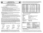
Novra S75 Receiver
Novra S75 Receiver Instructions
Subject to change without notification
Model: S75-0100
S/N: XXXX
Input: 24V
450mA
FCC ID: POIS750100
MAC:00-00-00-00-00-00
0560
This device complies with part 15 of the FCC rules. Operation is
subject to the following two conditions: (1) this device may not cause
harmful interference, and (2) this device must accept any interference
received, including interference that may cause undesired operation.
This device complies with the requirements of the European Directive
1999/5/EC
Made in CANADA
CAUTION: Any changes or modifications not expressly approved by the manufacturer could
void the user's authority to operate this equipment.
These Files have been optimized for printing.
Confidential and Proprietary
Version 52D3
1 of 20
Novra S75 Receiver
Novra S75 Receiver Instructions
Subject to change without notification
Document version: 52D3
________________________________
Important-
Please read this entire manual before installing or operating this product.
________________________________
Disclaimer
While reasonable effort has been made in the preparation of this document to assure its accuracy, Novra
Technologies Inc. assumes no responsibility for errors or omissions that may appear in this manual. Novra
reserves the right to change the contents of this manual at any time without notice.
Copyright
© 2002 Novra Technologies Inc. All rights reserved.
Information in this manual is subject to change without notice. No part of this manual may be reproduced or
transmitted in any form, by photocopy, microfilm, xerography, or any other means, or incorporated into any
information retrieval system, electronic or mechanical, for any purpose, without the express written permission
of Novra Technologies Inc.
For additional information or details on Novra's product offerings, please contact us at:
North American Headquarters 1100-330 St. Mary Avenue, Winnipeg, MB Canada R3C-3Z5
t. 204.989.4724
f. 204.989.4640
e. [email protected]
w. www.novra.com
Confidential and Proprietary
Version 52D3
2 of 20
Novra S75 Receiver
INDEX
Page
1.0
MINIMUM SYSTEM REQUIREMENTS
3
2.0
INTRODUCTION
2.1
Principle Of Operations
4
4
3.0
INSTALLATION
5
4.0
MANAGEMENT CONSOLE SYSTEM CONFIGURATIONS
6
5.0
6.0
4.1
4.2
Initial Communications
Network Configuration
6
9
4.3
Content Configuration
10
4.4
Satellite Configuration
MANAGEMENT CONSOLE DISPLAY DETAILS
11
12
5.1
Top Panel Button Functions
12
5.2
5.3
Status Information Window
Additional Status Information and Place Holders
13
14
5.4
Enhanced Hardware Device Management
15
S75 RECEIVER SPECIFICATIONS
17
APPENDIX
Miscellaneous Terms and Definitions
18
1.0 Minimum System Requirements
Your computer must have at least the following:
•
Processor: Pentium 566 MHz
•
RAM: 32 MB
•
Free disk space: 40 MB
•
Video: card and driver that support 256 or more colours
•
CD drive (required for software installation only)
•
Ethernet network interface card (NIC): 100 Mbps (100 BaseT)
NOTE: - The receiver may work with system parameters below those specified but
performance may be lacking.
NOTE: - Performance will
be highly dependant on other applications that your PC
is running.
Confidential and Proprietary
Version 52D3
3 of 20
Novra S75 Receiver
2.0 INTRODUCTION
2.1
Principles of Operation
Somewhere in the world is a location that transmits your signal, along with many others, up to a
satellite which turns around and transmits those signals back down to your location, and others. Your
satellite dish catches all these signals, and the electronics at the dish converts them all into a group
that travels down the cable to your S75 receiver. The S75 sifts through all the signals sent by the
satellite looking for your signal, a DVB data stream. The S75 then de-encapsulates the IP information
from the DVB stream and forwards it onto its final destination via a 100 Base-T Ethernet link.
The S75 also transmits status packets to your PC where the S75 Management Console is located.
The S75 Management Console is used to configure addresses, specify satellite tuning parameters
and select DVB information streams (PIDS). Once configured, the S75 will retain its settings and
continue to forward data transmitted to you by your service provider even after restarting the S75 or
your PC.
The S75 Receiver is meant to run in the background. In most cases, once the options have been set,
you will have no need to change them.
Confidential and Proprietary
Version 52D3
4 of 20
Novra S75 Receiver
3.0 INSTALLATION
S75 Receiver
Power
Supply
24 Vdc
RG6 Coax
(Center +ve)
Installation
Disk
(Cat 5
Crossover
Cable)
Supplied
Equipment
S75 Hardware Connections
1) Connect the S75 Receiver to the RG6 coax cable that is attached your satellite receiver.
2) Connect the 24 VDC adapter to the S75 .
3) Connect the Crossover Ethernet cable (Null-modem) between your PC's 100 BaseT NIC card and
the S75. (Or the S75 can be connected to the PC via a Hub with regular Ethernet cables.)
4) On your PC, create a file folder called "S75." The file folder can be under "Program Files" or in any
other location.
Note:
The system will create additional files containing various configuration aspects as they are
created. The system will locate these additional files in the same directory as the S75D
Management Console.exe program.
5) Copy the file S75D Management Console.exe from the CD ROM to the "S75" file folder.
6) Shortcuts can be created if desired through the normal Windows procedures.
7) Open (run) the S75D Management Console.exe and proceed to section 4.0.
CAUTION: Nothing should be inserted between the S75 and the satellite dish except for a surge
suppressor. Cable TV Splitters, TVs, VCRs, and FM receivers are not designed for connection to
this portion of the network. They will not work and if they are connected, even for a brief
moment, they will probably never work again because the power on the coax will destroy the
input of the misplaced unit.
Confidential and Proprietary
Version 52D3
5 of 20
Novra S75 Receiver
4.0 MANAGEMENT CONSOLE SYSTEM CONFIGURATIONS
4.1
Initial Communications
Open (run) the "S75D Management Console.exe" program.
The system will attempt to auto discover the S75 hardware that has already been connected and
establish communications parameters with it.
Confidential and Proprietary
Version 52D3
6 of 20
Novra S75 Receiver
It is not likely that the IP address the S75 shipped with will be valid for your network. Therefore, the
system will display this Warning message.
MAC Address of new S75.
IP Address that the S75
presently contains that does
not belong with the Network
group that it was connected to.
Press "OK" and the system will prompt you to change the S75 IP address with the following window.
Ethernet NIC cards that are present on your PC,
their IP Addresses and Subnet Masks.
MAC Address of the just installed S75.
IP Address of the just installed S75.
System suggested change.
Notice that the first three Octets of the suggested
"New IP Address" match the first three IP Address
Octets of Adaptor #0 (10.100.10). It is up to the
user choose the last Octet. In this case the system
arbitrarily selected "0". Any number from 0 to 255
System changed to
match existing
network IP Address
and Subnet format.
User selects .
would be acceptable as long as no other device
already has that IP address.
After entering the last Octet of the "New IP Address", press "OK" to continue the Auto Detect process.
Confidential and Proprietary
Version 52D3
7 of 20
Novra S75 Receiver
Once the auto detect process is completed, the Management Console display will look like this.
Drop Down List of detected devices showing their MAC Address and IP Address.
If there is only
one S75
attached to the
network, its
MAC and IP
Address will
appear in the
window.
If there are more
than one S75s
connected to the
network, they can
each be selected,
one at a time, by
highlighting them
in the drop down
"Selected Device"
menu.
Now that the Hardware and Software are talking to each other, it is time to set the other operational
parameters.
Note:
When there are multiple S75s connected to the network, and the Management Console is
opened, it will display the status for the first S75 it receives a status packet from. In other
words, the user should always ensure that they are looking at, and controlling the correct S75
by ensuring it is selected through the "Selected Device" drop down listing.
Confidential and Proprietary
Version 52D3
8 of 20
Novra S75 Receiver
4.2
Network Configuration
The Network Configuration Window can be opened with the tool bar button
or by selecting "Actions" then "Network Configuration" from the drop down menu.
This window will appear and allows the user
program various Networking aspects.
Receiver IP Address
The Desired Subnet Mask
The IP Address of the default Gateway
Selection of the Port that the PC software
will listen to for Status updates can be
chosen from the list of available ports
in the pull down menu.
Selection of a Destination IP Address
and UDP Port are not user configurable
in this version. At this time, this is a space
holder only and the values displayed are
arbitrary.
Push "Send" (or Enter) to assert the new settings or "Cancel" to exit this window without asserting the
changes.
This window will appear when the changes have
been successfully implemented.
Once the changes have been successfully applied, the Network Configuration window is closed by
selecting the "Cancel" button.
Confidential and Proprietary
Version 52D3
9 of 20
Novra S75 Receiver
4.3
Content Configuration
The Content Configuration Window can be opened with the tool bar button
or by selecting "Actions" then "Content Configuration" from the drop down menu.
The DVB signal from the satellite has Program IDentification (PID) numbers that are used to select
desired portions of the DVB data stream.
Enter the PID value in decimal
format.
The entered PID value is then
added to the Selected Contents
list and converted to Hex by the
system. (Displayed in brackets.)
Up to 16 PIDs can be listed at
once.
The "Delete" button will remove
a highlighted PID from the list while
"Delete All" will erase the entire list.
Notes: - There is no UNDO available. If "Delete All" was asserted in error then select "Cancel" to
abort the operation before the changes are applied to the S75.
- With this version of S75 De-encapsulation of the IP data is always selected.
(Selection of "Extract IP Data" is grayed out with a check mark.)
- The green check
indicates that the system will de-encapsulate the Multi-Protocol
Encapsulation (MPE) associated with the DVB stream.
Push "Send" (or Enter) to assert the new settings or "Cancel" to exit this window without asserting the
changes. Once the changes have been successfully applied, the Content Configuration window is
closed by selecting the "Cancel" button.
Confidential and Proprietary
Version 52D3
10 of 20
Novra S75 Receiver
4.4
Satellite Configuration
The Satellite Configuration Window can be opened with the tool bar button
or by selecting "Actions" then "Satellite Configuration" from the drop down menu.
Enter the desired Symbol Rate in Mega
Symbols per Second and the LBand
Frequency in Mega Hertz.
Select the "LNB Power On" box when
powering is required.
Once checked, the desired "Polarity"
and "Band" can be selected.
Push "Send" (or Enter) to assert the new settings or "Cancel" to exit this window without asserting the
changes.
This window will appear when the changes have
been successfully implemented.
Once the changes have been successfully applied, the Satellite Configuration window is closed by
selecting the "Cancel" button.
NOTE: Further LNB and Satellite information can be found in the Appendix.
Confidential and Proprietary
Version 52D3
11 of 20
Novra S75 Receiver
5.0 MANAGEMENT CONSOLE DISPLAY DETAILS
5.1
Top Panel Button Functions
Network Configuration
Content Configuration
Satellite Configuration
S75 System Reset
Minimize to System Tray
Exit Application
Network Configuration
see section 4.2
Content Configuration
see section 4.3
Satellite Configuration
see section 4.4
S75 System Reset
This function is rarely used. It will cause the S75 hardware to
restart itself as if the power had been removed and then returned.
System settings from the last "New Configuration Successfully
Applied" will be retained and reapplied when the Hardware
completes its Reset procedure.
Minimize to System Tray
This button reduces the Management Console to an icon in the
system tray capable of displaying Receive Signal status.
Receive Signal OK
Receive Signal Lost
Exit Application
This button will close the Management Console and the System Tray
icon. The Hardware will continue to function and forward data even
with the Management Console closed.
Confidential and Proprietary
Version 52D3
12 of 20
Novra S75 Receiver
5.2
Status Information Window
Select "Show Status"
to open the additional
window.
None of the configuration
variables can be set from
this window. It only
shows system status.
PID values that are being
used to filter the data stream.
Locked to an RF signal
Locked onto the Data Stream
This bar display indicates a relative strength of the received signal. Many factors contribute to the
value that is shown in this field. Any value displayed in this bar indicates that the system has sufficient
signal to work with. A better indication of signal quality is the Viterbi BER (Bit Error Rate) . A reading
of 2.0e-6 would indicate that the system is correcting, on average, 2 bits of data for every 1.0 million
bits received. Most errors occur not from low received signal levels but from to much adjacent
channel noise. The Viterbi BER value is the best indicator of receive signal quality.
Note:
The BER (Bit Error Rate) is calculated after a 100 million bits of information have been
received. For this reason, it may take several seconds for this field to update. i.e. A 2.0 Mega
Bit DVB Data Stream will require 50 seconds to accumulate 100 million bits. Higher data
rates will require less time.
Confidential and Proprietary
Version 52D3
13 of 20
Novra S75 Receiver
5.3
Additional Status Information and Placeholders
Additional Ethernet status information may be found by clicking here.
"Total Ethernet Packets Sent"
are the number of packets that have been de-encapsulated
and forwarded on.
"Ethernet Transmission Errors"
are the number of packets that contained errors.
"Total Ethernet Packets Received"
counts the number of packets that the S75 receives which
were addressed to it.
Content Configuration Packets will
cause this number to increment.
"Ethernet Receive Errors"
counts the number of packets sent to the S75 that had
errors.
"Ethernet Packets Dropped"
counts the number of IP packets that were ready to be
forwarded by the S75 but had to be dropped. (i.e. No
receiving mechanism was available.)
The counters are reset every time this window is opened.
The three entries in the DVB field are placeholders for future diagnostic tools.
Confidential and Proprietary
Version 52D3
14 of 20
Novra S75 Receiver
5.4
Enhanced Hardware Device Management
Enhanced S75 management, including network configurations, can be controlled though the use of
the "Manage Device List" accessed via the "Actions" dropdown menu.
The first step should always be to initiate "Auto-Detect Devices" to ensure that the "Current Device
List" is current.
Confidential and Proprietary
Version 52D3
15 of 20
Novra S75 Receiver
"Add Device Manually" should be used when the "Auto-Detect Devices" function fails to hear one of
the units. The user will need to know the MAC Address and IP Address assigned to the S75 in
question. After manually inputting this information the system will attempt to establish
communications with the new device. But, if the new S75 is not properly connected to the network or
is on a different network segment, this operation will not be successful.
"Check Device Status" will initiate communications between the highlighted device on the list and the
Management Console. This is equivalent to "Pinging" the device and results in a
appearing
next to the item in the list.
"Change IP Address" can be used at any time during the normal course of network administration to
assign a different IP Address to the highlighted S75. It will then be necessary to apply the "AutoDetect Devices" to update the "Current Device List." Ensure that the "Save and Exit" is used
otherwise the Management Console will not be able to control the settings or receive status packets
from the changed S75.
"Save and Exit" will;
1) save any changes that have been made to the PC's hard drive,
2) exit the "Manage Device List" window,
3) return to the S75 Management Console window.
"Exit without Saving" will not save any changes that have been made to the PC's hard drive.
Note:
With this command, any network changes that have been made to the S75s will not be
reflected in the "Manage Device List" the next time it is opened.
Confidential and Proprietary
Version 52D3
16 of 20
Novra S75 Receiver
6.0 S75 RECEIVER SPECIFICATIONS
RF Tuner
Hardware Capabilities
- Receiving Frequency: 950 to 2150 MHz
- Frequency Acquisition: ± 50% Symbol Rate up
to ± 10 MHz
- Input Signal Level: -65 dBm to -25 dBm
- Multiprotocol Encapsulation (MPE)
- PID Filters: 16
- Internal Hardware Watchdog
- Non-Volatile Configuration Storage
Operating Systems
QPSK
- Symbol Rates: 1.5 - 45 Msps
- Data Rate: 55 Mbps
- Root-raised cosine filter with roll-off 0.35
- Once Configured, Receiver Supports all
Operating Systems
Physical Interfaces
- RF Input Connector: F-Type, 75 ohms
- Ethernet 100 Base-T LAN Interface: RJ-45
FEC
- Decoding: Viterbi/Reed-Solomon
- Viterbi Inner Code: K=7, R=1/2, 2/3, 3/4, 5/6, 7/8
- Reed-Solomon Decoding: 204, 188, T=8
- Deinterleaving: Interleaving Depth=12
LNB Power and Switching
- LNB Supply Voltage: Selectable 13V, 18V or off
- LNB Control: 22 kHz Tone
- LNB Supply Current: 400 mA with Short Circuit
and Surge Protection
Configuration
- IP Address Configuration
- PID Selection
- LNB Power
- Transponder Settings: Symbol Rate, Frequency,
Polarization, Band, Power
- Management Console Application Currently
Available as both an Executable and a DLL for
MS Windows
Physical / Environmental
Height: 1.23 in. (3.12 cm)
Width: 5.22 in. (13.27 cm)
Depth: 3.90 in. ( 9.92 cm)
Operating Temperature: 0 C to 60 C
Storage Temperature: -55 C to 85 C
Operating Humidity: 10 - 90% Non-Condensing
Regulatory
- UDP/TCP/IP Protocol
- IP Multicast
- IGMP: V1.0, V2.0
- ETSI 301.192 DVB
- ISO/IEC 13818-1
- ISO/IEC 13818-6
- IEEE 802.3 10/100 Mbps
- FCC/Industry Canada
- CE
- Emission EN 55022
- Immunity EN 55024
- Safety EN 60950
Status Monitoring
- Signal Strength
- Signal Lock, Data Lock
- Error status: Viterbi BER, Uncorrectable Errors
Status Indicators
- Power: Red LED
- Signal: Green LED
- Lock: Green LED
- Ethernet Link and Transmit
Confidential and Proprietary
Version 52D3
17 of 20
Novra S75 Receiver
APPENDIX
Miscellaneous Terms and Definitions
Crossover Cable
A crossover cable is a cable that is used to connect two computers by reversing, or
crossing over, the cable pin contacts. This eliminates the need to use a hub when connecting
two PCs. It is also referred to as a "Null Modem" cable.
Coax Cable
Looks like this And is most commonly
used for Cable TV feeds inside a house or apartment. This form of cable allows the high
frequencies of TV, and Satellite type signals to move from one place to another with a
minimal amount signal loss.
DVB
Digital Video Broadcasting (DVB) is a set of standards that define digital broadcasting using
satellite, cable, and terrestrial infrastructures.
FEC
Forward Error Correction. A system of error control for data transmission where the receiving
device can detect and correct certain errors.
Feed Horn
This is the device that receives the focuses signals from a satellite dish. It collects these
signals and submits them to the next piece of equipment in the network, usually a Low Noise
Block converter which then changes the signals into a better format for transpiration to the
receiver.
Geostationary Orbit The position where a satellite is 35,786 kilometers (22,241 miles) above the equator.
At this distance, the satellite Orbits the earth at the same rate as the earth is turning. This
causes the satellite to appear stationary in relation to an observer on the ground.
IP
Internet Protocol. The network communication protocol used on Ethernet networks and the
Internet.
IP Address
The 32-bit computer address defined by the Internet Protocol. It is usually represented in
dotted decimal notation. Example: 192.168.111.112
L-Band
This range of frequencies is from 950 MHz to 2,150 MHz. It is much lower than those used by
satellites (About 1/10 to 1/6). Satellite frequencies travel well through space and our
atmosphere but do not do well through the cable that comes from the dish on the roof to the
receiver. So. LNBs convert satellite frequencies to the lower, easier to transport, band of
frequencies referred to as the L-Band. It is L-Band frequencies that the S75 receiver tunes to.
LNA
Older systems used a unit called an LNA Low Noise Amplifier. This unit amplifies the RF
frequency and then transmits the signals down a special (Expensive) cable to the reciever.
Note that received signals are not converted to lower frequencies by this unit.
LNBs
LNB stands for a Low Noise Block-converter. This unit receives the signals collected from a
satellite and converts their very high frequencies (12 Giga Hertz, written 12 GHz, which is
actually 12,000,000,000 cycles per second) to a lower and somewhat more usable range. All
LNBs have a Local Oscillator (LO). This number is usually stamped on the LNB but not
always. It may be necessary to check the original specifications that came with the LNB or
use the model number and brand name to search the Internet.
Confidential and Proprietary
Version 52D3
18 of 20
Novra S75 Receiver
LNBF
LNBF stands for a Low Noise Block-converter and Feed horn. This is quite a common
arrangement where the Feed Horn focal point that collects reflected signals from the satellite
dish is combined with the low noise block-converter into one package.
LO
Local Oscillator. This is a circuit that creates a tone of a very specific frequency. These units
have many applications in electronics. This important thing to remember is that there is an LO
in the LNB (Low Noise Block-converter) and it is part of the circuit that converts the received
satellite RF Frequencies to the more user friendly L-Band Frequencies. Typical values
include 9.75, 10.60, 10.75, 11.00 and 11.25 GHz for the Ku band and 5.15 GHz for the C
Band of satellite frequencies.
MAC Address The Media Access Control (MAC) address is the unique hardware address for any piece of
electronic equipment attached to a network. The MAC Address for your Novra S75 Receiver
is displayed on a sticker on the bottom of the receiver.
Mbps
Mega bits per second. (Million bits per second)
MBps
Mega Bytes per second. One "Byte" in computer terms is the same as 8 bits. It is often
referred to as a word.
1 MBps = 8 Mbps = 1 million Bytes (Words) per second = 8 million bits per second.
Msps
Mega symbols per second. Suppose you have four symbols, call them A, B, C & D. Let the
Symbol A represent two bits of data with the value 00.
Let B represent two bits of data with the value 01
Let C represent two bits of data with the value 10
Let D represent two bits of data with the value 11 (Or some other data scheme.)
This means that if the signals we are interested in consist of 1.0 Msps (That's 1 Million
symbols per second), and each symbols represents two bits of data, then our signal has a
data rate of 2.0 million bits per second (2.0 Mbps).
The important point to remember is that satellite systems send and receive symbols which
are then converted into data. The S75 takes the resulting data and forwards it to your
computer in bursts called "packets."
Packet
A packet is the unit of data that is routed between an origin and a destination. When any file
is sent from one place to another (the Internet as an example) it is divided into "chunks" of an
efficient size for routing. Each of these packets is separately numbered and includes the
Internet address of the destination.
PID
Packet Identification Code. This code is used by the receiver to sift through the different
packets of the transport stream. The transport stream contains data representing many
different signals. The S75 software running on your PC, uses the PID number to find only
those packets of data that contain the information you have requested. (See RF Frequency.)
Polarization, Circular In layman's terms, a circularly polarized signal corkscrews towards the earth.
(Right / Left)
Unlike linear polarization (described below), where the signal is fixed in an up and down
fashion or a side to side fashion, Circular Polarization causes the signal to rotate. If it were
possible to actually see the incoming signal, it would rotate like the hands on a clock. As with
Linear Polarization, this has two modes of operation. It can either rotate in a clock wise
fashion or counter clockwise. Polarization is very useful because it allows the frequency of a
Right polarized signal to overlap with the same frequencies of a Left polarized signal.
Polarization, Linear
In layman's terms, a linearly polarized signal from a satellite approaches the
(Horizontal /
earth as a wave that goes up and down like the waves on the ocean, or from side to side
Vertical)
like an intoxicated driver on the highway. These two types of waves are classified as being
Vertically or Horizontally polarized. Polarization is very useful because it allows the frequency
Confidential and Proprietary
Version 52D3
19 of 20
Novra S75 Receiver
of a Vertically polarized signal to overlap with the same frequencies of a Horizontally
polarized signal.
RAM
Random access memory. Used for short term storage of information requiring quick access
on a computer. Information stored in RAM can be accessed by the computer much faster
than information on the Hard Drive can be accessed.
RF Frequency Each satellite in orbit has several channels that it can use, each with its own RF Frequency.
(Each channel is often referred to as a transponder.) The easiest way to understand them is
to think of your FM radio. There are many channels on the FM dial that one can choose from.
("99.9 FM, All Rock, All the Time") When you input the station number to your FM receiver
you are actually telling it what RF Frequency it should look at. (99.9 FM means that 99.9
Mega Hz is the desired frequency.) But unlike the FM radio where the channel you tune to
only contains one stream of music, a satellite channel contains many individual signals. One
channel can contain Internet data and video and audio and specialized data in any number
of permutations and combinations. The S75 uses the PID numbers that come with each
Internet data, video, audio and specialized data signal to separate them all. (See PID.)
Satellite Signal Hierarchy
1 Satellite has |
10 - 24 Transponders (Channels) each with
|
dozens of distinct Rf Frequencies each containing
|
up to a theoretical maximum of 8190 packet streams identified by their individual PIDs.
Subnet
A portion of a network, which may be a physically independent network segment, and which
shares a network address with other portions of the network.
Symbol Rate
See Msps
Transponder
This is the unit on the satellite that receives a signal transmitted from the earth station,
amplifies it, changes its frequency and retransmits it back down to earth. Each radio channel
has its own transponder and a number of transponders on the satellite are used to cover the
allocated frequency band. A typical satellite will have 24 transponders.
Viterbi
"Convolutional encoding with Viterbi decoding is a Forward Error Correction technique that is
particularly suited to a channel in which the transmitted signal is corrupted mainly by additive
white gaussian noise." Further information can be found by searching the Internet or looking
at any of these sites.
http://pw1.netcom.com/~chip.f/Viterbi.html
http://hissa.nist.gov/dads/HTML/viterbiAlgorithm.html
http://www.mathworks.com/access/helpdesk/help/toolbox/commblks/ref/viterbidecoder.shtml
end.
Confidential and Proprietary
Version 52D3
20 of 20