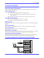
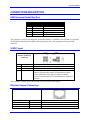
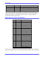
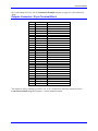
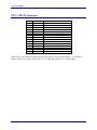
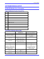
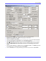
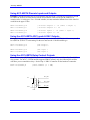
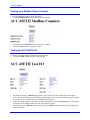
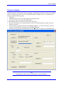
1
1^ USER MANUAL
^2 Accessory 65TH
^3 Modbus/TCP-IP UR Protected/OPTO
(Sourcing 24in/24out)
^4 3Ax-603830-xUxx
^5 November 21, 2007
Single Source Machine Control
Power // Flexibility // Ease of Use
21314 Lassen Street Chatsworth, CA 91311 // Tel. (818) 998-2095 Fax. (818) 998-7807 // www.deltatau.com
Copyright Information
© 2007 Delta Tau Data Systems, Inc. All rights reserved.
This document is furnished for the customers of Delta Tau Data Systems, Inc. Other uses are
unauthorized without written permission of Delta Tau Data Systems, Inc. Information contained in
this manual may be updated from time-to-time due to product improvements, etc., and may not
conform in every respect to former issues.
To report errors or inconsistencies, call or email:
Delta Tau Data Systems, Inc. Technical Support
Phone: (818) 717-5656
Fax: (818) 998-7807
Email: [email protected]
Website: http://www.deltatau.com
Operating Conditions
All Delta Tau Data Systems, Inc. motion controller products, accessories, and amplifiers contain
static sensitive components that can be damaged by incorrect handling. When installing or handling
Delta Tau Data Systems, Inc. products, avoid contact with highly insulated materials. Only
qualified personnel should be allowed to handle this equipment.
In the case of industrial applications, we expect our products to be protected from hazardous or
conductive materials and/or environments that could cause harm to the controller by damaging
components or causing electrical shorts. When our products are used in an industrial environment,
install them into an industrial electrical cabinet or industrial PC to protect them from excessive or
corrosive moisture, abnormal ambient temperatures, and conductive materials. If Delta Tau Data
Systems, Inc. products are directly exposed to hazardous or conductive materials and/or
environments, we cannot guarantee their operation.
REVISION HISTORY
REV.
1
DESCRIPTION
UPDATE 24 DC INPUT CONNECTOR TABLE, P.28
DATE
11/21/07
CHG
CP
APPVD
M. COGUR
Accessory 65ETH
Table of Contents
INTRODUCTION .......................................................................................................................................................1
Options ......................................................................................................................................................................1
HARDWARE REFERENCE SUMMARY ...............................................................................................................3
Product Layout ..........................................................................................................................................................3
Connectors and Indicators .........................................................................................................................................4
Inputs and Outputs LED Indicators......................................................................................................................4
Status LED Indicators...........................................................................................................................................4
Relay Status LED Indicators.................................................................................................................................4
USB Connector .....................................................................................................................................................4
24V Input Connector.............................................................................................................................................4
Ethernet Connector...............................................................................................................................................4
DB-15 Option-1 Connector ..................................................................................................................................4
Inputs and Outputs Terminal Blocks.....................................................................................................................4
Connections Example: Sourcing Inputs and Sourcing Outputs.................................................................................4
Connections Example: Sinking Inputs and Sourcing Outputs...................................................................................5
JUMPERS DESCRIPTION........................................................................................................................................7
E1: USB/Ethernet Micro Controller Firmware reload enable ..................................................................................7
CONNECTORS DESCRIPTION ..............................................................................................................................8
USB Universal Serial Bus Port .................................................................................................................................8
24VDC Input.............................................................................................................................................................8
Ethernet Copper Connectors .....................................................................................................................................8
Inputs Connector: 30-pin Terminal Block.................................................................................................................9
Outputs Connector: 30-pin Terminal Block ............................................................................................................10
OPT-1: DB-15 Connector .......................................................................................................................................11
SOFTWARE DESIGN & SETUP ............................................................................................................................12
ACC65-ETH Modbus Server Description...............................................................................................................12
Supported Modbus Function Codes (FC’s):.......................................................................................................12
ACC-65ETH I/O Modbus Memory Map .............................................................................................................12
Suggested PMAC ACC-65ETH I/O Memory Map ..............................................................................................13
Suggested PMAC Modbus Client Command List for above Memory Map.........................................................13
Using PeWinPro2 for Setting up Modbus ...............................................................................................................13
Using ACC-65ETH Discrete Inputs and Outputs....................................................................................................15
Using the ACC-65ETH ADC Inputs & DAC Outputs............................................................................................15
Using the ACC-65ETH Relay Contact Outputs ......................................................................................................15
Setting up your IP Address for the ACC-65ETH Card ...........................................................................................16
Viewing your Modbus Status Counters...................................................................................................................17
Testing the ACC-65ETH I/O ..................................................................................................................................17
Firmware Updates ...................................................................................................................................................18
Table of Contents
i
Accessory 65ETH
ii
Table of Contents
Accessory 65ETH
INTRODUCTION
The ACC-65ETH is a boxed accessory with 24 isolated self-protected digital inputs
and 24 isolated self-protected digital outputs. The inputs and outputs are controlled
through an Ethernet connector. The inputs are either sinking or sourcing (by user
wiring) at 12V to 24V levels. The outputs are sourcing, each at up to 24VDC with
600mA continuous and 1.2A peak for up to 2 seconds. An optional set of analog
inputs, analog outputs and relay contacts can be installed to control, for example,
one or two inverter drives through the Ethernet Modbus/TCP-IP link.
This accessory works with a PMAC or Turbo PMAC equipped with 100 Base T
Ethernet system that has Modbus option installed. In addition, this product conforms
to the Modbus specification other devices such as HMI, etc.
Options
•
OPT-1 (301-603830-OPT): This option includes:
Two relay contact outputs
Two 12-bit DAC outputs with 0 - ±10 V voltage range
Two 12-bit ADC inputs with 0- ±10 V voltage range
Introduction
1
Accessory 65ETH
2
Introduction
Accessory 65ETH
HARDWARE REFERENCE SUMMARY
Product Layout
Hardware Reference Summary
3
Accessory 65ETH
Connectors and Indicators
Inputs and Outputs LED Indicators
Each of the 24 input and 24 output lines has an associated LED that displays its state, either active or
inactive, in the front panel of the unit.
Status LED Indicators
+24V: When lit, this LED indicates that 24V is applied to the unit.
Fuse:
When lit, this LED indicates that the internal fuse protecting the external 24V is
properly functional.
PWR: When lit, this LED indicates that proper power is applied to the logic circuits
Relay Status LED Indicators
RLY1: When lit, this LED indicates that relay # 1 is activated.
RLY2: When lit, this LED indicates that relay # 1 is activated.
USB Connector
This connector is used to perform some software diagnostic procedures, or to download the operational
firmware.
24V Input Connector
Power is applied to the unit through this connector. The power requirements are 25A @ 24VDC
Ethernet Connector
Utilizes a Modbus/TCP-IP protocol to read from and write to all I/O.
DB-15 Option-1 Connector
When OPT-1 is ordered this connector provides the lines for two relay contact outputs, two 12-bit DAC
outputs with 0-20 V voltage range and two 12-bit ADC inputs with 0-20 V voltage range.
Inputs and Outputs Terminal Blocks
The digital inputs are connected through a 30-pin terminal block on the top panel of the unit, and the
digital outputs are connected through a 30-pin terminal block on the bottom panel of the unit.
Connections Example: Sourcing Inputs and Sourcing Outputs
Load
600 mA max
+
Symbol
1
5
OUT01
RET
24VDC Input
+
-
24V RET
+24V
ACC65ETH
25A @ 24VDC
Power Supply
OUTPUTS
Pin #
INPUTS
Input Switch
4
Pin #
Symbol
1
5
IN01
RET
Hardware Reference Summary
Accessory 65ETH
Connections Example: Sinking Inputs and Sourcing Outputs
Load
600 mA max
+
Symbol
1
5
OUT01
RET
24VDC Input
+
-
24V RET
+24V
ACC65ETH
25A @ 24VDC
Power Supply
OUTPUTS
Pin #
INPUTS
Input Switch
Hardware Reference Summary
Pin #
Symbol
1
5
IN01
RET
5
Accessory 65ETH
6
Hardware Reference Summary
Accessory 65ETH
JUMPERS DESCRIPTION
E1: USB/Ethernet Micro Controller Firmware reload enable
Jumper
Type
Description
Default
2-Pin
Micro Controller Firmware reload enable –
Factory default position is ON, and it should
remain ON. If the firmware was corrupted due to
a previous firmware download, the card firmware
may be reloaded by powering on the card with the
jumper off, installing the jumper without
powering off, then downloading firmware with
out powering off. Under normal circumstances,
this jumper should be on even when upgrading
firmware.
Jumpered
Jumpers Description
7
Accessory 65ETH
CONNECTORS DESCRIPTION
USB Universal Serial Bus Port
Pin #
1
2
3
4
5
6
Symbol
VCC
DD+
GND
SHELL
SHELL
Function
N.C.
DATADATA+
GND
SHIELD
SHIELD
This connector is only used to change the operational firmware. In addition, if the IP address is forgotten,
the EEPROM containing the IP address and configuration data can be programmed using the USB
connector.
24VDC Input
24V DC Input
Phoenix PCB Edge
Connector
Pin #
1
2
3
Symbol
GND
+24V Logic
+24V I/O
Function
Ground Connection from power supply
+24VDC input from power supply for logic
+24VDC input from power supply for I/O (Power supply
capacity depends on the number of simultaneous outputs
used in application. Each output is capable of 600mA
continues current output and 1.2A instantaneous output for 2
seconds)
This connector is used to power the unit with a 25A @ 24VDC power supply.
Ethernet Copper Connectors
Front View
8
Pin #
Symbol
Description
1
2
3
TX +
TX Unused
Transmit Output
Transmit Output
Connectors Description
Accessory 65ETH
4
5
6
7
8
Amber LED
Green LED
Unused
Unused
Unused
RX +
RX Activity
Link
Receive Input
Receive Input
Blinking indicates transmit/receive activity
Solid Green indicates a valid connection
The cable used for the Ethernet wired connections is CAT5. When wired to a hub/switch, a straightthrough 8 conductor cable can be used. When wired directly to a UMAC, a crossover cable must be used.
A solid green LED indicates a valid Ethernet hardware connection exists. A blinking amber LED
indicates Ethernet traffic is present on the wire.
Inputs Connector: 30-pin Terminal Block
PIN #
1
2
3
4
5
6
7
8
9
10
11
12
13
14
15
16
17
18
19
20
21
22
23
24
25
26
27
28
29
30
SYMBOL
IN01
IN02
IN03
IN04
RET
IN05
IN06
IN07
IN08
RET
IN09
IN10
IN11
IN12
RET
IN13
IN14
IN15
IN16
RET
IN17
IN18
IN19
IN20
RET
IN21
IN22
IN23
IN24
RET
FUNCTION
INPUT 1
INPUT 2
INPUT 3
INPUT 4
RETURN FOR INPUTS 1-8
INPUT 5
INPUT 6
INPUT 7
INPUT 8
RETURN FOR INPUTS 1-8
INPUT 9
INPUT 10
INPUT 11
INPUT 12
RETURN FOR INPUTS 9-16
INPUT 13
INPUT 14
INPUT 15
INPUT 16
RETURN FOR INPUTS 9-16
INPUT 17
INPUT 18
INPUT 19
INPUT 20
RETURN FOR INPUTS 17-24
INPUT 21
INPUT 22
INPUT 23
INPUT 24
RETURN FOR INPUTS 17-24
The inputs are sinking or sourcing by user wiring. For sinking inputs, connect the +24V side of the power
supply to the corresponding return line. For sourcing inputs, connect the GND side of the power supply to
Connectors Description
9
Accessory 65ETH
the corresponding return line. See the Connections Example diagrams on pages 4-5 of this manual for
details.
Outputs Connector: 30-pin Terminal Block
Pin #
1
2
3
4
5
6
7
8
9
10
11
12
13
14
15
16
17
18
19
20
21
22
23
24
25
26
27
28
29
30
Symbol
OUT01
OUT02
OUT03
OUT04
RET
OUT05
OUT06
OUT07
OUT08
RET
OUT09
OUT10
OUT11
OUT12
RET
OUT13
OUT14
OUT15
OUT16
RET
OUT17
OUT18
OUT19
OUT20
RET
OUT21
OUT22
OUT23
OUT24
RET
Function
OUTPUT 1
OUTPUT 2
OUTPUT 3
OUTPUT 4
RETURN FOR OUTPUTS 1-8
OUTPUT 5
OUTPUT 6
OUTPUT 7
OUTPUT 8
RETURN FOR OUTPUTS 1-8
OUTPUT 9
OUTPUT 10
OUTPUT 11
OUTPUT 12
OUTPUTS RETURN
OUTPUT 13
OUTPUT 14
OUTPUT 15
OUTPUT 16
OUTPUTS RETURN
OUTPUT 17
OUTPUT 18
OUTPUT 19
OUTPUT 20
OUTPUTS RETURN
OUTPUT 21
OUTPUT 22
OUTPUT 23
OUTPUT 24
OUTPUTS RETURN
The outputs are always sourcing type. Pins 5, 10, 15, 20, 25 and 30 are internally connected. See the
Connections Example diagrams on pages 4-5 of this manual for details.
10
Connectors Description
Accessory 65ETH
OPT-1: DB-15 Connector
Pin #
1
2
3
4
5
6
7
8
9
10
11
12
13
14
15
Symbol
GND
ADC1+
ADC2+
DAC1+
DAC2+
RLY -NC-1
RLY -COM-2
RLY -NO-2
ADC1ADC2DAC1DAC2RLY -COM-1
RLY -NO-1
RLY -NC-2
Function
COMMON GROUND
ANALOG INPUT 1+
ANALOG INPUT 2+
ANALOG OUTPUT 1+
ANALOG OUTPUT 2+
NORMALLY CLOSE RELAY 1
COMMON RELAY 2
NORMALLY OPEN RELAY 2
ANALOG INPUT 1ANALOG INPUT 2ANALOG OUTPUT 1ANALOG OUTPUT 2COMMON RELAY 1
NORMALLY OPEN RELAY 1
NORMALLY CLOSE RELAY 2
When OPT-1 is ordered this connector provides the lines for 2 relay contact outputs: 2 x 12-bit DAC
outputs with 0-±10 V voltage range, and 2 x 12-bit ADC inputs with 0-±10 V voltage range.
Connectors Description
11
Accessory 65ETH
SOFTWARE DESIGN & SETUP
ACC65-ETH Modbus Server Description
Supported Modbus Function Codes (FC’s):
FC
COMMAND DESCRIPTION
3
READ MULTIPLE REGISTERS X 4 WORDS
16
WRITE MULTIPLE REGISTERS X 4 WORDS
1
READ COILS X 24 COILS
2
READ INPUT DISCRETES X 24 DISCRETES
4
READ INPUT REGISTERS X 4 WORDS
5
WRITE ONE COIL
6
WRITE A SINGLE REGISTER
15
WRITE MULTIPLE COILS X 24 COILS
23
READ & WRITE MULTIPLE REGISTERS X 4 WORDS
ACC-65ETH I/O Modbus Memory Map
HARDWARE I/O
DIGITAL INPUTS 16
DIGITAL INPUTS 24 (INPUT 25 = 24VOK)
1
17
ANALOG INPUT 1
(12 BIT ADC)
ANALOG INPUT 2
(12 BIT ADC)
DIGITAL OUTPUTS 16 1
DIGITAL OUTPUTS 24 17
(OUTPUT 25 = RELAY1 ON,
OUTPUT 26 = RELAY2 ON
AND REMAINING BITS 27-32
ARE NOT USED)
ANALOG OUTPUT 1
(12 BIT DAC)
ANALOG OUTPUT 2
(12 BIT DAC)
12
MODBUS WORD
REFERENCE #
0
1
2
(LOWER 12 BITS ARE DATA,
UPPER 4 BITS STATUS)
3
(LOWER 12 BITS ARE DATA,
UPPER 4 BITS STATUS)
4
5
6
(UPPER 12 BITS ARE NOT
USED)
7
(UPPER 12 BITS ARE NOT
MODBUS INPUT DISCRETE
AND COIL REVERENCE #
INPUT DISCRETES 15 - 0
INPUT DISCRETES 23 - 16
(INPUT 24 = 24VOK, 26 - 32
ARE ZERO)
NA
NA
INPUT/OUTPUT COILS 15 0
INPUT/OUTPUT COILS 23 16
(COIL 24 = RELAY1 ON, COIL
25 = RELAY2 ON AND
REMAINING COILS 26-31
ARE NOT USED)
NA
NA
ACC-65M MACRO Card Memory and I/O Map
Accessory 65ETH
USED)
Suggested PMAC ACC-65ETH I/O Memory Map
PMAC
ADDRE
SS (I67
+)
PMAC
MODBU
S
REGIST
ER REF.
#
$90
32/33
PMAC
MODBU
S
DISCRE
TE/COI
L
REF. #
512 - 535
$91
$92
34/35
36/37
576 - 599
$93
38/39
ACC-65E
MODBUS
REGISTER
(DISCRETE
- COIL)
REF. #
PMAC X:
MEMORY
PARAMETER
PMAC Y: MEMORY
PARAMETER
0/1 (0-23)
DIGITAL INPUTS 15
–0
ADC INPUT 1
DIGITAL OUTPUTS
15 – 0
24VOK &
DIGITAL INPUTS 23 – 16
ADC INPUT 2
RLY1, RLY2 &
DIGITAL OUTPUTS 23 –
16
DAC OUTPUT 2
2/3
4/5 (0-23)
6/7
DAC OUTPUT 1
Suggested PMAC Modbus Client Command List for above Memory Map
MODBUS FUNCTION
CODE
23 READ/WRITE –
WRITE
23 READ/WRITE –
READ
MODBUS
REFERENCE #
4
PMAC REFERENCE
#
36
MODBUS COUNT
0
32
4
4
This will process all the Inputs and Outputs in one Modbus command. This Modbus Client command is
required to transfer all the I/O data to/from the PMAC and the ACC-65ETH I/O board via Modbus/TCPIP.
Using PeWinPro2 for Setting up Modbus
Note
The start of the PMAC Modbus Memory (I67) is in the upper 256 x 48 bit words
of a PMAC USER Buffer. This will vary given the PMAC but will remain fixed
for a given PMAC type and memory. The PMAC Modbus Server/Client buffer is
in the upper 128 x 48 bit words, thus always at I67 + $80. Our suggested memory
mapping for the ACC-65ETH is at I67 + $90 leaving the $80 - $8F for another
PMAC Modbus feature used by I69. I69 allows the developer to directly control
the PMAC without PLCs.
Select the PMAC that will be the Modbus/TCP-IP Client (the Master). Then select the Configure>Modbus Setup window. You should see a screen similar to the following after configuring your PMAC
for Modbus communication.
Accessory 65ETH
•
•
•
•
•
•
•
•
•
14
First select Setup Modbus. You may get another value for your Modbus address.
Enable I69 and set Addr. Offs = 128 if you are going to use that feature.
Setup one of Sockets 1-3 as a Client.
If you are using the recommended memory map, set up the above recommended Client Command.
Set the Server IP Address = 192.6.94.50 or your ACC-65ETH IP address.
Select Test Network you should have a success if your ACC-65ETH is connected to your network.
This button will test (Ping) and connect (Route ) your ACC-65ETH IP address on your network.
Select the Update PMAC button and the PMAC should now be communicating with your ACC65ETH.
Select the Active Socket that is a Client and then select Refresh Counters. The Modbus cnt should
be counting if you are communicating with the ACC-65ETH.
If not use PeWinPro2 to test (Ping and Routing) your Ethernet network with the ACC-65ETH.
ACC-65M MACRO Card Memory and I/O Map
Accessory 65ETH
Using ACC-65ETH Discrete Inputs and Outputs
Example: Using the suggested ACC65-ETH memory map and an I67 = $3FF00, the I/O memory would
be at $3FF90 - $3FF93. For the discrete I/O the user could use a DP (32 bit) type M-variable or a
variation of the 1-16 bit types. For a 32 bit M-variable, one must remember that the first 16 bit of the I/O
would be in the upper 32 bits.
M300->X:$3FF92,0,16
M301->Y:$3FF92,0,8
; Discrete Outputs 1 – 16 (LSbit = Output 1)
; Discrete Outputs 17 - 24
M400->X:$3FF90,0,16
M401->Y:$3FF90,0,8
; Discrete Inputs 1 – 16 (LSbit = Input 1)
; Discrete Inputs 17 - 24
Using the ACC-65ETH ADC Inputs & DAC Outputs
Example: Using the suggested ACC65-ETH memory map and an I67 = $3FF00, the I/O memory would
be at $3FF90 - $3FF93. For the analog I/O the user must use the 12 bit M-variable type
M320->X:$3FF93,0,12
M321->Y:$3FF93,0,12
;DAC Output 1
;DAC Output 2
M420->X:$3FF91,0,12
M421->Y:$3FF91,0,12
;ADC Input 1
;ADC Input 2
Using the ACC-65ETH Relay Contact Outputs
There are two relays (RLY1 and RLY2) each with a Normally Open (NO) and a Normally Closed (NC)
relay contact. For an I67 = $3FF00 and the suggested PMAC memory map, the following M-variables
will allow you to control these relays. See the Opt-1: DB-15 Connector for the hardware connection.
M310->Y:$3FF92,8
M311->Y:$3FF92,9
; RLY1 Enable (1 = ON)
; RLY2 Enable (1 = ON)
RLYx_NO
5V+
RLYx_COM
RLYx_NC
RLYx
Isolation
Accessory 65ETH
Setting up your IP Address for the ACC-65ETH Card
To update the IP address of the ACC-65ETH, do the following:
• Load your Web browser and type in the Address: http://192.6.94.50 (the default) or its current IP
address.
• If you get “This page cannot be displayed” go to PewinPro2 for help in testing your Ethernet
connection and setting up your Routing address table.
• If you get the following data in your browser, select SetIP.
•
You should get the following screen.
•
•
•
Change the current IP and or Subnet Mask addresses and then select the Update button.
You must recycle power to the ACC-65ETH card for the new addressing to take effect.
Don’t forget your new IP address because otherwise you will not be able to connect to the card over
Ethernet. If you do, you must use the USB firmware downloader to determine or set your IP address.
16
ACC-65M MACRO Card Memory and I/O Map
Accessory 65ETH
Viewing your Modbus Status Counters
To view the Modbus Counters do the following:
• Selecting ModbusCntrs should show the following data:
•
•
Select the browser Refresh button to update the counters.
Select the Clear button to clear the counters.
Testing the ACC-65ETH I/O
To test the I/O independently of Modbus do the following:
• Selecting TestIO should show the following data:
•
•
•
Selecting the browser’s Refresh button allows you to observe the last outputs and current inputs.
This is useful and allowed during Modbus communication. So as to not overload the processor, allow
at least one to two seconds between refreshing the displayed I/O.
Enter the desired outputs on the right side of the page and then select the Update button. The outputs
and inputs will be updated at the card and in the display registers.
Select the browser’s Refresh button or the Web Server Update button to output your selections and
update the inputs.
Accessory 65ETH
Firmware Updates
The latest firmware is loaded at the factory be shipping. Downloading new firmware to the ACC-65ETH
IO Device should only be done if you are instructed by Delta Tau support to do so. To download new
firmware, obtain the following items:
• USB Cable
• USBEthConfigure Software included with the Pewin32Pro2 Suite
• New firmware file for example ACC65ETH100.iic
To download the software to the ACC-65ETH, do the following:
1. Place the USB cable to the J2 USB connection on the ACC-65ETH and place the other end to the
USB port on the PC.
2. Power up the ACC-65ETH and then launch USBEthConfigure.exe. Choose the firmware file (for
example ACC65ETH100.iic) and then press the Store F/W button.
3. After the message appears indicating that the firmware download is complete click the Done button.
Note
If needed, this is another avenue to determine or set your IP address.
18
ACC-65M MACRO Card Memory and I/O Map