1
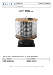
Obelux SAL 14.01.2014 User Manual USER MANUAL This User Manual applies to following Obelux SAL aviation obstacle lights: Obelux MI-20KW Obelux MI-20KW-x-A Obelux MI-20KWD-x-A Obelux HI-50KW Obelux HI-50KW-x-A Obelux HI-50KWD-x-A Technical information in this document is subject to change without notice. Copyright © Obelux Oy 2013 Page 1/20 Obelux SAL 14.01.2014 Page 2/20 User Manual Table of contents 1 Overview ................................................................................................................................................................... 3 2 Models ...................................................................................................................................................................... 3 2.1 Medium Intensity ............................................................................................................................................... 3 2.1.1 20 000 cd white ......................................................................................................................................... 3 2.1.2 20 000 cd white and 2 000 cd red ............................................................................................................. 3 2.2 High Intensity..................................................................................................................................................... 4 2.2.1 50 000 cd white ......................................................................................................................................... 4 2.2.2 50 000 cd white and 2 000 cd red ............................................................................................................. 4 2.3 Common elements in all models ....................................................................................................................... 5 3 Options ..................................................................................................................................................................... 5 4 Dimensions ............................................................................................................................................................... 6 5 Parts ......................................................................................................................................................................... 7 6 Options ..................................................................................................................................................................... 9 6.1 Ethernet/IP network ........................................................................................................................................... 9 6.2 GPS ................................................................................................................................................................... 9 6.3 Infrared ............................................................................................................................................................ 10 7 Installation .............................................................................................................................................................. 10 7.1 Verify model .................................................................................................................................................... 10 7.2 Configuration ................................................................................................................................................... 10 7.2.1 Light ......................................................................................................................................................... 11 7.2.2 Flash rate ................................................................................................................................................ 11 7.2.3 Night mode parameters ........................................................................................................................... 12 7.2.4 Device mode ........................................................................................................................................... 12 7.2.5 RS-485 bus termination .......................................................................................................................... 12 7.3 Mounting .......................................................................................................................................................... 13 7.3.1 Physical installation ................................................................................................................................. 13 7.3.2 Alarm relay .............................................................................................................................................. 13 7.3.3 Wiring ...................................................................................................................................................... 13 7.3.4 Testing ..................................................................................................................................................... 14 7.3.5 Post-installation actions .......................................................................................................................... 14 7.3.6 Power-On ................................................................................................................................................ 14 8 Status indications ................................................................................................................................................... 14 9 Causes for ALARM ................................................................................................................................................. 15 10 Testing .................................................................................................................................................................... 15 10.1.1 Functional test ......................................................................................................................................... 15 10.1.2 Light head test ......................................................................................................................................... 16 11 Configuration example............................................................................................................................................ 16 12 Troubleshooting ...................................................................................................................................................... 17 13 Spare parts ............................................................................................................................................................. 18 14 Configuration sheets............................................................................................................................................... 19 14.1 Normal operation ............................................................................................................................................. 19 14.2 Test mode ....................................................................................................................................................... 20 15 Change log ............................................................................................................................................................. 20 Technical information in this document is subject to change without notice. Copyright © Obelux Oy 2013 Obelux Oy phone +358 9 6871 6800 Kutomotie 6 B fax +358 9 621 5518 FI-00380 http://www.obelux.com Obelux SAL User Manual v2.2 FINLAND [email protected] HELSINKI Obelux SAL 14.01.2014 Page 3/20 User Manual 1 Overview Obelux MI-20KW-x-A is aviation obstacle light product to customers needing an obstacle light that provides 20 000 cd white and can provide 2 000 cd red (model MI-20KWD-x-A) and/or infrared beacons in the same unit with factoryinstalled options. White light can be dimmed in night mode. Respectively, Obelux HI-50KW-x-A is aviation obstacle light product to customers needing an obstacle light that provides 50 000 cd white and can provide 2 000 cd red (model HI-50KWD-x-A) and/or infrared beacons in the same unit with factory-installed options. White light can be dimmed in twilight and night modes. Replace –x- with operating voltage. Values are presented in tables below. 2 Models 2.1 Medium Intensity 2.1.1 20 000 cd white This obstacle light is available in following configurations: Light output: 20 000 cd white Voltage Obelux product code 100 V AC Obelux MI-20KW-100-A 115 V AC Obelux MI-20KW-115-A 200 V AC Obelux MI-20KW-200-A 230 V AC Obelux MI-20KW-230-A Obelux MI-20KW-x-A, being a 20 000 cd product, meets the light output specifications of ICAO Medium Intensity Type A and FAA L-865, L-866. ICAO Medium Intensity, Type A (flash rate 20 – 60 fpm) FAA Medium Intensity, Type L-865 (flash rate 40 fpm) FAA Medium Intensity, Type L-866 (flash rate 60 fpm) Mode Light output Day 20 000 cd ± 25% flashing white Twilight 20 000 cd ± 25% flashing white Night 2 000 cd ± 25% flashing white 2.1.2 20 000 cd white and 2 000 cd red This obstacle light is available in following configurations: Light output: 20 000 cd white and 2 000 cd red Voltage Obelux product code 100 V AC Obelux MI-20KWD-100-A 115 V AC Obelux MI-20KWD-115-A 200 V AC Obelux MI-20KWD-200-A 230 V AC Obelux MI-20KWD-230-A Obelux MI-20KWD-x-A meets the following light output specifications (user-selectable): Technical information in this document is subject to change without notice. Copyright © Obelux Oy 2013 Obelux Oy phone +358 9 6871 6800 Kutomotie 6 B fax +358 9 621 5518 FI-00380 http://www.obelux.com Obelux SAL User Manual v2.2 FINLAND [email protected] HELSINKI Obelux SAL 14.01.2014 Page 4/20 User Manual ICAO Medium Intensity, Type A (flash rate 20 – 60 fpm) FAA Medium Intensity, Type L-865 (flash rate 40 fpm) FAA Medium Intensity, Type L-866 (flash rate 60 fpm) Mode Light output Day 20 000 cd ± 25% flashing white Twilight 20 000 cd ± 25% flashing white Night 2 000 cd ± 25% flashing white ICAO Medium Intensity, Type B (flash rate 20 – 60 fpm) FAA Medium Intensity, Type L-864 (flash rate 20-40 fpm) FAA Medium Intensity, Type L-885 (flash rate 60 fpm) Mode Light output Day N/A Twilight N/A Night 2 000 cd ± 25% flashing red ICAO Medium Intensity, Type C Mode Light output Day N/A Twilight N/A Night 2 000 cd ± 25% fixed red (“steady burning”) 2.2 High Intensity 2.2.1 50 000 cd white Obelux HI-50KW-x-A is high-Intensity obstacle light designed especially for wind-mill applications where civil aviation authority for aviation security allows using two (or more) 50 000 cd units instead of one 100 000 cd unit. This product is a replacement to 100,000 cd high intensity aviation obstacle light only in cases where local authority allows using two or more 50 000 cd (white) obstacle lights instead of 100 000 cd (white) obstacle light. With two or more HI-50KW obstacle lights, this product conforms to performance required from ICAO High Intensity Type B and it meets regulations set by Finnish Civil Aviation Authority (part of Finnish Transport Safety Agency). Light output: 50 000 cd white Voltage Obelux product code 100 V AC Obelux HI-50KW-100-A 115 V AC Obelux HI-50KW-115-A 200 V AC Obelux HI-50KW-200-A 230 V AC Obelux HI-50KW-230-A 2.2.2 50 000 cd white and 1 000 cd red This obstacle light is available in following configurations: Technical information in this document is subject to change without notice. Copyright © Obelux Oy 2013 Obelux Oy phone +358 9 6871 6800 Kutomotie 6 B fax +358 9 621 5518 FI-00380 http://www.obelux.com Obelux SAL User Manual v2.2 FINLAND [email protected] HELSINKI Obelux SAL 14.01.2014 Page 5/20 User Manual Light output: 50 000 cd white and 1 000 cd red Voltage Obelux product code 100 V AC Obelux HI-50KWD-100-A 115 V AC Obelux HI-50KWD-115-A 200 V AC Obelux HI-50KWD-200-A 230 V AC Obelux HI-50KWD-230-A Like HI-50KW-x-A, with two or more HI-50KW obstacle lights, this product conforms to performance required from ICAO High Intensity Type B and it conforms to regulations issued by Finnish Transport Safety Agency. Obelux HI-50KWD-x-A meets the following light output specifications: [TraFi - Finland] Mode Day Twilight Night Light output 50 000 cd ± 25% flashing white 10 000 cd ± 25% flashing white 1 000 cd ± 25% flashing white Mode Day Twilight Night Light output N/A N/A 1 000 cd ± 25% flashing red Mode Day Twilight Night Light output N/A N/A 1 000 cd ± 25% fixed red (“steady burning”) 2.3 Common elements in all models No external controllers are required to install and run these products. In most use cases, mounting the standalone aviation obstacle light and connecting power supply cable are the only actions needed to operate this light. These models come with built-in photocell that can drive the transitions between day, twilight and night modes. In some ICAO aviation obstacle light types, twilight mode is not specified and day mode is used until night. Various operating modes and responses to parameters are realised using embedded microcontroller on the controller card. These Obelux aviation obstacle lights are Class 2M LED device. This class is safe for accidental viewing under all operating conditions. However, it may not be eye-safe for a person who deliberately stares into the LED beam by overcoming their natural aversion response to the very bright light. 3 Options These Obelux standalone aviation obstacle lights can be extended with factory-installed options like GPS synchronisation, Ethernet/IP interface and infrared LEDs. Infrared LEDs are typically used to achieve NVG compatibility. Technical information in this document is subject to change without notice. Copyright © Obelux Oy 2013 Obelux Oy phone +358 9 6871 6800 Kutomotie 6 B fax +358 9 621 5518 FI-00380 http://www.obelux.com Obelux SAL User Manual v2.2 FINLAND [email protected] HELSINKI Obelux SAL 14.01.2014 Page 6/20 User Manual GPS synchronisation is an industry-wide solution to make aviation obstacle lights to synchronise their flashing regardless of location. These models can even be controlled and monitored from a remote control room using optional Ethernet/IP interface. Factory-installable options available: For Obelux MI-20KW-x-A Option OPT-GPS-20KW-A OPT-IR-20KW-A OPT-LAN-20KW-A Added functionality GPS Receiver Infrared (855 nm) Ethernet/IP interface For Obelux MI-20KWD-x-A Option OPT-GPS-20KWD-A OPT-IR-20KWD-A OPT-LAN-20KWD-A Added functionality GPS Receiver Infrared (855 nm) Ethernet/IP interface For Obelux HI-50KW-x-A Option OPT-GPS-50KW-A OPT-IR-50KW-A OPT-LAN-50KW-A Added functionality GPS Receiver Infrared (855 nm) Ethernet/IP interface For Obelux HI-50KWD-x-A Option OPT-GPS-50KWD-A OPT-IR-50KWD-A OPT-LAN-50KWD-A Added functionality GPS Receiver Infrared (855 nm) Ethernet/IP interface Options are ordered together with the aviation obstacle light. Installing OPT-IR makes this product compliant with NVGs (Night Vision Goggles). 4 Dimensions All dimensions stated in illustrations are in millimetres (mm). Technical information in this document is subject to change without notice. Copyright © Obelux Oy 2013 Obelux Oy phone +358 9 6871 6800 Kutomotie 6 B fax +358 9 621 5518 FI-00380 http://www.obelux.com Obelux SAL User Manual v2.2 FINLAND [email protected] HELSINKI Obelux SAL 14.01.2014 Page 7/20 User Manual Mechanical dimensions Mechanical dimensions – Mounting plate 5 Parts User-accessible parts are illustrated and explained in the table below. These parts are accessible through the service access hatch on the lower chassis area. Technical information in this document is subject to change without notice. Copyright © Obelux Oy 2013 Obelux Oy phone +358 9 6871 6800 Kutomotie 6 B fax +358 9 621 5518 FI-00380 http://www.obelux.com Obelux SAL User Manual v2.2 FINLAND [email protected] HELSINKI Obelux SAL 14.01.2014 Page 8/20 User Manual Connectors on the system board are designed to house mains power supply wires of size up to 4(6) mm2 nominal cross section and communications cable wires of size up to 1.5 mm2. Power supply cable wires are secured using screw terminals; the communication cable wires are secured using spring-cage clamp terminals. To release wire from terminal block, push the orange lever on top of connector chassis backwards to open the terminal. A slot head screwdriver is recommended. Technical information in this document is subject to change without notice. Copyright © Obelux Oy 2013 Obelux Oy phone +358 9 6871 6800 Kutomotie 6 B fax +358 9 621 5518 FI-00380 http://www.obelux.com Obelux SAL User Manual v2.2 FINLAND [email protected] HELSINKI Obelux SAL 14.01.2014 Page 9/20 User Manual Controller board 1 2 3 4 5 6 7 Software version label Mains power supply connector (Single-phase supply with Protective Earth) Alarm relay connector Communications network connector (RS-485 or Ethernet/IP RJ-45) External signal input connector Configuration DIP switches (1-10) Status LEDs 6 Options Obstacle light may have factory-installed Ethernet/IP and/or GPS options already mounted on the controller board. 6.1 Ethernet/IP network Ethernet/IP option replaces RS-485; if Ethernet/IP is equipped, the RS-485 is unavailable. Ethernet/IP enables remote control and monitoring without RS-485 bus, allowing longer distances and monitoring off-site. 6.2 GPS GPS receiver makes it possible to synchronise obstacle lights to external clock (GPS time). This option is typically used in master units or non-networked lights to have all aviation obstacle lights to follow same flashing pattern. External GPS antenna is located on top of light. Technical information in this document is subject to change without notice. Copyright © Obelux Oy 2013 Obelux Oy phone +358 9 6871 6800 Kutomotie 6 B fax +358 9 621 5518 FI-00380 http://www.obelux.com Obelux SAL User Manual v2.2 FINLAND [email protected] HELSINKI Obelux SAL 14.01.2014 Page 10/20 User Manual 6.3 Infrared Obstacle light may have factory-installed Night Vision Goggles-compatible infrared LEDs. 7 Installation 7.1 Verify model Find the Obelux product label on the light and note the product model. It should state the light output and operating voltage of that particular light. Use the following information to decode Obelux product label information: Product code (sample) Obelux MI 1 - 50KW 2 - 230 3 - A 4 1 HI MI Serie High Intensity Medium Intensity 2 20KW 20KWD 50KW 50KWD Light output 20 000 cd white 20 000 cd white and 2 000 cd red 50 000 cd white 50 000 cd white and 2 000 cd red 3 100 115 200 230 Operating voltage (AC only) 100 V AC 115 V AC 200 V AC 230 V AC 4 A Standalone Standalone model Using information on the product label, check and verify that the product matches supply voltage on the site. Incorrect voltage on the supply terminals can cause permanent damage on this device. Using incorrect supply voltage also voids the product warranty. 7.2 Configuration Open all four (4) screws that secure the service access hatch to the chassis using a slot-head screwdriver. You do not need to remove the screws completely to open this hatch. Hatch is secured using a strap between hatch and chassis. Using the DIP switches visible and accessible via service access opening, configure the desired parameters into standalone light. To configure this light the following parameters shall be set according to the local regulations and permit: Technical information in this document is subject to change without notice. Copyright © Obelux Oy 2013 Obelux Oy phone +358 9 6871 6800 Kutomotie 6 B fax +358 9 621 5518 FI-00380 http://www.obelux.com Obelux SAL User Manual v2.2 FINLAND [email protected] HELSINKI Obelux SAL 14.01.2014 Page 11/20 User Manual Operating mode during night time (e.g. ICAO Medium-Intensity Type B: flashing-red, Type C: fixed-red) Flash rate (flashes per minute) DIP switch #9 is unused. DIP switch #10 controls RS-485 communication bus termination. When this DIP switch is turned ON (i.e. facing up), the 120Ω termination resistor is connected to the RS-485 bus on the controller board. DIP switches are numbered 1-10, the lowest number (1) being on the leftmost edge of the red/white DIP switch block looked from service access door. Embedded software in the obstacle light reads configuration switches regularly. Configuration change becomes effective within few seconds. 7.2.1 Light The controller board shall be configured according to the hardware installed in the aviation obstacle light i.e. as the aviation obstacle light has been manufactured. Some alternatives in the table below may be inapplicable to a certain product (i.e. 20 000 cd light MI-20KW cannot operate as HI-50KW providing 50 000 cd light and fulfilling requirements). Make sure that you return the proper configuration setting in case test mode (explained below) has been engaged and required tests have been carried out. 1 off down on up off down on up DIP switch 2 off down off down on up on up Light 3 off down off down off down off down MI-20KW 20 000 cd white (flashing) MI-20KWD 20 000 cd white (flashing) and 2 000 cd red MI-20KW with OPT-IR-20KW-A 20 000 cd white (flashing) and infrared MI-20KWD with OPT-IR-20KWD-A 20 000 cd white (flashing), 2 000 cd red and infrared The red light on MI-20KWD is disabled when DIP switch #1 is off. 1 off down on up off down on up DIP switch 2 off down off down on up on up Light 3 on up on up on up on up HI-50KW 50 000 cd white (flashing) HI-50KWD 50 000 cd white (flashing) and 2 000 cd red HI-50KW with OPT-IR-50KW-A 50 000 cd white (flashing) and infrared HI-50KWD with OPT-IR-50KWD-A 50 000 cd white (flashing), 2 000 cd red and infrared The red light on HI-50KWD is disabled when DIP switch #1 is off. 7.2.2 Flash rate DIP switches #4 and #5 control the flash rate. Standard controller can run the light with following flash rates. Customer-specific flash rates are available on request. Technical information in this document is subject to change without notice. Copyright © Obelux Oy 2013 Obelux Oy phone +358 9 6871 6800 Kutomotie 6 B fax +358 9 621 5518 FI-00380 http://www.obelux.com Obelux SAL User Manual v2.2 FINLAND [email protected] HELSINKI Obelux SAL 14.01.2014 Page 12/20 User Manual DIP Switch 4 5 off off down down on off up down off on down up on on up up Flash rate 20 fpm (flashes per minute); one flash in three seconds 30 fpm (flashes per minute); one flash in two seconds 40 fpm (flashes per minute); one flash in 1.5 seconds 60 fpm (flashes per minute); one flash in every second 7.2.3 Night mode parameters Using DIP switch #6, the flashing mode for red (models MI-20KWD and HI-50KWD) and infra-red (models with OPTIR) can be set. DIP Switch 6 off down on up Night mode Red and infrared (IR) lights flash at the selected flash rate. Red and infrared (IR) lights are burning steady. 7.2.4 Device mode Using DIP switch #8, the obstacle light can be set to operate as master in network. Only one obstacle light shall be master in a network domain. Master unit broadcasts time and illumination data to slave units. Time is typically received from GPS and illumination information comes from photocell (internal or external). If the information flow from master unit to slave units is interrupted, the slave units will use local photocell setting and local clock (time) in their operations. As data flow resumes, the slaves automatically synchronise themselves with master unit. DIP Switch 8 off down on up Device mode select This unit is a slave in the Obelux aviation obstacle lighting system/network. This unit is master in the Obelux aviation obstacle lighting system/network. 7.2.5 RS-485 bus termination DIP Switch 10 off down on up RS-485 termination RS-485 bus not terminated on controller board. RS-485 bus terminated to 120Ω on controller board. Technical information in this document is subject to change without notice. Copyright © Obelux Oy 2013 Obelux Oy phone +358 9 6871 6800 Kutomotie 6 B fax +358 9 621 5518 FI-00380 http://www.obelux.com Obelux SAL User Manual v2.2 FINLAND [email protected] HELSINKI Obelux SAL 14.01.2014 Page 13/20 User Manual 7.3 Mounting 7.3.1 Physical installation Mount the obstacle light to selected mounting point using quality-made fasteners. This Obelux standalone light comes with four bolt holes to mount this product securely. Photocell is located under top lenses row. See illustration on page 8 for more information. Level the light using spirit level (bubble level) if the mounting point is not already levelled. Tighten bolts & nuts. Obelux recommends 100 Nm tightening torque for M12 hot-dipped 8.8 bolts with suitable washer between bolt and mounting plate. 7.3.2 Alarm relay NC COM NC COM NO NO Alarm relay during normal operation Alarm relay during start-up, active alarm and/or during loss-of-power When the controller board starts, after a short delay, the contacts NC (Normally Connected) and COM (Common) are short-circuited. During normal operation, terminals ALARM COM and ALARM NC are connected i.e. short-circuited. If an alarm is raised, ALARM COM and ALARM NO are short-circuited with the short-circuiting link between ALARM COM and ALARM NC is removed. Note that the ALARM COM and ALARM NO are short-circuited when controller card is starting and running the startup tests. 7.3.3 Wiring Open the service access hatch. Connect the RS-485 bus (if applicable), alarm relay cables (if applicable) and mains power supply cable wires securely to appropriate terminal block connectors. Route cables using cable glands on the right side of obstacle light. Note polarity. Mains power (N, L, PE) Conductor cross section solid and stranded min. 0.5 mm2 Conductor cross section solid max. 6 mm2 Conductor cross section stranded max. 4 mm2 Minimum AWG according to UL/CUL is 24 and maximum AWG is 10. Technical information in this document is subject to change without notice. Copyright © Obelux Oy 2013 Obelux Oy phone +358 9 6871 6800 Kutomotie 6 B fax +358 9 621 5518 FI-00380 http://www.obelux.com Obelux SAL User Manual v2.2 FINLAND [email protected] HELSINKI Obelux SAL 14.01.2014 Page 14/20 User Manual Signal wires Conductor cross section solid and stranded min. 0.2 mm2 0.2 mm2 Signals: Alarm Signals: RS-485 bus Conductor cross section solid and stranded max. 1.5 mm2 1.5 mm2 RS-485 bus is unavailable on standalone models having Ethernet/IP option installed. With this Ethernet option installed, use high-grade CAT5 (or better) Ethernet copper cable and RJ-45 connectors. 7.3.4 Testing If needed, operations of the Obelux MI-20KW-x-A and HI-50KW-x-A lights can be tested using test mode. Further information is available on chapter 10 (see page 15). Restore normal operation mode when testing has been completed. For testing, the mains power supply to the light must be available. Ambient light is measured using photocell under glass cover on top of light. To avoid too frequent changes of intensity level, the new ambient light level must be constantly active for more than three minutes in normal operations mode. Test mode provides rapid feedback. 7.3.5 Post-installation actions Place the service access hatch properly on its place and securely tighten all four screws on the corners of this hatch. 7.3.6 Power-On The obstacle light starts with daytime intensity level. Depending on the light, the first flashes will be at 20 000 cd or 50 000 cd effective intensity. After three minutes, the intensity level can be decreased to twilight or night mode with information from photocell. 8 Status indications Status indications are LEDs mounted on the controller board in front of configuration DIP switches. Some of the status indicators have three operating states (off, lit and blinking). Indicators listed below follow their order (from left to right) on the controller board. This Obelux standalone light has five (5) status LEDs on the controller board. These status LEDs are visible only when service access hatch is open. Indicator Colour: off on Indicator Colour: off on blinking fast blinking slowly Green 3V3 Power off. Unit is powered on. Green PC Photocell not in use Day mode Twilight mode Night mode Technical information in this document is subject to change without notice. Copyright © Obelux Oy 2013 Obelux Oy phone +358 9 6871 6800 Kutomotie 6 B fax +358 9 621 5518 FI-00380 http://www.obelux.com Obelux SAL User Manual v2.2 FINLAND [email protected] HELSINKI Obelux SAL 14.01.2014 Page 15/20 User Manual Indicator Colour: off on blinking Green COMM Waiting for external signals. Valid GPS signal is available. Master-slave communications occurring on the network. Indicator Colour: off on Green SYNC All outputs are off. At least one output is active. Indicator Colour: off on Red ALRM Normal operation, no alarms. Active alarm condition. See chapter 9 for conditions when ALRM is active. 9 Causes for ALARM The following events can cause ALRM to signal active alarm: Internal power failure Light source failure, including decreased intensity level below rated level of light Loss of synchronisation Loss of light status information in networked installations Incorrect photocell operation. 10 Testing Using DIP switch #7, the obstacle light can be set to test mode. In test mode, the DIP switches take the meanings described here, replacing the default meaning described above. Use test mode with caution while working with installed aviation obstacle light outdoors. Before commencing test, the light must be powered on and configuration done according to light type. Turn DIP switch #7 from off (facing down) to on (facing up) to start unit testing. DIP Switch 7 off down on up Test mode Normal operation. Test mode. Use with caution in live installations. 10.1.1 Functional test When doing functional tests the light head test DIP switches (4-5, see next chapter) should be set to off. Similarly, during light head tests the functional test DIP switches 1-3 should be set to off. Technical information in this document is subject to change without notice. Copyright © Obelux Oy 2013 Obelux Oy phone +358 9 6871 6800 Kutomotie 6 B fax +358 9 621 5518 FI-00380 http://www.obelux.com Obelux SAL User Manual v2.2 FINLAND [email protected] HELSINKI Obelux SAL 14.01.2014 Page 16/20 User Manual While in test mode, the DIP switches have the following meaning: DIP switch 1 2 off off down down on off up down off on down up on on up up off off down down on off up down off on down up on on up up 3 off down off down off down off down on up on up on up on up 7 on up on up on up on up on up on up on up on up Selected test Off test All lights off Night mode test All lights set to night-time operation Twilight mode test All lights set to twilight-time operation Day mode test All lights set to daytime operation Photocell test Photocell value read once in every second Communications test Synchronisation messages sent to network Reserved Reserved 10.1.2 Light head test Note that the amount of light output during the light head tests does not exactly match normal operation. The light head test modes should not be used when measuring the output intensity. DIP switch 4 5 off off down down on off up down off on down up on on up up 7 on up on up on up on up Light tests Off test All lights off Turns on the white light, at approximately 10% power Turns on the red light, at approximately full power Turns on the IR light, at approximately full power 11 Configuration example This example illustrates DIP switch settings for MI-20KW-x-A (flashing white 20 000 cd) that flashes once in every three seconds. Internal photocell controls mode selection (day, and night). During night mode, the white light output is reduced down to 2 000 cd. 1 off down DIP switch 2 3 off off down down Light type MI-20KW 20 000 cd white (flashing) Technical information in this document is subject to change without notice. Copyright © Obelux Oy 2013 Obelux Oy phone +358 9 6871 6800 Kutomotie 6 B fax +358 9 621 5518 FI-00380 http://www.obelux.com Obelux SAL User Manual v2.2 FINLAND [email protected] HELSINKI Obelux SAL 14.01.2014 Page 17/20 User Manual DIP Switch 4 5 off off down down DIP Switch 6 off (down) DIP Switch 7 off (down) DIP Switch 8 off (down) DIP Switch 9 off (down) DIP Switch 10 off (down) Flash rate 20 fpm (flashes per minute); one flash in three seconds Night mode Not applicable Test mode Normal operation. Device mode select This unit is a slave in the Obelux aviation obstacle lighting system/network. Reserved RS-485 termination RS-485 bus termination resistor is not connected to RS-485 bus. 12 Troubleshooting Potential sources for errors during start-up are: No power (check that the 3V3 status LED is illuminated) Incorrect configuration (check DIP switches, make sure Test mode is turned off) Loose wires (check that all wires are properly seated in terminal block connectors) Too many RS-485 termination resistors (120Ω) on the same RS-485 communication bus This obstacle light is available for AC input, only. Do not attempt to use this equipment with DC supply. Do not exceed maximum operating voltage. Mains power supply input is protected with overvoltage protection circuit that is tuned to stated operating voltage range. Photocell is sampled once in a minute and read value are averaged to avoid sudden state changes. Unless test mode is enabled, it takes approx. three (3) minutes to change system state between day, twilight and night. These intensity steps are set in the factory. Technical information in this document is subject to change without notice. Copyright © Obelux Oy 2013 Obelux Oy phone +358 9 6871 6800 Kutomotie 6 B fax +358 9 621 5518 FI-00380 http://www.obelux.com Obelux SAL User Manual v2.2 FINLAND [email protected] HELSINKI Obelux SAL 14.01.2014 Page 18/20 User Manual GPS antenna is mounted on top of obstacle light. Antenna needs non-blocked view to GPS satellites in orbit. After start-up, GPS receiver may take some minutes to obtain correct time from GPS satellites. This operation requires data from more GPS satellites than the GPS received needs to maintain the time. 13 Spare parts The following list applies to MI-20KW-A and MI-20KWD-A models: Part code Description GC-SAL Replacement glass cover CONT-20-SAL Controller board CAP-20-SAL Capacitor board PS-20-SAL Power supply board The following list applies to MI-50KW-A and MI-50KWD-A models: Part code Description GC-SAL Replacement glass cover CONT-50-SAL Controller board (50 000 cd unit) CAP-50-SAL Capacitor board (50 000 cd unit) PS-50-SAL Power supply board Technical information in this document is subject to change without notice. Copyright © Obelux Oy 2013 Obelux Oy phone +358 9 6871 6800 Kutomotie 6 B fax +358 9 621 5518 FI-00380 http://www.obelux.com Obelux SAL User Manual v2.2 FINLAND [email protected] HELSINKI Obelux SAL 14.01.2014 Page 19/20 User Manual 14 Configuration sheets 14.1 Normal operation DIP DIP DIP Function 1 off on off on off on off on 2 off off on on off off on on 3 off off off off on on on on Light Type (Note 1) MI-20KW-A MI-20KWD-A MI-20KW-A + OPT-IR-20KW-A MI-20KWD-A + OPT-IR-20KWD-A HI-50KW-A HI-50KWD-A HI-50KW-A + OPT-IR-50KW-A HI-50KWD-A + OPT-IR-50KWD-A 4 off on off on 5 off off on on Flash rate (Note 2) 20 fpm 30 fpm 40 fpm 60 fpm 6 off on Night mode operation (Note 3) Red and infrared LEDs flashing Red and infrared LEDs in steady-burning mode 7 off on Test mode enable Normal operation Test mode enabled (see Test mode chart for DIP switch settings) 8 off on Master/Slave mode This device is slave This device is master 9 Reserved 10 off on RS-485 termination Termination resistor on controller board unconnected. 120Ω bus termination resistor on controller board connected to RS-485 bus. Remarks Note 1 Note 2 Note 3 Various operating voltages are omitted here for clarity. Customer-specific flash rates available. Applicable to models with suitable hardware and required options installed. Technical information in this document is subject to change without notice. Copyright © Obelux Oy 2013 Obelux Oy phone +358 9 6871 6800 Kutomotie 6 B fax +358 9 621 5518 FI-00380 http://www.obelux.com Obelux SAL User Manual v2.2 FINLAND [email protected] HELSINKI Obelux SAL 14.01.2014 Page 20/20 User Manual 14.2 Test mode This test mode configuration sheet is valid on these lights while DIP switch #7 (Test mode) is turned on. Test mode is ended when DIP switch #7 is turned off, restoring normal operations. To enable test mode, while having power on this obstacle light, first turn the DIP switch #7 to ON (i.e. up). Then, turn DIP switches #1 to #5 off (down). Do not turn the power of the light to ON when DIP switch #7 is ON as the light head type would then be missed. DIP DIP DIP Function 1 off on off on off on off on 2 off off on on off off on on 3 off off off off on on on on Test selector Light turned off Night mode test Twilight mode test Day mode test Photocell test Communications test Reserved Reserved 4 off on off on 5 off off on on Light head test All lights turned off Turns on white light at approximately 10 % power level Turns on red light at approximately full power Turns on infrared light at approximately full power 7 off on Test mode Normal mode Test mode enabled After leaving test mode (turning DIP switch #7 to off), always restore configuration: configure the light using DIP switches 1-6 and 10 to operate properly. 15 Change log Version Date Created Changes 1 05-June-2013 RJä First release 2 13-December-2013 RJä Tightening torque specified 2.1 19-December-2013 RJä Spare part list 2.2 14-January-2014 RJä Corrections in intensity (HI-50KW) Technical information in this document is subject to change without notice. Copyright © Obelux Oy 2013 Created Checked Approved by 2013-12-19 RJä 2013-12-19 TKa 2013-12-19 VLa Name Status Obelux SAL User Manual v2.2 Approved Obelux Oy Kutomotie 6 B FI-00380 FINLAND HELSINKI phone +358 9 6871 6800 fax +358 9 621 5518 http://www.obelux.com [email protected]