1
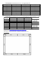
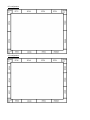
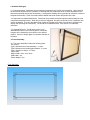
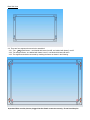
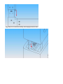
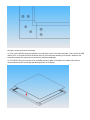
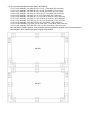
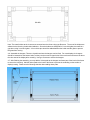
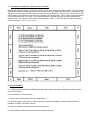
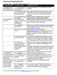
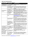
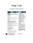
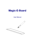
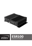
520 Shepherd Drive, TX 75042, USA Tel 1-800-624-4289 (US toll free) or 1-972-272-7555 Fax 972-272-7501 Email [email protected]
OPTIR Touch Fixed-Size Model User’s Manual
Contents:
1. The Components
2. Standard Sizes
3. Available Packages
4. Frame Assembly
5. Custom Size Configuration – How to make it re-sizable
6. Driver Installation
7. Touch Screen Functions
8. Setting and Options
9. Troubleshooting and Technical Support
Update August 18, 2009
1. The Components: All measurements are in mm, 1 mm is approximately 0.04”.
•
Transmitter
Length
Receiver
Length
IRT-31
161.2
IRR-31
161.2
IRT-37
192.4
IRR-37
192.4
IRT-40
208
IRR-40
208
IRT-46
239.2
IRR-46
239.2
IRT-48
249.6
IRR-48
249.6
IRT-49
254.8
IRR-49
254.8
IRT-51
265.2
IRR-51
265.2
IRT-56
291.2
IRR-56
291.2
IRT-64
332.8
IRR-64
332.8
Corner
Length
Controller
Length
IRC-00
35.4
IRM-64
332.8
A universal external power adapter is included. All circuit boards are 32 mm wide and 9 mm high.
2. Standard Sizes: All measurements are in mm, 1 mm is approximately 0.04”. Maximum tolerance = +/- 2mm.
Diagonal Size Typical Display Area
Active Area
PCB Outside Area
Frame Size
16:9 ratio
26”
576 x 324
582.4 x 332.8
653.2 x 403.6
657.2 x 407.6
32”
709 x 399
702 x 400.4
772.8 x 471.2
776.8 x 475.2
37”
820 x 461
821.6 x 462.8
892.4 x 533.6
896.4 x 537.8
40”
886 x 499
889.2 x 504.4
960 x 575.2
964 x 579.2
42”
930 x 524
930.8 x 525.2
1001.6 x 596
1005.6 x 600
46”
1019 x 573
1024.4 x 577.2
1095.2 x 648
1099.2 x 652
47”
1041 x 586
1040 x 587.6
1110.8 x 658.4
1114.8 x 662.4
50”
1107 x 623
1118 x 624
1188.8 x 694.8
1192.8 x 698.8
52”
1152 x 648
1154.4 x 650
1225.2 x 720.8
1229.2 x 724.8
60”
1329 x 748
1331.2 x 748.8
1402 x 819.6
1406 x 823.6
65”
1439 x 810
1430 x 806
1500.8 x 876.8
1504.8 x 880.8
Custom sizes can be arranged. Maximum size 66” x 66” (1680 x 1680 mm). For larger size, please use our
Resizable Models http://www.magictouch.com/IR_screen_resizable.html.
USB interface. Resolution 4096 x 4096. Compatible with Windows, Mac, Linux.
26” configuration:
32” configuration:
37” configuration:
40” configuration:
42” configuration:
46” configuration:
47” configuration:
50” configuration:
52” configuration:
60” configuration:
65” configuration:
3. Available Packages:
3.1. Components Only: Customers can purchase the components only for their own integration. Upon receiving
the active area dimensions from customer, we will assemble the components to be as close as possible to the
dimensions specified and test the functionality. A configuration drawing will be generated for customer to follow to
complete the assembly. Each circuit board will be labeled with serial number and packed into a box.
3.2. Segments are unassembled frames. Customers can purchase the frame segments which already have the
components assembled inside. When they receive the segments, they will just need to join the 4 segments with
corners as labeled. They can also add a piece of glass or Plexiglas to the back of the frame for protecting the
display and optimizing the functionality. The IR filter is included with frame. See section 4 for assembly
instruction.
3.3. Assembled Frame: The IR touch screen is fully
assembled as shown in the following picture, except the
hangers will be installed by the customer to the desired
position. A piece of temper glass is mounted at the back of
the frame.
4. Frame Assembly:
4.1. The frame assembly includes the following parts: The screws:
Type A Screws for the frame assembly - 3 x 4mm.
Type B Screws for the backing glass holders - 3 x 6mm.
Type C Screws for hanger - 3 x 8mm.
Velcro Pads.
Rubber Pads - 5mm, 3mm, 2mm.
USB Cable x 1pc.
Power adapter x 1pc.
Front Side View:
Back Side View
4.2. There are four segments that need to be assembled:
4.2.1. Two
shaped frames – one labeled with letters A and B, one labeled with letters C and D.
4.2.2. Two straight frames - one labeled with letters A and C, one labeled with letters B and D
4.2.3. The segments should be connected by matching the letters as shown in the following:
Important: Make sure the pins are plugged into the female connector correctly. Do not bend the pins.
Align the pins to connector carefully, do not apply excessive force.
Use type A screws to secure the assembly.
4.3. Plug in the USB cable and power adapter to the right-lower corner of the frame assembly. Then connect the USB
cable to a PC. If the yellow LED first blinks then stays on, that means the assembly is successful. Otherwise, the
connections between the segments may need to be checked and adjusted.
4.4. The OPTIR Touch can now work as is, but adding a piece of glass or Plexiglas in the middle of the frame is
recommended for better functionality and added protection to the display.
4.5. The recommended glass sizes are listed in the following:
4.5.1. For 26” assembly: 1/8” thick, 23 5/16 x 13 1/2” ( 3 mm thick, 592 x 343 mm).
4.5.2. For 32” assembly: 1/8” thick, 28 1/16 x 16 1/8” (3 mm thick, 712 x 411 mm).
4.5.3. For 37” assembly: 1/8” thick, 32 3/4” x 18 5/8” (3 mm thick, 832 x 473 mm).
4.5.4. For 40” assembly: 1/8” thick, 35 7/16” x 20 1/4” (3 mm thick, 900 x 514 mm).
4.5.5. For 42” assembly: 1/8” thick, 37 x 21 1/16” (3 mm thick, 941 x 536 mm).
4.5.6. For 46” assembly: 1/8” thick, 40 11/16 x 23 1/8” (3 mm thick, 1033 x 587 mm).
4.5.7. For 47” assembly: 1/8” thick, 41 7/16 x 23 9/16” (3 mm thick, 1053 x 598 mm).
4.5.8. For 50” assembly: 3/16” thick, 44 1/2 x 25 1/16” (5 mm thick, 1130 x 637 mm).
4.5.9. For 52” assembly: 3/16” thick, 45 7/8 x 26” (5 mm thick, 1165 x 660 mm).
4.5.10. For 60” assembly: 3/16” thick, 52 7/8” x 29 15/16” ( 5 mm thick, 1343 x 760 mm).
4.5.5. For 65” assembly: 3/16” thick, 56 11/16 x 32 1/8” (5 mm thick, 1440 x 816 mm).
After the glass is placed in position, a set of holders should be screwed or adhered to the back of the frame to
hold the glass. Note: Using temper glass is highly recommended.
Note: The metal holders at the 4 corners are screwed onto the frame using type B screws. The rest of the holders are
adhered to the frame by double-sided adhesive. Since the holders are designed for 5 mm thick glass, there will be a
gap when using 3 mm thick glass. A 2 mm thick tape should be added between the holder and the glass to prevent
the glass from moving.
4.6. Assemble the hangers: There are 4 positions where the hangers can be fixed. For most displays, the hangers
should be inserted into the bottom holes, but they can be moved to upper holes if the touch screen seems to be above
the view area of the display after mounting. Use type C screws to secure the hangers.
4.7. After finishing the assembly, you may add the Velcro pads to the hangers and lower part of the back of the frame
to secure the mounting. Add the rubber pads to the back of the frame to prevent the scratching on the surface of
display housing. Please see the following sketches about adding those pads:
5. Custom Size Configuration – How to make it re-sizable
Although this model is named as “Fixed Size” model, it still can be re-sized with certain limitations. The rule of thumb
is all the parts with part number that can be evenly divided by 4 are re-sizable parts, which can be assembled in any
sequence. For those parts with part number that cannot be evenly divided by 4, only one piece can be used on each
side, and they must be placed next to the corner as shown in the following figure. The 3 corners must be assembled
in the positions as shown in the figure. The controller IRM-64B is required, and a IRT-64 is also required at the
opposite frame. The maximum active area can be assembled is 1679.6 x 1679.6 mm which includes the following
parts on each side: 1 x 51 + 3 x 48 + 2 x 64.
6. Driver Installation:
6.1. A USB controller and Windows 2000/XP/Vista driver are included. Mac driver is included only when the Mac
version is purchased.
6.2. Insert the driver CD into CD Rom.
6.3. Click to select USB controller, then click install button.
6.4. When prompted for plug into the controller, plug the controller into USB port. Windows shows “found new
hardware” message. Click OK to continue.
6.5 When prompted for restart the Windows, click OK to reboot.
6.6. After Windows is rebooted, two new icons are created on desktop.
Touch USB
Swap Button
At this point, the LED on the controller should be on and IR screen should respond to touch, but the position
of touch is not accurate until the screen is calibrated. If the IR screen is not responding to touch, unplug and replug in the USB cable to re-initiate the controller.
6.7. Double click Touch USB icon to open touch control panel.
6.8. Click the calibration button, choose either 5 or 25 point calibration then click ‘GO!’ Touch the center of each
Circle and hold for 2 seconds to complete the calibration.
6.9. Repeat the calibration if necessary. Click OK to close the window.
6.10. If you have Vista OS, there are the options of using touch screen as mouse or tablet by clicking the desired
button in Touch USB control panel. In tablet mode, the touch response is usually slower.
7. Touch Screen Functions:
7.1. Screen touched = left mouse button clicked
7.2. Touch down and drag = left mouse button held down and dragged
7.3. Tap twice = left mouse button double clicked
7.4. Swap Button: Select ‘once’ to right-click for one touch, or ‘always’ to always right-click. Select minimize to
reduce to system tray. Click in tray as a shortcut!
8. Settings and Options:
8.1. Mouse speed: Control the tracking speed of mouse cursor.
8.2. Double click speed: Control the time interval between two clicks to activate a double click. Slow speed
makes double click easier. Test the double click by tapping the K logo twice. If successful, the logo rotates.
8.3. Lift Off: When this option is enabled, the click is activated when touch is lifted away from the touch screen.
This mode is very useful for clicking hyperlinks, such as Internet browser, or programs that use “mouseover” function. However, it is impossible to drag or draw in this mode.
8.4. Beep: Enable/disable an audio beep when touching the touch screen.
8.5. Move only: Touching and dragging only moves the mouse cursor without performing a click. This option is for
those who have an optional click pen (currently unavailable).
8.6. Hide cursor: Makes the cursor invisible (preferred for some applications).
8.7. Uninstall: Click to uninstall the driver.
8.8. Default setting: Return the speeds and options to the original settings.
9. Troubleshooting and Technical Support:
9.1. Make sure the driver was installed first before the USB controller is plugged into a USB port.
9.2. Make sure the power supply is plugged into the controller (next to USB cable connection).
9.3. Make sure the controller always plugged into the same USB port.
9.4. Make sure the sensors are leveled, and the corners are right angled.
If the problem persists, contact KEYTEC’S tech support:
Email to [email protected] or call 972-272-7555 (8:30AM to 5:00PM CST M-F).