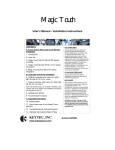
1
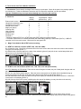
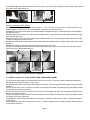
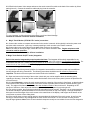
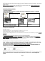
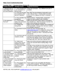
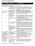
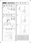
Magic Touch
User’s Manual - Installation Instructions
CONTENTS:
FCC COMPLIANCE
A. Touch Screen and Touch Monitor Installation
1. Introduction.
2. Parts list.
3. Magic Touch Add-On Kits (KTMT series) mounting.
3.1. KTMT-1214, 1500, 154W.
3.2. KTMT-1315, 1700, 1900, 1921.
3.3. KTMT-1700W, 1900W, 2200W, 2400W.
4. Magic Touch Monitor (KTSC, KTLC series) connection.
5. Magic Touch Built-In Kits (KTT series) integration.
B. Controller and Driver Installation
1. Controller installation
2. Install driver on Windows OS
2.1. USB controller
2.2. Serial RS232 controller
3. Install driver on Mac OS
This equipment has been listed and found to comply
with the limits for a Class B digital device, pursuant
to Part 15, Subpart B of FCC Rules. This equipment
generates, uses, and can radiate radio frequency
energy. If not installed and used in accordance with
the instructions, it may cause interference to radio
communications. The limits are designed to provide
reasonable protection against such interference in a
residential situation. There is no guarantee that
interference will not occur in a particular installation.
CE and RoHS COMPLIANCE
This equipment has been tested, analyzed and found
to comply with CE and RoHS requirements.
DISCLAIMER
The material in this document is for an informational
purpose and is subject to change without notice.
The manufacturer assumes no responsibility for
errors or omissions in this document. Nor are any
liability assumed for any damages from the use of
this product and the information contained in this
document. All mentioned product names herein are
registered trademarks of the respective companies.
All rights reserved. No part of this document and
the software provided with the product may be
reproduced or modified without permission of
the manufacturer.
C. Settings and Options
D. Touch Screen Functions
E. Important Information
1. Helpful Notes
2. How to take care of your touch screen products.
F. Troubleshooting & Technical Support.
G. Warranty information & Return Policy.
KEYTEC, INC.
www.magictouch.com
Revision M-041210
A. Touch Screen and Touch Monitor Installation
1. Introduction: Please identify the Magic Touch model you purchased. Check all the parts in the package against
the following list. Follow the installation instruction only for the specific model that you have purchased.
Improper installation may cause permanent damage not covered by the warranty.
2. Parts List:
Add-On
Touch Monitor Built-In
(KTMT)
(KTSC/KTLC) (KTT)
External touch screen
1
0
0
Hangers & accessories* (set)
1
0
0
Integrated touch monitor
0
1
0
Internal touch screen
0
0
1
Magic pen (stylus)
1
1
1
Cleaning cloth
1
1
1
User’s manual
1
1
1
Installation CD
1
1
1
Warranty card
1
1
1
Controller **
1
1
1
* Notebook models (KTMT-1214, KTMT-1500, and KTMT-154W) do not have hangers.
** Controller is either a box or a board (SB model) with USB cable (USB-XD) or serial cable (ProE-X). USB5-XD
controller is for 5-wire touch screen - black color box with green LED.
3. Magic Touch Add-On Kits (KTMT series) mounting:
3.1. KTMT for notebook computer (KTMT-1214, 1500 and 154W):
3.1.1. Open the cover. Remove the protective film on the touch screen and mount the touch screen to the notebook
using the Velcro straps (picture 1).
3.1.2. Buckle the horizontal straps to the back of the notebook (picture 2) and pull the two vertical straps down and
adhere them to the horizontal strap (picture 3).
Continue to Section B. Controller & Driver Installation.
1
2
3
3.2. KTMT for 4:3 ratio monitors (KTMT-1315, 1700, 1900, 1921 with plastic frame):
3.2.1. For Mounting on LCD monitor: There are two sets of hangers included; one pair of hard plastic hangers and one
pair of Velcro hangers.
3.2.1.1. You may use the plastic hangers. Place the touch screen panel on a flat table with the backside facing up.
Screw two hangers into the back of the panel using the top screw holes on the hanger (picture 1).
3.2.1.2. Adhere two Velcro strips provided on the top of the display as indicated by the arrows in picture 2. Mount the
touch screen to the display (picture 3).
3.2.1.3. If the top of the touch screen is blocking the view area of the display, you may raise the touch screen by
adding the rectangular foam pad underneath the hangers (picture 4).
4
1
2
3
3.2.1.4. Alternatively, you may use the Velcro hangers (picture 5). The soft surface of the Velcro faces up when
fastening them with the screws to the frame. Mount the touch screen to the display and press the Velcro firmly (picture
6).
Page 1
3.2.1.5. Must apply the Velcro at bottom of the screen (picture 7) to secure the mounting. Use the cable clips to secure
the touch screen cable (picture 8).
7
5
6
8
Continue to section B. Controller & Driver Installation.
3.2.2. For mounting on CRT monitor:
3.2.2.1. Measure the top frame of the monitor (picture 1). If it is 1.5 inches (3.8 cm) or less, use the top holes on the
plastic hangers to screw into the touch screen panel. Otherwise, use the bottom holes.
3.2.2.2. Place the touch screen panel on a flat table with the backside facing up. Screw two hangers into the back of
the panel (picture 2).
3.2.2.3. Hang the touch screen onto the monitor in center position. Use a pencil to mark the hangers’ position on top
of the monitor (picture 3).
3.2.2.4. Remove the touch screen from the monitor. Adhere two pieces of Velcro strips (provided) onto the top of the
monitor near the pencil marks (picture 4).
3.2.2.5. Mount the touch screen panel as close to the monitor as possible with the hangers aligned to the Velcro strips
(picture 5).
3.2.2.6. Press down the hangers firmly to fasten the Velcro strips (picture 6).
3.2.2.7. You must apply the Velcro at bottom of the screen (picture 7) to secure the mounting. Use the cable clips to
secure the touch screen cable (picture 8).
4
1
2
3
5
6
7
8
It is very important to follow the above procedures to avoid accidental damage.
Continue to section B. Controller & Driver Installation.
3.3. KTMT for widescreen display (KTMT-1700W, 1900W, 2200W, 2400W)
3.3.1. There are two hangers to be assembled on the top of the frame. There are 4 ways to assemble the hangers
depending on the top frame width of your monitor.
3.3.2. Screw through the top 2 holes of the hangers to the frame. This mounting should be suitable for most monitors
(picture 1).
3.3.3. If the top frame of your monitor is very wide, you can drop touch screen by screwing through the bottom 2 holes
of the hangers to the frame (picture 2).
3.3.4. If the top frame of your monitor is narrow, you can turn the hanger over and screw through the top holes of the
hanger to the frame (picture 3).
3.3.5. If the top frame of your monitor is extremely narrow, turn the hanger over and screw through the bottom holes of
the hanger to the frame (picture 4).
3.3.6. Adhere the Velcro pads to the bottom of the hangers. Remove the wax film from Velcro. Unbuckle the bottom
Velcro straps.
3.3.6. Align and hang the touch screen on the monitor. Press the hangers down to make the Velcro adhere to the top
of the monitor (picture 5).
Page 2
3.3.7. Buckle the bottom Velcro straps and secure the touch screen's flex cable to the back of the monitor by Velcro
pads (picture 6). Connect the extension cable and plug it into the controller.
1
2
3
4
6
5
It is very important to follow the above procedures to avoid accidental damage.
Continue to section B. Controller & Driver Installation.
4.
Magic Touch Monitor (KTSC & KTLC series) connection:
4.1. Connect the monitor to computer as instructed in the monitor’s manual, which typically involves the power cord
and video cable connection. Ignore any contents pertaining to touch screens in the monitor’s manual.
4.2. Connect the touch screen cable from the back of the monitor to the controller.
Note: If the cable is not long enough, contact KEYTEC for a custom extension cable. Regular telephone cable
cannot be used for extension.
Continue to section B. Controller & Driver Installation.
5. Magic Touch Built-In Kit (KTT series) integration:
Built-in kits must be integrated by experienced technicians. The integrator will be solely responsible for any
damage to the monitor and touch screen kit. Physical damage to the touch screen is not covered by the warranty. For
all standard LAM and CAF1 models, the flex tail should be on the left and its alignment mark (“white dot”) should
match the one on the extension cable. The display needs to have minimum of 3 mm or 1/8” space inside for
touch screen integration.
It is impossible to provide a general guideline for integration because different monitor models may have different
housing design and wiring connections. The following procedures should be used for reference purpose only:
Important: Test both touch screen panel and monitor before the installation.
5.1. Open and remove the housing of the monitor (check with your monitor supplier about the warranty policy
regarding to this step). Clean the monitor surface and the back of the touch screen panel (remove the protective film
on touch screen).
5.2. It is very important to center the touch screen panel to the opening of the monitor’s front frame, so that the edges
of the frame will not contact the active area of the touch screen to prevent shorts caused by constant touching (preload). The edges of the frame should rest on the clear insulation border of the touch screen. Depending on the
structure of the frame, foam strips and washers may be needed to add space for preventing shorts.
5.3. For service purpose, the touch screen should be removable from the monitor. Therefore, it is not recommended to
use double side tape or permanent adhesive to mount the touch screen on top of the display. Use high temperature
duct tape to mount the edges of the touch screen to the metal frame of the display. Add support at the bottom of the
touch screen to prevent it from sliding down.
5.4. If the monitor does not have enough space to accommodate the thickness of the touch screen, do not force the
housing to close because it may damage both the touch screen and monitor. Do not force the mounting screws
beyond finger tightness. Note: Slim LCD and notebook computers usually are not suitable for touch screen integration.
Page 3
5.5. Pull the touch screen cable out from the back of the monitor. Replace the connector if necessary – make sure the
wiring is correct.
Note: If the cable is not long enough, contact KEYTEC for a custom extension cable. Regular telephone cable
cannot be used for extension.
Continue to section B. Controller & Driver Installation.
B. Controller and Driver Installation
1. Controller Installation:
There are three types of controller box– USB-XD, USB-5 & ProE-X as labeled on the controller. The SB model
controller does not have a box.
The USB-XD or USB-5
The ProE-X controller should be
controller should be plugged
plugged into the serial port (Com1
into the USB port when
or 2) when the computer is
instructed by the driver
powered off.
installation steps.
For the models come with an extension
cable, connect it between touch screen
and controller with white dots aligned.
Connect controller to
computer as instructed
above.
Plug the touch screen cable into the
controller box.
2. Install driver on Windows OS:
2.1. USB Controller:
USB-XD controller (Win 7, Vista, XP, 2000, ME, 98, Mac 9.2.2-10.6.x, Linux)
USB-5 controller (Win 7, Vista, XP, 2000, Mac 9.22-10.6x, Linux)
If there is a previous Magic Touch driver or other manufacturer’s touch screen driver installed in your system, uninstall
them first.
All Windows and Linux drivers are included on one CD, and can be downloaded at
www.magictouch.com/support_usb_xd.html. Multi Monitor setup and examples are under the folder MultiMonitor
driver. Mac driver CD is included only if you have ordered Mac version (USB-M or USB-WM) – extra charge applies.
Mac user: please see Sec. 3. for instructions
Linux user: please see readme file in Linux folder for setup instructions.
2.1.1. Must log-on with administrator’s password for Windows 7, Vista, XP, 2000)
2.1.2. Insert the setup CD. The setup window will display on the desktop. Click to select USB controller. Then click
Install. (Windows may require your permission to allow setup to run.) Note: If setup window does not open, the CDRom’s autorun may be disabled. Click START\RUN to run the setup from the driver CD.
2.1.3. When the system prompts “please plug in the Magic Touch USB to USB port”, plug in the controller. After
Windows has found the new hardware, click OK to continue.
2.1.4. When “must reboot Windows to complete the installation” shows, click OK to reboot.
2.1.5. After Windows is rebooted, two new icons are created on desktop.
Touch USB
Swap Button
2.1.6. Double click Touch USB icon to open touch control panel.
2.1.7. Click the Calibration button, choose either 5 or 25 point calibration and click ‘GO!’ To calibrate, touch and hold
the center of each circle for a full second before lifting your finger. The circle will then progress to the next one until
all 5 or 25 have been touched. Use the stylus to perform calibration for better accuracy. See C. Settings and
Options.
Page 4
2.2. Serial RS232 Controller
ProE-X Controller (Win Vista, XP, 2000, ME, 98, 95, NT4.0, Linux.)
If there is a previous Magic Touch driver or other touch screen’s driver installed in your system, uninstall them first.
All Windows and Linux drivers are included on one CD, and can be downloaded at
www.magictouch.com/support_proe_x.html. For NT 4.0 & Linux user: please see readme file for setup instructions.
2.2.1. MUST log-on with administrator’s password for Vista, XP, 2000 & NT 4.0.
2.2.2. Insert the setup CD. The setup window will display on the desktop. Click to select ProE controller. Then click
Install. (Windows may require your permission to allow setup to run.) Note: If setup window does not open, the CD
Rom’s autorun may be disabled. Click START\RUN to run the setup from the driver CD.
2.2.3. When the system prompts “must reboot Windows to complete the installation”, plug in the ProE controller to a
“free” Com port*, click OK to reboot. *Free Com port means there is no other device configured to use this Com port.
2.2.4. After reboot, the Detect New Hardware Wizard opens. Click next and continue anyway at Digital Signature
prompt.
2.2.5. Two new icons are created on desktop.
Touch RS232
Swap Button
2.2.6. Double click TouchRS232 to open touch control panel.
2.2.7. Click the Calibration button, choose either 5 or 25 point calibration then click ‘GO!’ Touch and hold the center
of each circle for a full second to complete the calibration. Use the stylus for better accuracy. Repeat the
calibration if necessary. Click OK to close.
See C. Settings and Options.
3. Install driver on Mac OS:
For Macintosh with USB port (a quick guide file is included in the CD)
Plug in the controller to USB port and plug in the touch screen cable to controller.
3.1. Insert the installer CD*. Double click to open the Magic Touch CD icon.
3.2. There are 7 folders for OS 9.2.x, 10.1.x, 10.2.x, 10.3.x, 10.4x, 10.5x & 10.6x.
3.3. Open the folder that matches your OS version. (see Apple->About this Mac)
3.4. Double-click MagicTouch icon to run installation. If a LOCK icon appears on the lower-left corner, click and type in
the administrator’s password.
3.5. After installation is completed, restart the computer.
3.6. Calibrate the screen: For OS 10.x, click Go\Application\Magic Touch Utility\Magic Touch. For OS 9.x, click
Apple\Control Panel\Magic Touch Utility\Magic Touch. Before entering the calibration screen, you will be prompted for
“lift-off” mode selection. (This appears as a check box in OS X) In lift-off mode the mouse click is activated when touch
is lifted from the screen. Please see quick guide for details. Once the selection is made, the calibration screen is
shown. Touch the centers of the X or circle (depending on the OS**) with stylus provided (for better accuracy) to
complete the calibration. Check the accuracy, repeat if necessary. Press cancel to exit.
* The Windows and Linux drivers are normally not included with the touch screen sold as Mac version, but they can be
downloaded at www.magictouch.com/support_usb_xd.html for free.
** 9.2-10.4 has 3-X calibration points without multi-monitor option. 10.5-10.6 has 5/25-circle calibration points with
multi-monitor option.
C. Settings and Options of Magic Touch Control Panel (Windows version):
1. Mouse or Tablet: When using Windows 7 or Vista, there are options of choosing tablet or mouse mode. When
tablet mode is selected, you will be able to use Windows tablet gestures. The response speed is relatively slower in
tablet mode than in mouse mode.
2. Mouse speed::Control the tracking speed of mouse cursor.
3. Double click speed: Control the time interval between two clicks to activate a double click. Slow speed makes
double click easier. Test the double click by tapping the K logo twice. If successful, the logo rotates.
4. Lift Off: When this option is enabled, the click is activated when touch is lifted away from
Page 5
the touch screen. This mode is very useful for clicking hyperlinks, such as Windows icon set with single-click open,
Internet browser, or programs with “mouseover” event. However, it is impossible to drag or draw in this mode.
5. Beep: Enable/disable an audible beep when a touch is sensed. Customize the beep’s pitch and duration under
‘Beep Options.’
6. Move only: Touching and dragging moves the mouse cursor without performing a click. This mode was designed for
an optional click pen (currently unavailable).
7. Hide cursor: Makes the cursor invisible (preferred for some applications).
8. Uninstall: Click to uninstall the driver. Correct password needed. (magictouch is the default password).
9. Default setting: Return the speeds and options to the original settings.
D. Touch screen functions:
1. Screen touched = left mouse button clicked
2. Touch down and drag = left mouse button held down and dragged
3. Tap twice = left mouse button double clicked
4. Swap Button: Select ‘once’ to right-click on next touch only, or ‘always’ to right-click on every touch. Select minimize
to reduce to system tray as a shortcut!
Note: Using tablet mode in Windows 7 and Vista, touch and hold will activate right-click.
E. Important Information
1. Helpful Notes:
1.1. Place the monitor at an easy-to-touch position and avoid direct strong lighting to reduce glare on the screen.
1.2. It is easier to use the stylus for clicking smaller icons; dragging and drawing (apply constant pressure when
drawing).
1.3. Make one-point touch only. Do not lean your hand on the screen or touch it with more than one finger or stylus.
1.4. Increase the size of icon and menu bar for easy touch.
1.5. If double-click is difficult, change to single click in ‘Folder Options’.
2. How to take care of your Magic Touch product:
2.1. DO NOT touch the screen with hard, sharp objects.
2.2. DO NOT hit or drop the screen.
2.3. DO NOT spray any liquid directly to the screen. Clean the screen with soft cloth or paper towel dampened with
cleaning solution, such as Windex, alcohol.
2.4. DO NOT alter or substitute any parts.
2.5. Put the screen into the original packaging for storage and transportation.
Failure to handle and use this product properly will negate the warranty.
F. Troubleshooting & technical support:
Troubleshooting guide is on the driver CD (except for Mac version) and also available at
www.magictouch.com/guide.html Request support online at www.magictouch.com/techsupport.html or send e-mail to.
[email protected] Please include the information about Magic Touch model, driver version installed, your
operating system and the nature of the problems encountered. You may also call 972-272-7555 (9-5/ M-F Central
Time) or contact your local authorized dealer for assistance.
G. Warranty Information & Return Policy:
Warranty information can be found on the driver CD and also available at www.magictouch.com/warranty.html.
Register to activate your warranty online at www.magictouch.com/WarrantyReg.html or send in the registration card at
back cover of this manual.
If you need to return the product, you must first contact KEYTEC’S tech support & RMA department to get a return
authorization number (RMA#). Please email to [email protected] or call 972-272-7555. The product must be
packed with sufficient protection, insured for full value, and shipped with freight prepaid.
If the product is purchased from a KEYTEC dealer, please check with your dealer directly about their return policy.
Page 6
KEYTEC Touch Screen Warranty Registration Card
To assure your warranty rights, complete and send this warranty card by
1. mail to KEYTEC, INC. 520 Shepherd Drive, Garland, TX 75042, USA, or
2. scan and email to [email protected], or
3. copy and fax to 972-272-7501, or
4. register on-line at http://www.magictouch.com/WarrantyReg.html
Privacy Policy: We do not disclose the following information to any third party. The information hereafter will be used
strictly for the purpose of warranty service only.
Name: _______________________ Email: __________________________
Organization: __________________________________________________
Address: _____________________________________________________
_____________________________________________________________
Tel: __________________________ Fax: ___________________________
Product Purchased (please check): ____ Add-On Touch Screen (KTMT)
___ Touch Monitor (KTSC or KTLC), ___ Built-In Touch Screen (KTT)
___ View Touch ___ OPTIR Touch or Others, please specify: _____________
Part Number: __________________ Serial Number: _________________
Purchased from: ____________________________ Date: ____________
EXTENDED WARRANTY: I would like to purchase extended warranty, please have a sales rep contact me by
__ email, __ phone, or __ fax.
Warranty Information: Please refer to http://www.magictouch.com/warranty.html
HOW TO OBTAIN WARRANTY SERVICES:
1. You must first notify KEYTEC's technical support dept. by sending e-mail to [email protected] or fax to 972272-7501 or calling 972-272-7555 to report the problem.
2. If the technical support personnel has determined that your product needs to be serviced, you will be given a RMA#
(Return Merchandise Authorization Number) for sending your product in for service.
3. You must deliver the product freight prepaid in the original package or package with equal degree of protection to
the authorized service station as instructed by technical support department. The RMA# must be clearly marked
outside of the package. Your return address must be included.
4. If the product is out of the warranty, you will be quoted for the replacement or repair cost. No work will be performed
until your approval on all the charges is confirmed.
WHAT'S NOT COVERED?
1. Products that have been previously altered, repaired or serviced by unauthorized personnel.
2. Serial number on the products has been altered or removed.
3. Cosmetic damages and physical damages. Damages due to improper installation, operation or connection to
improper voltage supply.
4. Any damages due to misuses, abuses, negligence, unauthorized modifications, accidents and acts of God.
5. Those products which were sold AS IS or WITH ALL FAULTS.
Join KEYTEC'S Facebook for quick access to updates, events and special deals.
Page 7