1
BROOKFIELD R/S-CPS+ RHEOMETER
Operating Instructions
Manual No. M/01-213-A0706
SPECIALISTS IN THE
MEASUREMENT AND
CONTROLOFVISCOSITY
with offices in:
Boston•Chicago•London•Stuttgart•Guangzhou
BROOKFIELD ENGINEERING LABORATORIES, INC.
11CommerceBoulevard,Middleboro,MA02346USA
TEL 508-946-6200
FAX 508-946-6262
Brookfield Engineering Labs., Inc.
or 800-628-8139 (USA excluding MA)
INTERNEThttp://www.brookfieldengineering.com
Page M01-213-A0706
Contents
I. General Description................................................................................................ 4
I.1 Use of the Rheometer..................................................................................... 4
I.2 Measuring Principle......................................................................................... 4
II. System Configuration............................................................................................. 5
II.1 R/S-CPS+ Rheometer..................................................................................... 6
II.2 Measuring Devices.......................................................................................... 8
II.3 Computer System............................................................................................ 8
III. Instrument Installation........................................................................................... 9
III.1 Mounting the Instrument.................................................................................. 9
III.2 Electrical Connections..................................................................................... 9
III.2.1 Temperature Sensor............................................................................ 10
III.2.2 AC Adapter.......................................................................................... 10
III.2.3 Printer Connection.............................................................................. 10
III.2.4 Computer Connection......................................................................... 11
III.3 Connecting the Temperature Control Device................................................. 11
III.3.1 Connecting a Bath/Circulator.............................................................. 11
III.3.2 The Peltier Temperature Control Device............................................. 12
IV.
Environment, Handling, Cleaning and Maintenance......................................... 13
IV.1 Operating Environment.................................................................................. 13
IV.2 Handling........................................................................................................ 13
IV.3 Cleaning........................................................................................................ 13
IV.4 Maintenance.................................................................................................. 14
V. Measuring Systems.............................................................................................. 15
V.1 Inserting and Adjusting the Measuring Elements.......................................... 15
V.2 Filling the Measuring Systems, Measuring.................................................... 17
VI.
Operation and Menu System............................................................................... 18
VI.1 Keyboard....................................................................................................... 19
VI.2 Menu System of R/S-CPS+ Rheometer........................................................ 21
VI.3 Selecting from Lists ...................................................................................... 22
VI.4 Input of Numerical Values and Alphanumeric Texts ...................................... 23
VI.5 Menu Entries (MAIN menu) .......................................................................... 24
VI.5.1MAIN menu → Single Measurement ................................................. 24
VI.5.2MAIN menu → Program Measurement .............................................. 27
VI.5.3MAIN menu → Remote ....................................................................... 29
Brookfield Engineering Labs., Inc.
Page M01-213-A0706
VI.6
VI.7
VI.8
VI.5.4MAIN Menu → Utilities ........................................................................ 30
VI.5.5MAIN Menu → Configuration .............................................................. 30
Menu Entries in the Utilities Menu ................................................................ 30
VI.6.1Utilities → Zero calibration .................................................................. 30
VI.6.2Utilities → Edit Program ...................................................................... 31
VI.6.3Utilities → Print Programs ................................................................... 35
VI.6.4Utilities → Measuring Systems ........................................................... 35
VI.6.5Utilities → Print Memory ..................................................................... 36
VI.6.6Utilities → Clear Memory .................................................................... 37
VI.6.7Utilities → Measure Temperature ....................................................... 37
Menu Entries of the Configuration Menu....................................................... 38
VI.7.1Configuration → Output Mode............................................................. 38
VI.7.2Configuration → MeasCount Mode..................................................... 39
VI.7.3Configuration → MeasCount=0........................................................... 39
VI.7.4Configuration → Time/Date................................................................. 39
VI.7.5Configuration → RS232 Parameters................................................... 40
VI.7.6Configuration → Language.................................................................. 41
VI.7.7Configuration → Service...................................................................... 42
Serial Data Transfer via the RS232 Interface................................................ 42
VII. Measuring.............................................................................................................. 44
VII.1 Measuring in Manual Operation.................................................................... 44
VII.2 Measuring in Remote Operation.................................................................... 44
VIII. Technical Data....................................................................................................... 45
IX. Guarantee.............................................................................................................. 47
Appendix A.................................................................................................................... 48
A.1 Data Sheets of Standard Measuring Systems .............................................. 48
A.2 Error Messages............................................................................................. 49
A.3 Pin Assignment of the Serial Data Cable....................................................... 51
A.4 Requirements to the AC Power Connecting Cables...................................... 52
A.5 Language Cross Reference........................................................................... 53
Appendix B: Calibration Check Procedure................................................................ 55
Appendix C: Warranty and Repair Service................................................................. 63
Brookfield Engineering Labs., Inc.
Page M01-213-A0706
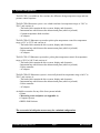
I. General Description
I.1
Use of the Rheometer
The R/S-CPS+ Rheometer is a good choice for use in quality control, product development and
research environments, especially where small sample volume and minimum instrument service requirements are important . It allows the rheological characterization of both Newtonian
and non-Newtonian fluids. The instrument benefits include a broad measurement range, testing
for Yield properties, and the ability to measure flow properties of fluids with delicate structures.
I.2
Measuring Principle
The R/S-CPS+ Rheometer is a rotational controlled stress instrument with geometries (cones
and plates) conforming to DIN specification 53-018.
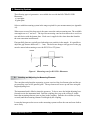
The geometry is directly connected to the motor shaft. A current is applied to the Rheometer
motor, and the resulting speed (RPM) is measured with an optical encoder directly connected
to the motor shaft. The applied torque is converted to shear stress (Tau), and the RPM is converted to shear rate (D) by the instrument electronics.
This is the controlled shear stress or CSS mode. The user defines the stress value and the instrument maintains that value.
The R/S CPS+ can also operate in controlled shear rate (CSR) mode where a feedback loop is
used: A speed or shear rate is entered by the user. The instrument ramps motor current up or
down (depending on the starting speed. If the instrument is at 0 rpm, and set point is 500 RPM
current is ramped up. If speed is 1000 RPM, current is ramped down). Speed is constantly
measured by the optical encoder and once the set point speed is achieved, minor adjustments in
the current applied to the motor are made, to maintain that speed.
Brookfield Engineering Labs., Inc.
Page M01-213-A0706
II. System Configuration
The R/S-CPS+ is available in four versions, the difference being temperature range and temperature control ooptions:
The R/S-CPS+ Rheometer system uses a bath/circulator for temperature range of -20°C to
250°C and consists of:
- The head which contains the drive system, display and electronics
- Instrument base which houses the measurement plate (which is jacketed)
- Constant temperature bath circulator
- AC adapter
The R/S-CPS+ P1 Rheometer system has peltier plate temperature control for temperature
range of 0°C to 135°C and consists of:
- The head which contains the drive system, display and electronics
- Instrument base which houses the measurement plate (which is jacketed)
- Peltier controller
- AC adapter
The R/S-CPS+ P2 Rheometer system has peltier plate temperature control for temperature
range of 20°C to 180°C and consists of:
- The head which contains the drive system, display and electronics
- Instrument base which houses the measurement plate (which is jacketed)
- Peltier controller
- AC adapter
The R/S-CPS+ E1 Rheometer system is electrically heated for temperature range of 60°C to
250°C and consists of:
- The head which contains the drive system, display and electronics
- Instrument base which houses the measurement plate (which is jacketed)
- Peltier controller
- AC adapter
Available accessories for any of the four systems include:
• Printer
• Measuring cones and plates (see Appendix A)
• Computer system
• RHEO 2000 Software
The accessories in bold print are necessary for a minimal configuration.
Brookfield Engineering Labs., Inc.
Page M01-213-A0706
II.1 R/S-CPS+ Rheometer
The Rheometer head includes:
• Digital control of rotational speed and torque
• Automatic adjustment of control parameters during measurement
• Direct indication of measured and calculated values of speed, torque, shear rate, shear
stress, viscosity, temperature, time
• Internal storage of measured values
• Parallel printer port
• RS232C serial port for connection of a computer
The R/S-CPS+ may be operated from the instrument keyboard or with optional Rheo2000 software running under Windows 2000 or higher.
Brookfield Engineering Labs., Inc.
Page M01-213-A0706
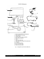
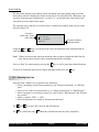
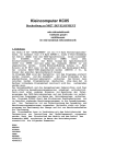
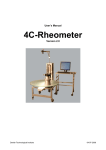
R/S-CPS+ Rheometer
12
1
11
3
2
8
10
4
5
6
7
9
1
2
3
4
5
6
7
8
9
10
11
12
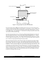
Measuring Head of R/S-CPS+ Rheometer
Measuring Element Coupling
Cooling Flange
Measuring Cone or Measuring Plate
Bottom Measuring Plate
Stand
Height Adjusting Lever
Nonius Micrometer Ring (for fine adjustment)
AC Adapter
DC Connecting Socket
Mains Connection Cable
Data Transmission Cable
Fig. 1: Configuration of the R/S-CPS+ Rheometer
Brookfield Engineering Labs., Inc.
Page M01-213-A0706
II.2 Measuring Devices
The instrument is equipped with a temperature-controlled bottom plate. At least one measuring
cone or measuring plate is required for operation. These rotating elements are not part of the
basic equipment of the R/S-CPS+ Rheometer. They should be ordered based on your application and/or testing requirements.
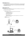
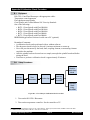
II.3 Computer System
The computer system is optional and provides full control of the Rheometer, data and test program storage, printing of test data and plots etc.
The computer system consists of:
• IBM-compatible PC with the following minimal system requirements:
- CPU Pentium III or better
- 512 MB RAM (main memory),
- 5 GB free hard disk capacity
- Windows® 2000 or higher
- Mouse and keyboard
- 1 RS232c serial port for Rheometer when using R/S-CPS+, two serial ports for
R/S-CPS+ P1, P2 and E1.
• Printer
• RHEO2000 Software
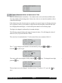
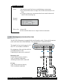
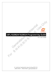
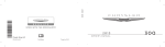
Centronics
Printer when using
R/S-CPS Rheometer
without computer
R/S-CPS Rheometer
RS232 (Data transmission)
PC
LPT1
Printer when using
R/S-CPS Rheometer
remote controlled
Software RHEO 2000
Fig. 2.: Computer System for R/S-CPS+ Rheometer
Brookfield Engineering Labs., Inc.
Page M01-213-A0706
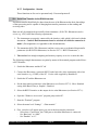
III.Instrument Installation
This chapter covers installation of the R/S CPS+ Rheometer and includes:
- assembly of the R/S-CPS+ Rheometer
- electrical connections
- installation of accessories such as bath/circulator, measuring systems
- tubing connections.
III.1 Mounting the Instrument
The R/S-CPS+ Rheometer must be positioned on an even surface (laboratory bench) such
that there is enough room for easy handling of the instrument. Exposure to direct sunlight
and other heat and cooling sources should be avoided to ensure proper temperature control of
sample test material.
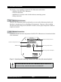
III.2 Electrical Connections
Connections for the electrical components of the R/S-CPS+ Rheometer are located on the back
of the instrument.
Centronics
Interface for Printer Connection
RS232
Interface for Computer Connection
Power
DC
ON/OFF Switch
Pt 100
Connecting Socket for Pt 100
Connecting Socket for AC Adapter
Figure 3: Operating and connecting elements at the back side of the measuring head
All cables from and to the R/S-CPS+ Rheometer must be connected or
disconnected only when the instrument is switched off!
Brookfield Engineering Labs., Inc.
Page M01-213-A0706
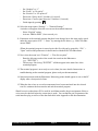
III.2.1 Temperature Sensor
The connecting cable of the temperature sensor Pt 100 is inserted into the socket “Pt100”
at the back side of the R/S-CPS+ Rheometer. The temperature probe is mounted under
the Rheometer plate.
III.2.2 AC Adapter
The AC adapter supplies the R/S-CPS+ Rheometer with power (~16 vdc).
The AC adapter may only be inserted to a socket with proper
grounding. Connect the AC adapter using a plug with proper
grounding to avoid electric shocks or damage to the system
components. Input voltage is 100-240 VAC 50/60 Hz.
Connecting the AC adapter:
- Switch the R/S-CPS+ Rheometer off (“POWER” at the back side of the instrument).
- Insert the AC power cable into the AC adapter.
- Insert the socket of the DC cable into the connector “DC” at the back side of the R/SCPS+ Rheometer.
- Plug the power cable into the wall socket.
- Turn the R/S-CPS+ Rheometer on.
The AC adapter should not be powered when the it is not connected to the Rheometer.
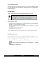
III.2.3 Printer Connection
Data may be printed without PC by connecting a parallel printer to the parallel port (labeled “centronics” on the Rheometer head. Pre-select “printer” as the output device to
print the data during measurement (see Section 6).
- Turn the R/S-CPS+ Rheometer off with the “POWER” switch at the back of the instrument.
- Insert the printer cable into the “CENTRONICS” port at the back side of the instrument.
- Turn the R/S-CPS+ Rheometer on.
Brookfield Engineering Labs., Inc.
Page 10
M01-213-A0706
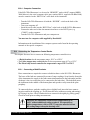
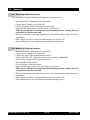
III.2.4 Computer Connection
If the R/S-CPS+ Rheometer is to be used in “REMOTE” mode with PC support (RHEO
2000 Software), the serial computer cable (part number RSS-9, supplied with Rheo2000)
must be connected to the “RS232 Port” at the back of the instrument.
- Turn the R/S-CPS+ Rheometer off with the “POWER” switch at the back of the
instrument.
- Turn your computer off.
- Insert the serial cable into the “RS232 Port” at the back of the R/S-CPS+ Rheometer.
- Connect the other end of the data transmission line to a free RS232 port (e.g.
“COM2”) on the computer.
- Turn the R/S-CPS+ Rheometer and your computer on.
You must use the computer cable supplied by Brookfield!
Information on the installation of the computer system can be found in the operating
manuals of the specific computers.
III.3 Connecting the Temperature Control Device
This chapter discusses how to connect to following temperature control devices:
• A Bath/circulator for the temperature range -20°C to +250°C
• The Peltier temperature control device for the temperature range 0°C to +135°C
• The Electrically heated controller for temperature range of 50°C to 250°C
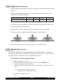
III.3.1 Connecting a Bath/Circulator
Hose connections are required to connect a bath/circulator to the R/S-CPS+ Rheometer.
The hoses of the bath are connected by means of snap couplings. Seen from the front side
of the instrument, the supply is the front connection(connected to the bath outlet) and the
discharge is the rear connection (to be connected to the bath inlet). The bath fluid enters
the instrument in the middle of the bottom plate and spreads evenly towards the plate
periphery.
To connect the hoses, push the coupling sleeve slightly back, insert the hose connecting piece and let the coupling go. It will fasten the hose (without screwing and turning)
by locking it in place. Check whether the hose connection fits tightly by pulling gently.
Check for leaks prior to taking measurements.
The R/S-CPS+ Rheometer can be used at temperatures up to
+90°C without additional cooling required. For operation at
higher temperatures (+90 to +250°C), tap water must be fed into
the cooling flange to keep the bearings cool!
Brookfield Engineering Labs., Inc.
Page 11
M01-213-A0706
The bath liquids normally used are:
-10°C to +90°C
water (de-ionized) - glycol mixture
-20°C to +250°C
Silicone bath oil
Silicone bath fluids can be ordered from BROOKFIELD.
We recommend strongly that the upper temperature limit be set at
the liquid circulating thermostat to +90°C if water is used and to
+250°C if oil is used.
III.3.2 The Peltier Temperature Control Device
If the R/S-CPS+ Rheometer is equipped with a Peltier temperature control device or
electric heater (P1 or P2 or E1) a bath/circulator is not used. The control of a Peltier and
Electric control devices are explained in separate manuals.
Brookfield Engineering Labs., Inc.
Page 12
M01-213-A0706
IV. Environment, Handling, Cleaning and Maintenance
IV.1 Operating Environment
Find a comfortable, convenient working place to install your R/S-CPS+ Rheometer. There
should be enough room to place the Rheometer, the measuring systems, the testing material
and the peripheral devices (e.g. printer, computer and thermostat). You need a grounded outlet
to operate the R/S-CPS+ Rheometer, and you need additional outlets for the connection of each
peripheral device. Your operating environment and the place where you store the R/S-CPS+
Rheometer should not be extremely hot, cold or moist. Locations with strong temperature and
humidity fluctuation should be avoided. Be sure the R/S-CPS+ Rheometer is not exposed to
the following:
• heavy dirt or dust,
• direct sun radiation,
• objects that emit strong heat (e.g. heating radiators),
• objects with a strong electromagnetic field (e.g. loudspeakers, motors etc.),
• liquids or corrosive chemicals.
IV.2 Handling
The R/S-CPS+ Rheometer is designed to work under light bumps or with vibration. You must,
however, avoid dropping it or exposing it to heavy shock!
Never lift your R/S-CPS+ Rheometer by the cone or plate coupling, or
by an attached cone or plate. Avoid anything that might impair the free
and concentric rotation of the measuring element coupling (e.g. shock).
The Rheometer includes electronic torque overload protection and is not damaged if maximum
torque load (50 mNm) is exceeded.
IV.3 Cleaning
The paint coating of the R/S-CPS+ Rheometer resists damage by most solvents and weak
acids. Use a clean, dry, soft and nap-free cloth to clean the housing. Neutral detergents may be
used to clean the housing.
Do not use chemical products such as strong solvents or strong acids to
clean the housing, especially the keyboard.
Make sure NO liquid penetrates into the housing (e.g. through the
instrument connecting sockets) and into the bearings of the drive. This
could destroy the instrument!
Brookfield Engineering Labs., Inc.
Page 13
M01-213-A0706
IV.4 Maintenance
Work on control electronics, all accessories, the measuring drive, the
AC-adaptor and all cables and connections may only be carried out by
authorized service personnel trained by Brookfield Engineering.
Measurement accuracy can be checked by the customer at any time. We recommend this measurement be done with mineral oil standards.
Brookfield Engineering Labs., Inc.
Page 14
M01-213-A0706
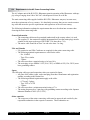
V. Measuring Systems
The following types of geometries are available for use with the R/S-CPS+/P1/P2/E1
Rheometer:
a) cone/plate
b) plate/plate
Select a suitable measuring system in the range required for your measurements (see Appendix
A1).
When cones are used, the shear rate is the same across the entire measuring area. The available
cone angles are α=1° and α=2°. The tip of the measuring cone has been removed to avoid contact and friction with the bottom plate. Each cone is supplied with a data sheet that identifies
the cone truncation in millimeters.
Flat (parallel) plates are typically used when there are particles in the sample. It is possible to
adjust the gap distance between 0.3 ... 3 mm. The shear rate changes with gap used so the gap
must be entered when running a test with P25, P50 or P75 plates.
ANGLE
RADIUS
Figure 4.: Measuring cone for R/S-CPS+ Rheometer
V.1 Inserting and Adjusting the Measuring Elements
The cone/plate and plate/plate measuring systems consist of the fixed bottom plate and the upper measuring cone or flat (parallel) plate. The top element will move up and down using the
height adjusting lever.
The instrument head is lifted to insert the geometry. To do so, move the height adjusting lever
forward to raise the instrument head. Push the coupling sleeve up so the red ring is visible.
Insert the measuring element (cone or plate) in the coupling. Push the sleeve down (red ring
covered) until the measuring element is held tight by the coupling.
Loosen the hexagon socket screw on the measuring system to allow the cone and cone shaft to
move freely.
Brookfield Engineering Labs., Inc.
Page 15
M01-213-A0706
Clockwise to Lower
Counter-clockwise to Raise
Micrometer ring (nonius)
for precise adjustment
Measuring Point (red)
0.01
M
Height Mark
0
Figure 5: Setting the gap on the R/S-CPS+ Rheometer
Set the micrometer ring to ZERO by first turning it left (clock-wise) to at least 100 μm (one
complete revolution) beyond ZERO (scale division 0.01 corresponds to 10 μm), and then counter clock-wise back to 0. This will prevent backlash of threads from influencing the accuracy
of the ZERO setting. The height mark “O” must then be set during an upward (counter clockwise) rotation of the micrometer ring.
Lower the instrument head as far as it will go by pushing the height adjusting lever backward.
This will compress the element. Now set the reading on the Measuring Dial to “0”. Lift the
instrument head and lower it again. The reading on the Measuring Dial should read “0” again.
If it does, tighten the hexagon socket screw which will lock the measuring element in this position. If it does not, begin again following the same procedure.
Raise the instrument head and set the micrometer ring to the appropriate gap setting (turning
the micrometer ring counter clock-wise). The red M on the micrometer ring indicates a 0.05
mm gap setting. ALL cones are supplied with a data sheet that specifies the cone truncation in
millimeters. Set the micrometer ring to the cone truncation value listed on the data sheet. This
sets the gap to account for the tip of the cone being removed. For ANY plate, the gap setting
may be selected freely from 0.3 mm to 3.0 mm. A common gap setting for plate/plate measurements is 1.0 mm, but this is user definable depending on the material being tested and the size
of particles within the sample, if any. The micrometer ring can be locked slightly at the back
by means of a hexagon socket screw M3.
Brookfield Engineering Labs., Inc.
Page 16
M01-213-A0706
The measuring cone/plate may only be adjusted, and the hexagon socket
screw may only be tightened, when the measuring temperature is set
precisely. Otherwise the gap distances may be changed by thermal
elongation, resulting in faulty measurement or in damage to the
measuring system.
V.2 Filling the Measuring Systems, Measuring
The sample material is placed on the bottom plate with the instrument head in the upper position. Air bubbles in the sample will foul test results and should be avoided. To avoid interfering side effects, remove excess sample from around the cone or plate with a spatula, taking
care not to scratch the surface of the bottom plate.
Remove excess sample from cone or plate edge!
Set the bath, peltier or electric heater to the required temperature if measurements are to be
taken under controlled temperature. Do not begin the measurement until the temperature in the
substance is constant (plate temperature may be displayed by selecting Utilities ( Temperature
measurement).
Be sure to hold the measuring system with one hand when you remove the cone or plate.
Dropping the cone or plate onto the sample plate may damage either piece.
Clean the bottom measuring plate and measuring element carefully without using abrasive objects. (i.e., steel wool). Avoid scratches! When the cone or plate is not in use it should be
stored in the cylindrical container.
Brookfield Engineering Labs., Inc.
Page 17
M01-213-A0706
VI.Operation and Menu System
Beginning with firmware Version 4.02, the R/S-CPS+ Rheometer will display in German or
English.
The language is selected via the menu level Configuration→Language (if English is active)
or Konfiguration→Sprache (if German is active). For more details on language selection, see
Chapter 6.7.6.
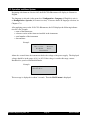
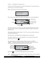
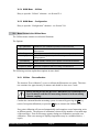
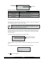
After applying power to the R/S-CPS+ Rheometer, the LCD displays the following information for a few seconds:
• name of the Rheometer
• software version of the firmware installed in the instrument
• serial number of the instrument
• date and time
Example:
R/S-CPS+ Rheometer
Ver.: x.xx
#xxxxxx
07.05.06
15.12
Brookfield
About five seconds later, the instrument checks the voltage of the power supply. The displayed
voltage should be in the range of 14.9 to 16V. If the voltage is outside this range, contact
Brookfield or your local Brookfield Dealer.
Example:
Voltage-Control:
VCC:15.25 V
This message is displayed for about 3 seconds. Then the MAIN menu is displayed.
Brookfield Engineering Labs., Inc.
Page 18
M01-213-A0706
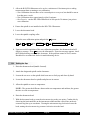
VI.1 Keyboard
MAIN MENU
- Single measurement
- Program measurement
- Remote
>
R/S Plus
RHEOMETER
- Select previous menu entry
- Input: increment numerical
value/letter
ON
- Select next menu entry
- Input: decrement numerical
value/letter
ST
OK
START/STOP
- Back to parent menu
- Abort
- Start of measurement
- Abort measurement
OK
- Accept
- Select
- One digit to the right
- One digit to the left
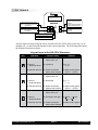
All user inputs are made using the 6 keys located below the LCD. Some of the keys are of
multiple use, i.e. their function depends on the current operation. The following table shows
the keyboard functions in detail.
Keypad layout of the R/S-CPS+ Rheometer
Key
Operation
Function of Key
Example
1) Menu 1) Select menu entry
above active one
1)Utilities → Remote
2) Input of numerical values
2) Increment
2)8 → 9
A→B
3) Selection from list
3) Select list element
above active element
3)Select meas. system
CP50-2 → CP50-1
1) Menu 1) Enable menu entry
below active one
1)Remote Untilities
2) Input of numerical values
2) Decrement
2)5 → 4
F→G
3) Selection from list
3) Select list element
below active element
3)Select meas. system
CP50-1 → CP50-2
1) Menu 1) Select menu entry
above active one
1)Utilities → Remote
2) Input of numerical values
2) One digit to the right
2)100.00 → 100.00
Test → Test
3) Selection from list
3) Select list element
above active element
3)Select meas. system
Brookfield Engineering Labs., Inc.
Page 19
M01-213-A0706
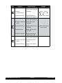
Key
Operation
Function of Key
Example
1) Menu 1)Enable next menu
1) Remote → Utilities
entry below active one
2) Input of numerical values
2)Last digit
2) 100.00 → 100.00
Test → Test
3) Selection from list
3)Select list element
below active element
3) Select meas. system
1) Menu
1)Return to parent menu 1) Utilities → Main
(turn page downward)
2) Input of numerical 2)Abort input (only if
values
possible)
ST
OK
3) Selection from list
3)Abort selection (only if
possible)
4) Measurement
4)Start and abort measurement
5) Remote operation
5)Abort measurement
back to main menu
1) Menu
1)Select active menu
level (open sub-menu)
2) Select meas. system
→ back to menu
2) Input of numerical 2)End of input/accepvalues
tance
3) Selection from list
Brookfield Engineering Labs., Inc.
3)Select active list element
Page 20
M01-213-A0706
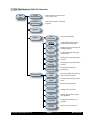
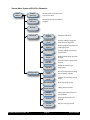
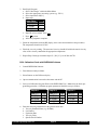
VI.2 Menu System of R/S-CPS+ Rheometer
Main
Menu
Single
Measurement
Measurement at constant shear
rate or shear stress
Program
Measurement
Measurement with user-defined
program
Remote
Utilities
Zero
Calibration
Process
Program
Creation/editing of programs
(ramp functions included)
Print
Programs
Printing program parameters of
existing programs
Measuring
Systems
Creation/editing of measuring
system factors
Print
Memory
Printing of measuring data from
memory
Clear
Memory
Clearing of measured data from
memory
Measure
Temperature
Configuration
Permanent measuring of
temperature
Output
Mode
Pre-select output of measuring
data via printer or RS232
Meas-Count
Mode
Selection of measuring counter
mode
Meascount=0
Reset measuring counter
Time/Date
Setting of time and date
RS232
Parameters
Setting of transmission parameters for RS232
Language
Language selection for user
prompts
Service
Service2
Brookfield Engineering Labs., Inc.
Zero-point calibration
Page 21
Only for service personnel!
M01-213-A0706
Menu Handling
The first menu displayed after turning on the instrument is the main menu. Only part of the
menu (three entries) is displayed at a time because the LCD of the R/S-CPS+ Rheometer cannot show all menu items simultaneously. An arrow “>” on the right side of the display indicates there are more entries in the menu.
The currently active (but not yet selected) entry is marked by a blinking field (cursor) on the
left side of the LCD.
Example:
Active entry: press
OK to select
MAIN-Menu
Run Single
-Run Program
-Remote
>
This menu contains
additional entries
Using the
and
keys, you can move the cursor up and down in the menu until the desired menu entry is reached.
Note: If there are more menu entries in the menu when you have reached the end of the display, the next part of menu will be opened automatically (scrolling).
You can “Start” the menu entry by pressing the OK key, as well as open the related sub-menu.
If you are in a submenu and wish to return to the upper menu, press the ST key.
VI.3 Selecting from Lists
Selection from a Menu List is required for the following:
• Select a measuring system for measurement e.g.in “Single measurement” or “Edit Program”
• Select pre-set values for measurement e.g. in “Single measurement” or “Edit Program”
• Select a program or a measuring system you want to edit in “Edit Program” and “Measuring systems”
• Answer a request “YES” ↔ “NO”.
• Select the program to be started in “Program measurement”
The
and
keys move the cursor up and down the list.
The OK key selects the entry, ST aborts the selection from the list (only if possible).
Brookfield Engineering Labs., Inc.
Page 22
M01-213-A0706
Select Meas.system:
1) CP25-2
2) CP50-1
3) CP50-2
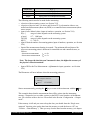
VI. Input of Numerical Values and Alphanumeric Texts
Most user defined entries are numbers. User defined values such as the Start and End values
of a ramp, number of measuring points, factors, time, date etc. are entered as numbers with or
without decimal digits.
If the display shows the decimal point in a number to be entered, input of a floating-point number is requested. However, the number of digits after the decimal point is limited to the number of displayed decimal digits, i.e. the decimal point cannot be moved during input.
The digit to be changed is indicated by a bar under the digit.
The following example indicates the input of numerical values. We will change the value of
shear rate (Val.[1/s]) from 0100.00 to 290.00.
The cursor bar is located under the“1” in the entered shear rate (currently 100.00 s-1).
Input Values:
Val.[1/s]: 0100.00
Nr. of MP: 010
time[s]: 0230
The “1” can be changed (incremented or decremented) by using the
Press the
and
keys.
key once to get:
Input Values:
Val.[1/s]: 0200.00
Nr. of MP: 010
time[s]: 0230
The cursor can be moved right or left by using the
press the
and
keys. To change the next digit,
key:
Input Values:
Val.[1/s]: 0200.00
Nr. of MP: 010
time[s]: 0230
The next digit can now be changed. In order to insert “9” in place of “0”, press the
once:
Brookfield Engineering Labs., Inc.
Page 23
key
M0-23-A0706
A
Input Values:
Val.[1/s]: 0290.00
Nr. of MP: 010
time[s]: 0230
Note: If you press and hold one of the keys
or
while entering numbers, the digit will
first increment or decrement by +/- 1. However, after a short period of time, the process
will continue automatically. This corresponds to the Repeat Function of computer
keyboards.
In this example,
could be pressed and and held until the “9” is displayed. The
repeat function is only active during numerical and alphanumeric input.
When the desired number is displayed, accept it by pressing the OK key. In this example, the
cursor now moves to the first digit of the next field to be entered.
Alphanumeric inputs
Some fields allow for both numbers and letters. These are entered the same way as previously
discussed for numeric fields. The available entries are “0” to “9”, “A” to “Z”, and the blank
symbol “ ”. If you wish to change the letter “B” to the number “7”, press and hold the
or
keys until the “7” appears at the display.
Alphanumeric input is available when assigning a Name to a user defined Program, or an ID to
a user defined Test Measurement.
VI.5 Menu Entries (MAIN menu)
Menu entries (see Section VI.2) either lead to submenus (e.g. “Utilities” or “Configuration”),
or they start one of the Rheometer’s functions directly.
All gray fields in the tree chart in Section VI.2 that have no further right branches start functions. Those with right branches are submenus.
Recall the keyboard layout from Section VI.2. By pressing
and
the cursor (black rect-
angle) moves up and down. The OK starts a function. If a submenu is assigned to the entry it
will open, otherwise the function of the Rheometer is started. The functions of the R/S-CPS+
Rheometer are described in detail in this section.
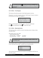
VI.5.1 MAIN menu → Single Measurement
This function measures shear stress or shear rate (CSS or CSR) at constant user defined
values.
The user may select the physical unit from the following:
Brookfield Engineering Labs., Inc.
Page 24
M01-213-A0706
Shear Rate
D [s-1]
Speed
n [U/min] or [rpm]
Shear Stress
Tau [Pa}
Torque
M[‰] [1000 ‰ correspond to 50 mNm]
The following entries need to be made before measuring:
• selection of the measuring system (see Section VI.3)
• selection of physical unit (see above and Section VI.3) to determine either a controlled rate measurement (shear rate, RPM) or a controlled stress measurement (shear
stress, torque).
• input of user defined values (input of numbers, operation, see Section VI.4)
D [s-1]
range of values depends on the measuring system
n [rpm]
0.7... 1,000 rpm
Tau [Pa] range of values depends on the measuring system
M[‰] 0 ... 999 ‰
• input of desired number of measuring points (input of numbers, operation, see Section
VI.4)
• Input of the measurement duration in seconds. The minimum allowed interval between two measuring points is different for controlled rate and controlled stress, as
follows:
- shear rate measurement
tMP >= 4 s
- shear stress measurement tMP >= 1 s
Note: The longer the time between 2 measured values, the higher the accuracy of
the physical values determined!
• Input of ID for the Test Measurement. (alphanumeric input, operation - see Section
VI.4)
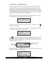
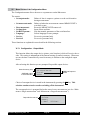
The Rheometer will now indicate where the measuring points are:
Output of MPs to:
- no output-device
- memory
< >menu
<ST>START_
Start a measurement by pressing the ST key or return to the main menu with the
key.
This example shows that the measurement data will be written into the instrument
memory. Output devices are either a printer or the RS232 serial interface of the Rheometer. Pre-selection of these devices is described in the Section “Configuration → Output
mode”.
If the memory is full and you want to keep the data, you should abort the “Single measurement” function, print out the data from the memory or send the data to a PC (see
“Utilities → Print Memory”). Then you may clear the data from the memory (see chapter
Brookfield Engineering Labs., Inc.
Page 25
M01-213-A0706
“Utilities → Clear Memory”) and run your test.
Tests may run with full memory but the results will not be saved. They will be shown on
the LCD as they come from the instrument.
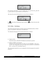
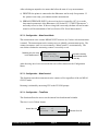
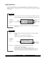
When a measurement is started, the instrument shows:
Program running
Wait for 1.MP
#01
This message will be displayed until the first measuring point is reached and displayed.
Torque
Duration
100.5 ‰ 000.90 1/s
Eta:
1.728Pas
Tau:
1.572Pa
04s
20.7°C
User defined value
Measurement results
#01
Step (in single meas.
always 01)
Temperature
If the torque is below 10 % (scale is 0% to 1,000%), the measurement results are often
inaccurate. In this case the user defined parameters should be changed so the torque is
higher than 10%.
If the display field for the torque indicates: “M→0!”, these values are below the range of
resolution of the Rheometer.
If the temperature is not displayed, the measuring sensor is not connected.
The display is updated every new measuring point. The current measurement can be
aborted at any time with the
key.
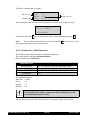
After a measurement or an abort, the display field for Step indicates “END” or
“ABORT”. The display alternates at intervals of about four seconds between the last
displayed measuring point and information about the measurement:
Reason for
abort or end
Duration until
abort or end
Program end
Single measurement
Total time: 100s
Total #MP:
10
Type/name of
executed progr.
Number of measuring
points measured
By pressing OK you stop the alternating display and return to the menu.
Note: The last selected program parameters remain in the memory even after switching
off the Rheometer.
Brookfield Engineering Labs., Inc.
Page 26
M01-213-A0706
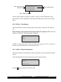
VI.5.2 MAIN menu → Program Measurement
This function begins a user defined measurement program. With a Program Measurement, the user can also set values as a linear function of time, such as D[s-1] = f(t). It
is useful to use a “Program measurement” when doing repeat measurements involving
the same preset values and the same measuring system. The user only needs to run the
Program rather than select parameters each time they need to run the test. Four standard
programs (and more optional ones) may be defined. Section VI.6.2 “Utilities → Edit Program” describes how to prepare or modify such a program.
The function “Program measurement” begins one of the available programs. If there is
no program available, the following error message is displayed:
No valid program
Enter program first!
In such a case you have to define a program first (“Utilities → Edit Program”). Use OK
to return to the main menu.
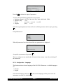
If programs are available, a list appears to select from. Select the program to be started
(selection from the list, operation, see Section VI.3).
Select PROG to run
1) Prog xyz
2) Test
3) Prog oil 2000
If the OK key is used to select the program (in this example, the program named “Test”),
this operation is followed by the option to enter an ID (identification text of the measurement). A name for the measurement may be entered here (maximum 15 characters - for
alphanumeric input, see Section VI.4).
Meas. series
identification
Input measuring-id
Meascount:
125
Id: oil 2000 040596
Automatic increment at
every measurement
When you have entered “Id” the Rheometer will indicate where the measuring points will
be outputted to before a measurement begins.
Output of MPs to:
- Printer
- memory
< >menu
<ST>START_
Brookfield Engineering Labs., Inc.
Page 27
M01-213-A0706
Start a measurement by pressing ST or return back to the main menu with
.
In the above example, the results will be outputted to memory and printed to the printer
connected to the Rheometer. Options for output devices include a printer, the RS232 serial interface or no output device. The section “Configuration → Output mode” describes
this in detail.
If the memory is full, you should consider aborting the “Program measurement” function,
printing the data from the memory or sending it to a PC (see chapter “Utilities → Print
memory”) and then clearing the data from the memory (see chapter “Utilities → Clear
memory”).
Measurements can be taken with the memory full but the results will only be shown at the
LCD and will be lost after completion of the measurement. If you try to send results to
a printer and it is not connected or has no paper in it, an error message will be displayed
until the printer is connected and operational or until you abort the activity.
When you start the measurement the instrument shows:
Program running...
Wait for 1.MP
#01
This message will be displayed until the first measuring point is displayed.
Torque
Duration
100.5 ‰ 000.90 1/s
Eta:
1.728Pas
Tau:
1.572Pa
04s
20.7°C
Actual pre-set value
Measurement result
#01
Current step
Temperature
If the torque is less than 10 ‰ the results may be out of instrument range. The user
should consider changing the user defined values to get a torque higher than 10 ‰.
If the display field for the torque indicates: “M→0!”, these values are below the range of
resolution of the Rheometer.
If the temperature is not to displayed, the measuring sensor is not connected and the
printout of the temperature will be printed as 1000.0 °C!
The display is updated at every new measuring point. The current measurement can be
aborted at any time with the ST key.
Brookfield Engineering Labs., Inc.
Page 28
M01-213-A0706
After measurement, or after an abort, the display field for step indicates “END” or
“ABORT”. The LCD alternates at intervals of about four seconds between the last displayed measuring point and information on the measurement:
Reason for
abort or end
Duration until
abort or end
Program end
Single measurement
Total time: 200s
Total #MP:
40
Type/name of
executed progr.
Number of measuring
points measured
Pressing OK ends the alternating display and returns to the main menu.
VI.5.3 MAIN menu → Remote
The “Remote” function initiates measurements to be made under PC control. In this
mode all functions of the R/S-CPS+ Rheometer are controlled by a PC. For PC-controlled measurement you need the software package RHEO 2000. This software operates
under the Microsoft™ Windows 3.1, Windows for Workgroups 3.11, Windows 95, 98 and
NT. More detailed information on RHEO 2000 can be obtained from your supplier.
After selection of the “Remote” option, the Rheometer displays the following:
Remote
Wait for RS232...
The Rheometer waits for communication with a PC. Data transfer between the PC and
the Rheometer is performed through the RS232 serial interface of the R/S-CPS+ Rheometer.
If RHEO 2000 is installed on the PC, the REMOTE (MEASURE) program can be run
and this operation can be ended at any time by the ST key. The current measurement is
also aborted by pressing the ST key in REMOTE operation.
On completion of the communication with the PC, the LCD shows: “Remote done ...”
Pressing the key ST will return the display to the Main Menu.
During measurement in REMOTE operation, the LCD will display various information
which is used to provide troubleshooting information in case errors occur. This information should be disregarded.
Brookfield Engineering Labs., Inc.
Page 29
M01-213-A0706
VI.5.4 MAIN Menu → Utilities
Entry to open the “Utilities” submenu - see Section VI.6.
VI.5.5 MAIN Menu → Configuration
Entry to open the “Configuration” submenu - see Section VI.6.
VI.6 Menu Entries in the Utilities Menu
The Utilities menu contains several useful functions.
The Options:
Zero Calibration
Initiates the zero calibration procedure of the rheometer
Edit Programs
Input or modification of programs which are started with Program
Measurement
Print Programs
Prints all parameters of all the programs in memory to the printer
Measuring Systems
Input of measuring system parameters or generation of new measuring systems
Print Memory
Delete Memory
Temperature Meas.
Output of data in memory to the printer or to the serial interface
Clears all data from memory
Measures temperature without running a measurement
The following sections explain these options in more detail.
VI.6.1 Utilities → Zero calibration
The function “Zero calibration” serves to calibrate the Rheometer zero point. This function continues for approximately 10 minutes and should be done once a week.
Before starting be sure the R/S-CPS+ Rheometer has warmed up for at
least 10 minutes, and that NO measuring element is in the measuring
element coupling.
Confirm the command that the measuring system is removed by pressing the OK key
(start of zero point calibration), or press the ST key to return to the Utilities menu.
Zero point calibration will proceed automatically and comprises several measuring series
at different speeds. The progress of calibration is shown by the number of executed steps
of the total steps. If an error message appears during zero calibration, repeat the zero
calibration. If the error message is displayed again there may be a technical defect (→
repair).
Brookfield Engineering Labs., Inc.
Page 30
M01-213-A0706
After successful calibration, the values of the zero point are stored internally. These values are preserved until the next calibration.
Press any key to return to the Utilities menu.
Note: You can abort zero point calibration at any time with the ST key. The zero point
values determined up to that point will be ignored.
VI.6.2 Utilities → Edit Program
This function allows the input of new, and the modification of existing programs. The
programs may be run after successful creation via the menu level “Program measurement” in the main menu.
The following values are user definable in a program:
• measuring system to be used
• preset value for measurement, e.g. shear rate D[s-1]=f(t), as a function of time
• number of measuring points in the program
• duration of measurement
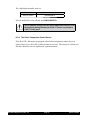
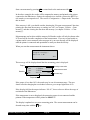
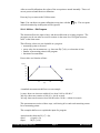
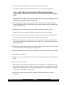
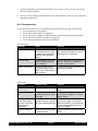
Preset value as a function of time:
D[1/s]
100
80
D[1/s]=f(t)
60
40
20
0
0
60
t[s]
120
180
A standard measurement shall serve as an example.
1st step: shear rate increases within 60 sec from 10.00 to 100.00 s-1.
2nd step: shear rate remains at 100. 00 s-1 for 60 seconds
3rd step: shear rate decreases from 100.00 back to 10.00 s-1 within 60 seconds
This measurement consists of three steps, each lasting 60 seconds and containing a number of measuring points.
This example shall serve to explain the input of a program.
Apart from the shear rate D [s-1] = f(t),
speed
n [rpm] = f(t)
torque
M [‰] = f(t)
Brookfield Engineering Labs., Inc.
Page 31
M01-213-A0706
shear stress Tau [Pa] = f(t)
can be used as preset values within a defined program. The ramps and straight lines of
the preset values are linear (i.e., if the ramp time is 60 seconds and four readings are
taken, the readings are taken at 15 second intervals).
The assignment of user defined values to be processed in each measuring point is calculated with the following formula:
Δ Preset Value = End Value - Start Value/(Number of Measuring points - 1)
The first user defined value (=the first measuring point) is always the start value of the
ramp. The last measuring point is determined as the end value of the user defined value
range. As in our example, to reach the values D= 10, 20, 30, ... , 100 [s-1] a starting value
of 10 [s-1] is used with increments of 10, therefore 10 measuring points is required. To
check: 100-10/(10-1)=10.
Back to the example.
After selection of the menu level “Edit Program” the user will be prompted to select the
program.
Available programs
contain a name
Select PROG to edit
1) Prog xyz
2) Test
3) NEW
All free (non-defined)
programs are marked NEW
All free programs are initially marked as NEW. To avoid overwriting existing programs,
select NEW as a program to be edited and select a measuring system.
Attention: Any defined program MUST ALWAYS be executed with the same measuring
system, otherwise improper results will be calculated.
Select Meas. system:
1) CP25-1
2) CP25-2
3) CP50-1
>
>
The measurement type is selected:
Select Input-Mode:
-D[1/s]
-n[rpm]
-Tau[Pa]
Brookfield Engineering Labs., Inc.
Page 32
>
M01-213-A0706
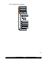
Available Measurement Types User Defined Range
Shear Rate D{s-1]
Depends on the measuring system
Speed n[rpm]
0.7 - 800 rpm
Shear Stress Tau [Pa]
Torque M[‰]
Depends on the measuring system
Output of data in memory to the printer or to the serial
interface
Select the type of measurement and press the OK key (in our example “D[1/s]”). Now
enter the user defined values for each step one after the other.
Enter the number of steps (the number of ramp and straight line functions).
Nr of steps: 03
Input number of
steps 1 - 10. This
example is 03.
The number of steps can range from 1 to a maximum of 10 steps. In this example, we
need three steps, so the number “01” is changed to “03” - (seeinput of numbers - Section
VI.4). The message “Range error” will appear if <1 or >10 is entered.
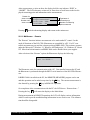
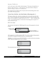
The following inputs have to be made for each step:
End Value
Input Step Nr. 1
Start[1/s]:0100.00
End[1/s]: 0100.00
Nr. of MP: 001
Start Value
Number of MP (data points)
(Input of numbers: see Section VI.4)
Minimum and maximum Start and End values depend on the selected measuring system
for shear rate (D[s-1]) and shear stress (Tau [Pa]). At input, the Rheometer checks the
Start and End values and indicates the message “Range error” if out of range:
Allowed minimum value
Range error
Start value:
Min:
0.00
Max:
2400.00
Name of value out of
range
Allowed maximum
value
For example, this message would be displayed if a start value for D[s-1] is not within the
range of 0 - 2400.00 s-1 when using measuring cone CP50-2.
If the Start value, End value and number of Measuring Points are acceptable, the user will
be prompted for Step Duration:
Brookfield Engineering Labs., Inc.
Page 33
M01-213-A0706
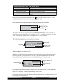
Number of steps
being edited
Input Step Nr.
time[s]: 0004
1
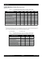
Step duration
Minimum step duration:
Available Measurement Types User Defined Range
Shear Rate D{s-1]
tmin = number of measuring points * 4 s
Speed n[rpm]
Shear Stress Tau [Pa]
tmin = number of measuring points * 4 s
tmin = number of measuring points * 1 s
Torque M[‰]
tmin = number of measuring points * 1 s
Maximum step duration: 3600 s
The instrument will automatically check the input. If there is a range error, “Range error”
will be displayed together with the allowable range.
The more time between two measuring points, the higher the accuracy
of the determined physical parameters!
The input procedure for Start and End value, number of Measurement Points and Step
Duration is repeated for the next step (step 2). The procedure is repeated until all steps
have been entered.
The program will then prompt the user for a program name.
Edit PROGRAM-Name
NEW
Enter the name under which
the program is to be stored
For this example, we will use “TEST”. (For the input of alphanumeric texts see Section
VI.4)
The instrument will prompt the user to store the Program with the Name:
(2)
TEST
<OK>=save_
Press OK to store the program.
Brookfield Engineering Labs., Inc.
Page 34
M01-213-A0706
If any other key besides OK is pressed, the entries are abandoned and
those parameters of the program position existed before editing will be
preserved.
VI.6.3 Utilities → Print Programs
This function will print the parameters of the defined programs in memory.
If the printer is not ready for operation when the “Print Programs” function is initiated,
the following error message will be displayed:
ERROR # 1
Printer not ready!
<OK>cont.
<ST>stop
If this error message appears, ensure the printer is ready and contains paper.
Press OK to try printing again or press ST to return to the menu.
VI.6.4 Utilities → Measuring Systems
This function provides a method to create new measuring systems or change existing
measuring systems.
The following values can be edited:
• name of measuring system
• shear rate factor
K( [min/s]
• shear stress factor (‰ [Pa]
(k_gamma)
(tau_prom)
Only authorized personnel are permitted to change constants of the
measuring system!
After starting the function, you will be prompted to select the measuring system you want
to edit. Select the list item “NEW” to generate a new measuring system.
Select Meas. system:
1) CP25-1
2) CP25-2
3) CP50-1
>
>
After selection of the measuring system entry the user is prompted to enter Name, tau_
prom and k_gamma.
Brookfield Engineering Labs., Inc.
Page 35
M01-213-A0706
Enter Meas. syst. #4
Name: CP50-1
tau_prom: 01.1418
k_gamma:
01.2910
The measuring system Name is entered in alphanumeric form, the factors tau_ prom and
k_gamma entered as numerical entries (see Section VI.4).
After entry, the system will prompt the user to store the new parameters.
<OK>=storing
Name: CP50-1
tau_prom: 01.1418
k_gamma:
01.2910
Use OK to store the new information, otherwise press the ST to return to the menu without storing.
VI.6.5 Utilities → Print Memory
This function allows the output of the data stored in the instrument memory to either a
printer or to the RS232 serial interface of the Rheometer.
The instrument will prompt you to select the output device, as follows:
Sel. output-device:
-Printer
-RS232
a) Output to printer:
The printer must be connected to the Rheometer and ready for operation.
b) Output to the RS232 serial interface:
The data receiving side (typically a PC) must be set to No Handshake. If the receiving side is not set up properly, the data will either not be transmitted or transmitted to
Null. (see Section VI.8 “Serial Data Transfer”).
After choosing the output device you are prompted to select the program to be printed or
transferred.
Brookfield Engineering Labs., Inc.
Page 36
M01-213-A0706
Meas. Series Counter
MEASCOUNT
Select Program:
-1)17.10;11:20
-2)17.10;12:30
-3)17.10;13:40
Time of Measurement
Date of Measurement
The data of the program will print as a table to a printer or will be transferred via the
serial interface. After completion of data transfer, the Rheometer returns to the Utilities
Menu.
VI.6.6 Utilities →Clear Memory
This function deletes all measured data stored in the memory of the R/S-CPS+ Rheometer.
Before deleting, ensure that the data has been archived to a printer or PC. Before the
memory is cleared, the following prompt is displayed:
Clear Memory?
-NO
-YES
If “YES” is selected, the results will be cleared from the memory; if “NO” is selected, no
deletions are made and the user is returned to the menu.
VI.6.7 Utilities →Measure Temperature
This function displays the temperature with the temperature sensor connected to the Rheometer.
After initiating this function the temperature is measured permanently:
Temperature:
20.5°C
<OK>=return
Push the OK key to return to the Utilities menu.
Brookfield Engineering Labs., Inc.
Page 37
M01-213-A0706
VI.7 Menu Entries of the Configuration Menu
The Configuration menu allows the user to set parameters on the Rheometer.
The entries:
• Set output-mode:
Defines if data is output to a printer or to the serial interface
during measurement.
• Set meascount mode: Defines whether the measurement counter MEASCOUNT is
reset daily or not.
Resets the MEASCOUNTcounter to 0.
• Reset meascount:
• Set time/date: Input of date and time.
• Set RS232 param.:
Sets data transfer parameters of the serial interface.
• Language: Selects language for user prompts.
• Service:
For service personnel only
• Service2:
For service personnel only
These functions are explained in more detail in the following sections.
VI.7.1 Configuration →Output Mode
This function defines the output device (printer, serial interface) which will receive the results. This setting is independent of the internal storing of results in memory. When tests
are run, the data is automatically stored in memory in addition to the configured output
device.
After selecting this function you are prompted for possible output devices:
Internal memory only
Additional output
to serial interface
Select output-device:
-No output-device
-Printer
-RS232
Additional output to
printer
Choice of an output device is stored in the instrument by pressing the OK key. This
selection remains stored even after switching off the instrument!
The set output device is prompted before the start of every measurement (see also “Main
menu-> Single measurement” and “Main menu-> Program measurement”).
Output device now set
Brookfield Engineering Labs., Inc.
Output of meas. val. to
-Printer
-Memory
<^>Menu
<ST>Start
Page 38
M01-213-A0706
After selecting an output device ensure that before the start of every measurement:
a) PRINTER: the printer is connected to the Rheometer and is ready for operation. If
the printer is not ready, you cannnot start the measurement.
b) SERIAL INTERFACE (RS232): the receiving device (normally a PC) is set to the
data transfer parameters of the Rheometer (see Section VI.7.5 “RS232 Parameters”)
and ready to receive data. If the receiving side is not ready, the data will not be transmitted or will be transmitted to Null (see Section VI.8 “Serial data transfer”).
VI.7.2 Configuration →MeasCount Mode
The measurement series counter MEASCOUNT increases by 1 before each measurement
is started. The measurement series counter serves to identify a measurement series. The
counter increments until it is reset manually (“MeasCount=0”) or automatically. The
user defines whether the measuring counter is reset daily or not.
Resetting only via menu
level “Meascount=0”
Select meascount mode:
-No resetting
-Reset every day
Automatic resetting
at first measurement
of the day
After choosing one of two reset modes the user will be returned to the Configuration
Menu.
VI.7.3 Configuration →MeasCount=0
This function resets the measurement series counter to Zero regardless of the set MEASCOUNT mode.
Resetting is initiated by answering YES to the YES/NO prompt.
VI.7.4 Configuration →Time/Date
This function allows the user to set the internal clock and internal calendar.
The time is set in 24 hour format.
Hours 00 to 23
Brookfield Engineering Labs., Inc.
Input time
Hour:
17
Minutes:
15
Page 39
Minutes 00 to 59
M01-213-A0706
The date is set as dd.mm.yy format:
Day 01 to 31
Year 00 to 99
Input Date
Day:
17
Month:
15
Year:
01
Month 01 to 12
After setting time and date you will be prompted to store the clock to the new time.
Time/Date
17:15
17:03.01
<OK>=storing
Set the time using the OK key, or return to the menu without storing by pressing ST .
Note:
The new time is entered into the clock only after the OK key is pressed. Note
that storing of the time sets the seconds to 00.
VI.7.5 Configuration →RS232 Parameters
This function allows the preselection of interface parameters.
The serial interface operates without handshake.
Data is transferred as ASCII text.
Parameters to Set
Baud rate [Baud]
Parity
110, 150, 300, 600, 1200, 2400, 4800, 9600, 19200
n(= no parity) e(=even) o(=odd)
Stopbits [Bit]
1 or 2
Databits [Bit]
7 or 8
The standard setting is:
Baud rate = 4800
Parity
= n
Stopbit
= 1
Databits = 8
If you change these settings, you must set the receiving device to the
new transfer parameters as well!
After starting the function “RS232 Parameters” the current settings will be shown:
Brookfield Engineering Labs., Inc.
Page 40
M01-213-A0706
RS232:
4800,8,n,1
Change RS232-Par.?
<OK>YES
<ST>NO
Press the OK to initiate the input of parameters.
You may enter the following parameters in succession:
• Baud rate [Baud]: 110, 150, 300, 600, 1200, 2400, 4800, 9600, 19200
• Databits [Bit]:
7 or 8
• Parity:
n (=none) e(=even) o (=odd)
• Stopbits
[Bit]:
1 or 2
Select the required parameter from the list of available parameters and accept by pressing
OK .
Example Baud rate:
Baud rate:
-4800
-9600
-19200
When all parameters have been selected the new parameters are displayed:
RS232:
19200,8,n,1
<OK>=storing
Accept the set parameters by pressing OK .
The new settings are now stored and will remain in the memory even after switching off
the instrument.
VI.7.6 Configuration →Language
This function selects the user language of the R/S-CPS+ Rheometer. Available languages
are:
• German
• English
Select desired language and press OK . The selected language will be preserved in the
instrument even after it is switched off.
Brookfield Engineering Labs., Inc.
Page 41
M01-213-A0706
VI.7.7 Configuration →Service
These functions are for service personnel only. Password-protected!
VI.8 Serial Data Transfer via the RS232 Interface
Serial data transfer should only be done when the user of the Rheometer has basic knowledge
of data processing and is capable of changing data transfer parameters on the sending and
receiving sides.
Data can only be transferred successfully when transmitter (=R/S-CPS+ Rheometer) and receiver (e.g. a PC) fulfill the following requirements:
1. The instruments are properly connected by the interface cable which is delivered with the
instrument. Caution: Both instruments must be switched off while the connection is
made! (Pin assignment: see Appendix to this documentation).
2. The transmitter (R/S-CPS+ Rheometer) and the receiver are set to identical data transfer
parameters (for R/S-CPS+ Rheometer, see Section VI.7.5. “RS232 Parameters”).
3. The receiver has enough computing and memory capacity to receive or store the data.
The following example demonstrates reception by means of the terminal program under Microsoft™ Windows.
1. Switch the Rheometer and the PC off.
2. Connect the Rheometer (connector RS232 at the back side of the instrument) with a free
serial interface (e.g. COM2) of the PC. Use the cable supplied by Brookfield.
3. Switch the PC and the Rheometer on.
4. Set the data transfer parameters at the Rheometer (see Section VI.7.5). Here: Standard
setting 4800 Baud, Parity n, Stopbit 1, Databit 8.
5. Select the RS232 interface as the output device at the Rheometer (see Section VI.7.1).
6. Open the “Windows Accessories” program group on the PC.
7. Start the “Terminal” program.
8. Select the menu level “Settings” →“Data transfer.”
9. First, a window will appear where you can set the data transfer parameters:
- Select from “Connection” the COM-port to which the Rheometer is connected.
- Set “Baud rate” to “4800”.
- Set “Databits” to “8”.
Brookfield Engineering Labs., Inc.
Page 42
M01-213-A0706
-
-
-
-
-
Set “Stopbits” to “1”.
Set “Parity” to “No parity”.
Set “Protocol” to “No protocol”.
Deactivate “Parity check” checkbox (if crossed).
Deactivate “Carrier signal detection” checkbox (if crossed).
- Finish input by pressing OK .
10.Select the menu option “Settings” → “Terminal Settings”
A window will appear where the user can set the terminal functions:
- Select “English” option.
- Activate “IBM in ANSI” (if not crossed yet).
11.Parameters of the terminal program that have been changed up to this time can be stored
under the menu option “File” → “Store” by entering the file name, e.g. “R/S-CPS+ Rheometer.TRM”.
(When the terminal program is started again, this file with can be opened by: “File” →
“Open” and load the parameters for data transfer with the R/S-CPS+ Rheometer.
12.Now select the menu level “Transfer” → “Text file reception”.
- Enter the file name under of the stored data sent from the Rheometer
(e.g. “TEST.TXT”).
- The message “Receiving: TEST.TXT” will then appear in the status line of the
terminal program.
13.The terminal program is now ready to receive data (for more detailed instructions or
troubleshooting on the terminal program, please read your documentation).
14.Start measurement with the Rheometer. Measuring points should appear as text on the PC
display after a short period of time.
15.When the data of one or several measurements have been transferred into the selected
text file, terminate the data transfer and end the terminal program.
Should a receiver other than a PC be used for serial data transfer, the pin assignment of this receiver must be checked before the connection is made. You can find the pin assignment of the
serial interface plug as well as of the data link cable in the Appendix to this documentation.
VII.
Brookfield Engineering Labs., Inc.
Page 43
M01-213-A0706
VII. Measuring
VII.1 Measuring in Manual Operation
You can measure in manual mode by following these brief instructions:
• Install the R/S-CPS+ Rheometer (see Section III).
• Connect the AC adapter (see Section III).
• Connect the printer, which is optional (see Section III).
• Attach the Measuring System, load the sample (see Section V).
Make sure no substance or solvent enters the measuring element coupling, the measuring drive or the electronic unit.
• If doing a temperature-controlled measurement, wait until the sample reaches the desired
temperature.
• Start a Single Point Test or a Program Measurement (see Section VI).
• After running the test, clean the sample area and Measuring System.
VII.2 Measuring in Remote Operation
• Install the R/S-CPS+ Rheometer (see Section III).
• Connect the AC adaptor (see Section III).
• Connect the proper cable to the Rheometer and PC.
• Switch on the R/S-CPS+ Rheometer and select the menu level “Remote”.
• Switch on the computer and all peripheral devices.
• Start the RHEO 2000 software.
• Load a Program within the software
• Attach the Measuring System, load the sample (see Section V).
Make sure no substance or solvent enters the measuring element coupling, the measuring drive or the electronic unit.
• If doing a temperature-controlled measurement, wait until the sample reaches the desired
temperature.
• Start a Single Point Test or a Program Measurement (see Section VI).
• After running the test, clean the sample area and Measuring System.
Brookfield Engineering Labs., Inc.
Page 44
M01-213-A0706
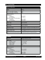
VIII. Technical Data
R/S-CPS+ Rheometer
Dimensions
Weight
Nominal operating voltage
Power consumption (average)
Power consumption (maximum)
Ambient Conditions
Temperature
in operation
out of operation
Relative humidity (not condensable)
in operation
out of operation
Accuracy
Torque range
Torque resolution
Speed range
Angle resolution
Temperature range
Range of shear rate
Range of shear stress
Viscosity range
The given range is a standard value (not maximum
value)
AC Adapter
Dimensions
Weight
Power supply
Operating voltage
Output voltage
Output current
Output power
Frequency
Ambient Conditions
Temperature
in operation
out of operation
Relative humidity (not condensable)
in operation
out of operation
Brookfield Engineering Labs., Inc.
480 mm x 300 mm x 290 mm
12 kg
± 15V, 5V
22W
22W
10° to 40°C
10° to 45°C
20% to 80%
10% to 90%
± 5.0% of stated value
0.05 to 50 mNm
0.01 mNm
0.01 to 1,000 min-1
15.7µrad
-20° to +250°C depending on the thermostatting device used
0 to 6,000 s-1 depending on the thermostatting device used
0 to 16,000 Pa depending on the thermostatting device used
0 to 10,000 Pa•s depending on the thermostatting device used.
Practical low limit is .050 Pa•s for cone/plate measurement.
160 mm x 85 mm x 35 mm
0.5 kg
100 to 240 VAC
5V, ± 15V DC
2A, 0.9 / -0.2A
20W
50 to 60 Hz
+10° to +40°C
+10° to +45°C
20% to 80%
10% to 90%
Page 45
M01-213-A0706
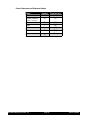
Preset, Measured and Evaluated Values
Value
Speed
Torque (relative)
Symbol
n
M
Physical Unit
[min-1]
[1}
T
t
[°C]
[s]
[s-1]
(1000 ‰ = 50 mNm)
Temperature
Time
Shear rate
γ⋅
Shear stress
τ
[Pa]
Dynamic viscosity
h
[Pas]
Brookfield Engineering Labs., Inc.
Page 46
M01-213-A0706
IX.Guarantee
Brookfield Engineering Laboratories guarantees the faultless functioning of this instrument insofar as it is used and maintained appropriately and connected and handled in accordance with
this Operating Manual.
The guarantee period shall be 1 year from the date of delivery.
The place of guarantee fulfillment is Brookfield Engineering in Middleboro, MA (USA).
All claims of the customer concerning guarantee and damages shall be forfeited if he has
handled the supplied goods improperly, worked on them, or given them to a third party for
reworking without our prior approval.
The total liability of Brookfield Engineering Laboratories and your exclusive claim shall be
limited, at Brookfield´s choice, to either
(a) the refund of the price paid
or
(b) the repair or replacement of the instrument which does not meet the requirements of the
limited guarantee of Brookfield Engineering Laboratories and has been returned with a copy of
your receipt to Brookfield Engineering Laboratories. This limited guarantee shall not apply if
the instrument’s failure is a result of accident, misuse or incorrect application. For a replacement delivery Brookfield Engineering Laboratories guarantees only for the rest of the original
guarantee period or for 30 days, whichever is longer.
Brookfield Engineering Laboratories precludes any further guarantee for the instrument and
related manuals and written materials.
Neither Brookfield nor the suppliers of Brookfield shall be liable for any damages (lost profit,
business interruption, loss of business information or of data or any other financial losses
included) that arise due to usage of this Brookfield product or due to the inability to use this
Brookfield product, even if Brookfield was informed of the possibility of such damage occuring.
In any case, the liability of Brookfield Engineering Laboratories shall be limited to the amount
paid for this product. This exception shall not apply to damages which were caused by intention or gross negligence on the side of Brookfield. Nor shall claims be affected that are based
on mandatory laws concerning product liability.
Furthermore the guarantee conditions of “General Delivery Conditions for Products and Services of the Electric Industry” are valid.
Brookfield Engineering Labs., Inc.
Page 47
M01-213-A0706
Appendix A
A.1 Data Sheets of Standard Measuring Systems
Table A-1: Cone/Plate Measuring Systems according to DIN 53018
(consisting of measuring cone and the bottom measuring plate of the instrument)
Measuring System
C25-1
C25-2
C50-1
C50-2
C75-1
C75-2
Shear rate range [s ]
0-6,000
0-3,000
0-6,000
0-3,000
0-6,000
0-3,000
Shear stress range [Pa]
0-12,223
0-12,223
0-1,528
0-1,528
0-452
0-452
-1
Viscosity range [Pa•s]
0.25-1,629 0.5-3,259 0.03-203 0.06-407 0.009-60 0.02-120
Filling volume [ml]
0.08
0.3
0.7
1.5
2.0
3.9
⋅ [min/s]
Shear rate factor Kγ
6.00
3.00
6.00
3.00
6.00
3.00
Shear stress factor τ‰ [Pa]
12.223
12.223
1.528
1.528
0.4527
0.4527
12.5
12.5
25
25
37.5
37.5
Angle of measuring cone α [°]
1
2
1
2
1
2
Cone truncation [μm]
50
50
50
50
50
50
Radius of measuring cone R [mm]
The data in the following table is for plate/plate systems and is valid for a measuring gap of 1
mm. For other plate distances, please calculate Kγ⋅ with the formula:
Kγ = (2π/60) * (R/H)
R = radius, H = gap
Table A-2: Plate/Plate Measuring Systems according to DIN 53-018
(consisting of measuring plate and the bottom measuring plate of the instrument)
Measuring System
P25
P50
P75
Shear rate range [s-1]
0-1,308
0-2,600
0-3,925
Shear stress range [Pa]
0-16,298
0-2,037
0-603
1.56-9,960
0.097-623
0.02-122
0.5
2.0
4.5
⋅ [min/s]
Shear rate factor Kγ
1.309
2.6175
3.927
Shear stress factor τ‰ [Pa]
16.2975
2.037
0.6036
12.5
25
37.5
Viscosity range [Pa•s]
Filling volume [ml]
Radius of measuring plate R [mm]
Brookfield Engineering Labs., Inc.
Page 48
M01-213-A0706
A.2 Error Messages
The R/S-CPS+ Rheometer is user-friendly regarding errors. When errors occur, they are
trapped, and the user is informed on the LCD. The most frequent error messages are explained
in this chapter.
Range Error
Cause:
User’s error at input. The user has tried to input a value that is less than
the allowed minimum value or is more than the allowed maximum value.
Example of
Faulty Input
Allowed
of a Preset
minimum value
Value:
Range error
End value:
Min:
0.90
Max:
1032.80
Name of value out
of range
Allowed maximum
value
What to Do: Enter the value again. Be sure that the new value is within the allowed
value range.
Printer Error
Cause:
The printer has been selected as the output device but is not ready for
printing.
a] printer cable is not connected to the rheometer
b] paper is out, printer is not on line, other printer errors
Example of
Print Error
Message
Error #1
Printer not ready!
Try again
<OK> cont.
<ST> stop
Abort activity;
do not try again
What to Do: a] make sure printer cable is connected to the rheometer
b] make sure paper try has paper
c] check that the “ready” LED lights of the printer are on
d] remove the error cause at the printer and press OK at the rheometer
e] press ST to abort the process if you cannot find the error cause.
Brookfield Engineering Labs., Inc.
Page 49
M01-213-A0706
Zero Calibration Error
Cause:
Example
Message
An impermissibly high value was measured during the zero point calibration of the rheometer
Error #3
Zero cal. error!
Please retry cal.
<OK> cont.
<ST> stop
What to Do: a] press ST
b] ensure the measuring system has been removed from the rheometer
c] retry zero point calibration - if error occurs again, this is an indication
of a fault in the measuring instrument
Abort: MOMMAX
Cause:
Example
Message
The maximum torque has been exceeded during a measurement
a] utilization of the measuring range is inappropriate for the measured
medium
b]rotation element choked in the measuring cup
ABORT:torque max!
Single measurement
total time:
60 s
total no. of MP: 10
What to Do: a] press OK
b]check whether the measuring system has been fastened properly at the
rheometer
c] if fastened properly, select smaller shear rates or speeds for this measurement or use a measuring system with a higher shear stress factor
Brookfield Engineering Labs., Inc.
Page 50
M01-213-A0706
Abort: Speed Max
Cause:
Example
Message
The maximum speed has been exceeded during a measurement
a] the selected shear stress or torque value for this measurement is too
high
b]a torque or shear stress measurement has been started without substance in the measuring cup
ABORT:speed max!
Single measurement
total time:
60 s
total no. of MP: 10
What to Do: a] press OK
b]select smaller shear stress or torque for this measurement
A.3 Pin Assignment of the Serial Data Cable
The R/S-CPS+ Rheometer is equipped with a serial interface with a 25-pin sub-D-connector
(male) at the back side of the instrument. The serial interface is marked as RS232.
Rheometer
The signal levels are in the range of +12 V
and -12 V in accordance with RS232.
1
13
25
14
Pin assignment of the serial data cable for
serial data transfer to a PC:
Unmarked pins must not be connected!
7
GND
3
RXD
2
TXD
Rheometer side:
25-pin Sub-D-connector (female)
View on soldered connections
All other pins must not be connected!
PC side:
9 pin, sub-D-connector (female)
View on soldered connection
PC
9
5
Brookfield Engineering Labs., Inc.
Page 51
6
1
M01-213-A0706
A.4 Requirements to the AC Power Connecting Cables
The AC adapter unit of the R/S-CPS+ Rheometer permits operation of the Rheometer with supply voltages ranging from 100 to 240 VAC with frequencies from 50 to 60 Hz.
The main connecting cable supplied with the R/S-CPS+ Rheometer may not, in some cases,
meet the requirements of every country. It is absolutely necessary that you use a main connecting cable that meets the specific requirements and regulations of the relevant country.
The following information explains the requirements that are to be taken into account when
choosing the main connecting cable.
General information
• The connecting cable must be permitted (authorized) in the country where it is used.
• The coupler (i.e. the connection with the instrument itself, not the mains plug) must be
suitable for the input socket type CEE22/IEC 320 (data sheet C14).
• The mains cable should be at least 2 m and at the most 3 m long.
USA and Canada
• UL-permission and CSA Certificate are required for the mains connecting cable.
• The following minimal requirements are valid for the cable:
-No. 18 AWG
-Type SV or similar
-3-phase
• The cable must have a nominal rating of at least 10 A.
• The main plug of type NEMA 5-15P (15A, 125V) or NEMA 6-15P (15A, 250V) must
have grounding contact.
Japan
The following cable types and connection values are required in Japan:
• All parts of the cables (cable, socket and plug) must have brand name and registration
number according to the Dentori law.
• The following minimal requirements apply to the cable:
-0.75 mm2, 2-phase
-Type VCT or VCTF
-3-phase
• The cable must have a minimum nominal rating of 7 A.
• The mains plug must be a 2-pin plug with grounding contact according to the Japanese
Industrial Standard C8303 (15A, 125V).
Other countries
• The connectors of the mains connecting cable must be approved and certified by the
responsible authorities in the respective countries. These authorities are:
Brookfield Engineering Labs., Inc.
Page 52
M01-213-A0706
Australia — EANSW
Great Britain — BSI
Austria — OVE
Italy — IMQ
Belgium — CEBEC
Netherlands — KEMA
Denmark — DEMKO
Norway — NEMKO
Finland — SETI
Sweden — SEMKO
France — UTE
Switzerland — SEV
Germany — VDE
- The cable must be three-phase HAR-cable, type HO5VV-F3, with a minimal phase
cross-section of 1.0 mm2. The main connecting cable must be permitted for a rating of at least 10 A and, depending on country, a nominal voltage of 125 V or 250
V AC.
A.5 Language Cross Reference
English
!M (0!
ABORT
Abort:speed max!
Abort:torque max!
Change RS232 Param.?
Clear memory?
Continue
Enter Meas.sys.
Enter program first!
Enter PROGRAM name
End value:
ERROR
Input measuring id
Input step No.
Input values:
Meascount
Meascount mode
Measuring systems
Memory cleared!
Memory
No free memory!
No output device
No reset
No valid data!
No valid programm!
NO
Not valid
Nr. of steps
Output of meas.val. to:
Please do DAC-CAL!
Please do ZERO-CAL!
Please wait...
Press any key...
Printer not ready!
Printer
Printer-Error!
German
!M ->0!
ABBR.
Abbruch Drehz. max!
Abbruch Mom. max.!
Aendern RS232-Par.?
Speicher loeschen?
weiter
Eing. Mess-Sys.
Zuerst Eingabe Prog!
Eing. Programmname
Endwert:
FEHLER
Eingabe Mess-ID
Eingabe Schritt# Eingabe Werte:
Messzaehler
Messzaehler-Modus
Messsysteme
Speicher geloescht!
Speicher
Kein Speicher frei!
kein Ausgabegeraet
nicht ruecksetzen
keine guelt. Daten!
Kein guelt. Progr.!
NEIN
nicht gueltig
Anzahl Schritte
Ausgabe Messwerte: DAC-Kal. notwendig! ZERO-Kal. notwendig! bitte warten...
Taste druecken...
Drucker n. bereit!
Drucker
Drucker-Fehler!
Brookfield Engineering Labs., Inc.
English
Program end
Program running...
Range error
Remove meas. system!
Reset every day
Reset meascount?
Return
rpm
RS232
Run without mem.
Store
Sel. output device:
Select input Mode:
Select meas.system:
Select PROG to edit
Select PROG to run
Select program:
Single mode
Start value:
Stop
Temperature
Time
Time/Date
Todays date
Total #MP:
Total time:
User-abort!
User-defined programs
Voltage control
Wait for 1.MP
Wait for RS232...
YES
Zero cal. done...
Zero cal.running...
Zero calibration
Page 53
German
Programmende
Programm laeuft...
Eingabe-Fehler
Messystem entfernen!
taeglich ruecks.
Messzaehler=0?
zurueck
U/min
RS232
Start o.Speicher
Speichen
Wahl Ausgabe-Geraet:
Auswahl Einhe
Auswahl Messystem:
Welches PROG bearb.?
Auswahl Programm
Auswahl Programm:
Einzelmessung
Startwert:
Stop
Temperatur
Zeit
Uhrzeit/Datum
Heutiges Datum:
Gesamt #MP:
Gesamtzeit:
Abbruch Benutzer!
Benutzerdef. Programme
Spannungsversorgung
Warte auf 1.MP
Warte auf RS232...
JA
Abgleich fertig...
Abgleich laeuft...
Nullpkt.abgleich
M01-213-A0706
German Menu System of R/S-CPS+ Rheometer
HAUPTMenue
Einzelmessung
Measurement at constant shear
rate or shear stress
ProgrammMessung
Measurement with user-defined
program
Remote
Hilfsmittel
Nullpkt.Abgleich
Programme
bearb.
Creation/editing of programs
(ramp functions included)
Programme
drucken
Printing program parameters of
existing programs
Messyteme
Creation/editing of measuring
system factors
Speicher
drucken
Printing of measuring data from
memory
Speicher
loeschen
Clearing of measured data from
memory
Temperaturmessung
Konfiguration
Permanent measuring of
temperature
Ausgabe
Modus
Pre-select output of measuring
data via printer or RS232
MesszaehlerModus
Selection of measuring counter
mode
Messzaehler=0
Reset measuring counter
Uhrzeit/Datum
Setting of time and date
RS232Parameter
Sprache
Service,
Service2
Brookfield Engineering Labs., Inc.
Zero-point calibration
Page 54
Setting of transmission parameters for RS232
Language selection for user
prompts
Only for service personnel!
M01-213-A0706
Appendix B Calibration Check Procedure
B.1 Equipment
R/S-CPS+ Cone/Plate Rheometer with appropriate cables
Temperature control apparatus
Flat edged non-metal spatula
Cone Spindle and Certified Mineral Oil Viscosity Standard:
One of the following:
• RC25-1 Cone Spindle with Fluid B41000
• RC50-1 Cone Spindle with Fluid B11000
• RC50-2 Cone Spindle with Fluid B41000
• RC75-1 Cone Spindle with Fluid B4900
• RC75-2 Cone Spindle with Fluid B4900
RHEO2000 Applications Software loaded onto a PC (optional)
Reminders/Comments:
• A calibration check can be performed with or without software.
• The rheometer should always be allowed 10 minutes minimum to warm up.
• Never lift your rheometer by the head, shaft, coupling element, or measuring element
coupled to the machine.
• After the spindle has been lowered on to a sample, uncouple the spindle from head before
raising the head.
• Total time to perform a calibration check is approximately 50 minutes.
B.2 Setup Procedures
Calibration
Check in
Stand-alone
Mode
Start Up
Rheometer
Zero
Rheometer
Set the Gap
Load the
Viscosity
Standard
Calibration
Check
Using
Rheo2000
Figure B-1: Flow Chart for Calibration Check Procedure
1. Turn on the R/S-CPS+ Rheometer.
2. Turn on the temperature controller. Set the controller to 25°.
Temperature control apparatus consists of one of the following: Peltier System, Water Bath, Oil Bath or Electronic Heat.
Calibration Check using either an RC25-1 or RC25-2 is not advised.
Brookfield Engineering Labs., Inc.
Page 55
M01-213-A0706
3. Allow the R/S-CPS+ Rheometer to be on for a minimum of 10 minutes prior to taking
measurerment data or running a zero calibration.
• Zero Calibration does not have to be executed prior to every test, but should be run no
less than once a week.
• Zero Calibration takes approximately eight (8) minutes.
• Best Practice: run the R/S-CPS+ Rheometer at 100 rpm for 30 minutes just prior to
zero calibration.
4. Ensure the spindle is not installed on the R/S-CPS+ Rheometer.
5. Lower the rheometer head.
6. Lower the spindle coupling collet.
Select the zero calibration option and push the
to UTILITIES
OK
OK
button.
ZERO CALIBRATION OK
OK
8. Upon successful completion of the zero calibration procedure, the rheometer head will
display a message. Press OK to save the information. If an error message appears, check
the Troubleshooting section of this document. If the problem cannot be fixed, contact
Brookfield or an authorized dealer for troubleshooting advice.
B.3 Setting the Gap
1. Raise the rheometer head (handle forward).
2. Attach the designated spindle on the rheometer.
3. Loosen the set screw so the spindle shaft cone moves freely up and down by hand.
4. Lower the rheometer head so spindle and plate are in contact.
5. Allow the spindle to come to temperature.
NOTE: The greater the difference between the test temperature and ambient, the greater
the time to come to temperature.
6. Raise the rheometer head.
7. With the rheometer head up, turn the micrometer ring to the zero point. Confirm this by
observing the horizontal line on the instrument column and the vertical line on the micrometer ring line up as crosshairs. Turning the micormeter ring clockwise lowers the
head; turning the micrometer ring counter-clockwise raises the head.
Brookfield Engineering Labs., Inc.
Page 56
M01-213-A0706
8. Move the micrometer ring clockwise past zero by one half revolution.
9. Move the micrometer ring counter-clockwise to the zero position and stop there.
NOTE: AFTER THIS STEP, NEVER TURN THE MICROMETER RING
CLOCKWISE. A PRECISE GAP SETTING CANNNOT BE ASSURED OTHERWISE.
If the micrometer ring IS turned clockwise after this step, the gap setting procedure
will need to be repeated starting from Step 7.
10. Lower the rheometer head (by moving the handle away from you) so that the spindle
contacts the bottom pllate of the rheometer base and the rheometer head is bottomed out
on the micrometer ring.
11. Manually turn the outside ring of the dial indicator so that the needle is on zero.
Note: Each division on the dial indicator corresponds to 0.01 mm (or 10mm).
12. Move the rheometer head up and down to confirm that the dial indicator needle remains
at zero when the rheometer head is in the down (measuring) position.
13. When the following three conditions are met: (1) rheometer head down, (2) micrometer
ring set to zero and (3) the dial indicator needle reading zero - tighten the hexagonal nut
on the spindle shaft.
14. Raise and lower the rheometer head, to confirm the dial indicator needle reads zero when
the rheometer head is in the down (measuring) position.
15. Obtain the spindle truncation from the spindle data sheet that came with the cone spindle.
16. Raise the rheometer head.
17. Turn the micrometer ring counter-clockwise to the truncation point from the spindle data
sheet.
18. Lower the rheometer head.
Note: The dial indicator needle will provide visual confirmation of a proper gap setting.
For example, a gap setting of 0.05mm will produce a dial indicator reading of 45. A gap
setting of 0.04mm will produce a dial indicator reading of 46. A gap setting of 0.06mm
will produce a dial indicator reading of 44.
19. Raise and lower the rheometer head to confirm the dial indicator reading remains
consistent.
Brookfield Engineering Labs., Inc.
Page 57
M01-213-A0706
B.4 Loading the Viscosity Standard
1. With the spindle attached and the gap setting confirmed, raise the rheometer head (handle
forward).
2. Using a non-metal spatula, place the viscosity standard onto the bottom plate of the
rheometer directly below the spindle.
Measuring System (Spindle)
Approximate Fluid Volume (mL)
C50-1
C50-2
C75-1
C75-2
1
2
2.5
5
3. Lower the rheometer head onto the viscosity standard so the dial indicator needle reads
the proper gap setting for that spindle.
4. There should be viscosity standard visible around the entire edge of the spindle.
5. Trim excess viscosity standard from the edge using a non-metal spatula:
Under Fill
Ideal Fill
Over Fill
6. Wait fifteen minutes or more to allow the sample to come to temperature.
B.5 Calibration Check Procedure
The R/S-CPS+ calibration check can be performed with or without software. If software is
not being used, proceed to B.5.1 Calibration Check in Stand-alone Mode. If software is being
used, proceed to B.5.2 Calibration Check with RHEO2000 Software.
B.5.1 Calibration Check in Stand-alone Mode
1.
Input Measuring System’s Constants
a. On the rheometer head, select “Measuring System” within the Utilities menu.
b. Select the appropriate measuring system.
c. Set Tau-prom and K_gamma to value specified on the spindle’s measuring system data
sheet.
Note:Tau-prom (Kt) is the Shear Stress Factor
K_gamma (Kxxx) is the Shear Rate Factor
d. Set Distance Dependence to zero.
e. Save
Brookfield Engineering Labs., Inc.
Page 58
M01-213-A0706
2.
Run Single Program
a. Select “Run Single” within the Main-Menu
b. Select the appropriate measuring system (e.g. C50-1)
c. Select input mode: M[‰.]
d. Input steps
Input Value:
Val. [‰]:
Nr. Of Mp:
Time [s}:
250
1
120
e. Input ID or leave blank. Press OK .
f. Press ST to start.
g. Allow the program to complete.
3. Check the temperature from the RS display (refer to the main manual for this procedure).
The temperature should read 25.0°C.
4. Check the viscosity reading. The measured viscosity should fall within the stated viscosity
value of the viscosity standard at the appropriate temperature.
5. Repeat Steps 2 through 4 with the torque ‰ (Val. [‰]:) set to 500 and 750.
B.5.2 Calibration Check with RHEO2000 Software
1. Launch RHEO2000 Software.
2. Enter Measure/Analysis Menu.
3. Select Remote on the R/S front display.
4. Open communication between the rheometer and the PC.
5. Load your Calibration Program. Refer to the RHEO2000 User’s Manual for the block programming procedure. Calibration program parameters should be set up as follows:
Step Nr 1
Step Nr 2
Step Nr 3
250
500
750
Start [‰] :
Start [‰] :
Start [‰] :
6.
End [‰] :
Nr. Of Mp:
time [s] :
250
40
120
End [‰] :
Nr. Of Mp:
time [s] :
500
40
120
End [‰] :
Nr. Of Mp:
time [s] :
750
40
120
Enter the following information in the general block data:
a. Viscosity Standard Name (e.g. B11000)
b. Lot Number
c. Expiration Date
e. Viscosity Value
f. Spindle Serial Number
Brookfield Engineering Labs., Inc.
Page 59
M01-213-A0706
7. Upon test completion, click the Analysis button. The average viscosity of each step will appear in the bottom window.
8. Average viscosity reading should be within ±5% of the standard’s stated viscosity value at the
appropriate temperature.
B.5.3 Troubleshooting
Check each of the items below if your measured values fall outside the range of uncertainty:
a. Assure that the gap is set properly.
b. Assure that the temperature is set properly.
c. Assure that correct amount of calibration fluid is present and the gap is filled properly.
d. Assure that correct spindle constants are being used.
e. Assure that the rheometer has been zero calibrated.
Error Messages
Message
Cause
Solution
Range Error
User input a value less than
the allowed minimum value
or greater than the allowed
maximum value (Speed or
Torque)
Check values. The R/S will advise
the maximum and minimum values
when this error is displayed.
Zero Cal. Error!
An unacceptable value was
measured during the zero
point calibration.
Ensure the spindle is not mounted to
the R/S. Re-try zero calibration. If
this fails, call for service.
ABORT: Speed Max!
Fluid is too thin to be run
This should not happen following the
at requested Shear Stress/
proceding procedure.
Torque level. Alternatively, no
fluid is present.
Other Faults
Indication
Possible Cause
Solution
Dial indicator reading
is inconsistent.
Set pin has lost hold power.
Pin may need to be replaced. Call for
service.
Viscosity reading is
low.
Micrometer ring was not lined
up with zero on shaft. Head
is too high.
Ensure spindle is not mounted to R/
S. Re-try zero calibration. If it fails,
call for service.
Viscosity reading
is low and spindles
does not mvoe freely
when hex nut is
disengaged.
Contamination has entered
the gap between the spindle
cone piece and spindle shaft.
Loosen set screw. Extend spindle
to maximum length. Clean shaft. Repeat if needed. If the spindle cannot be cleaned sufficiently, call for
service of spindle.
Viscosity reading is
low.
Rheometer has been placed
in a drafty location.
Utilize solvent trap; shield unit from
drafts.
Brookfield Engineering Labs., Inc.
Page 60
M01-213-A0706
B.5.4 Flow Diagram for Zero Calibration
Run Single
Run Program
Remote
Utilities
Zero-Calibration
OK
Edit Programs
Print Programs
Measuring System
Print Memory
Configuration
Brookfield Engineering Labs., Inc.
Page 61
M01-213-A0706
B.5.5 Cone Spindle Data
Brookfield Engineering Labs., Inc.
Page 62
M01-213-A0706
Appendix C: Warranty and Repair Service
Warranty
Brookfield Viscometers are guaranteed for one year from date of purchase against defects in materials and workmanship.
They are certified against primary viscosity standards traceable to the National Institute of Standards and Technology (NIST).
The Viscometer must be returned to Brookfield Engineering Laboratories, Inc. or the Brookfield dealer from whom it
was purchased for no charge warranty service. Transportation is at the purchaser’s expense. The Viscometer should be
shipped in its carrying case together with all spindles originally provided with the instrument.
For repair or service in the United States, return to:
Brookfield Engineering Laboratories, Inc.
11 Commerce Boulevard
Middleboro, MA 02346 U.S.A.
Telephone: (508) 946-6200 FAX: (508) 946-6262
http://www.brookfieldengineering.com
For repair or service outside the United States, consult Brookfield Engineering Laboratories, Inc. or the dealer from
whom you purchased the instrument.
For repair or service in the United Kingdom, return to:
Brookfield Viscometers Limited
1 Whitehall Estate
Flex Meadow
Pinnacles West
Harlow, Essex CM19 5TJ, United Kingdom
Telephone: (44) 27/945 1774 FAX: (44) 27/945 1775
[email protected]
For repair or service in Germany, return to:
Brookfield Engineering Laboratories Vertriebs GmbH
Hauptstrasse 18
D-73547 Lorch, Germany
Telephone: (49) 7172/927100 FAX: (49) 7172/927105
[email protected]
Brookfield Engineering Labs., Inc.
Page 63
M01-213-A0706