1
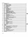
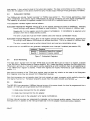
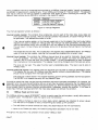
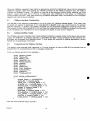
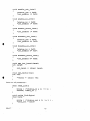
Contents
Installation Warning
1
2
The IMS B014
3
Introduction to the VMEbus'
3.1
VMEbus Terminology
3.2
VMEbus Certification
Transputer Background
4
4.1
INMOS Links
4.2
TRAMs
5
VMEbus Interface
5.1
Accessing the Board
Link Interface
5.2
5.3
Subsystem Interface
5.4
Error Monitoring
5.5
Interrupts
5.6
VMEbus Reset and link reset
5.7
VMEbus Interface Configuration
Address Modifier Codes
5.8
Programming the VMEbus Interface
5.9
Operating without the VMEbus interface
5.10
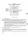
- -..TRAM
. . . . . ~~---::...-----=----------------------------1-:-=7
6
slots
4
5
5
6
6
7
7
7
9
9
10
12
12
12
13
14
14
14
16
e
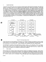
----S-.1---T-R-A-M-N-e-t-w-o-rk--------------------------1~7-
7
8
9
10
A
B
C
D
E
F
DRAFT
6.2
Secondary Link Switching
6.3
The IMS C004
6.4
Network Configuration Processor
6.5
C004 Reset
6.6
Affect of the IMS C004 on link bandwidth
6.7
Dynamic Connection Changing
System Services
7.1
Error LEDs
7.2
Driving Services Signals
Connectors
8.1
Cables
Configuration
9.1
VMEbus address selection
9.2
Link Speeds
9.3
ConfigUp and ConfigDown
9.4
Services
9.5
Secondary Link Switching
Example Setup
Glossary
Handling
B.1
Installing the IMS 8014 in a VMEbus card-cage
B.2
TRAM Installation
B.3
Installation of a TRAM with subsystem pins
Mechanical and Thermal Details
C.1
Mating Connectors
Electrical Details
0.1
Power Supply
0.2
Board-to-Board Link Connections
0.3
Non.. Local Link Connections
Connector Pin Assignments
~
Cable types
2
18
19
19
21
22
22
23
23
24
26
27
29
29
31
31
31
32
33
34
35
35
35
35
37
37
39
39
39
39
40
43