1
Table of Contents
Introduction ............................................................................................................................................ 2
Purpose .................................................................................................................................................. 2
Game Description .................................................................................................................................. 2
How to Play ............................................................................................................................................ 2
Game Features ...................................................................................................................................... 3
Overview ............................................................................................................................................ 3
Graphical Features ....................................................................................................................... 3
Gameplay Features ...................................................................................................................... 3
Individual Reports & Feature Descriptions ...................................................................................... 3
Sebastien Couture ........................................................................................................................ 3
Ryan Wallace .............................................................................................................................. 18
Nicholas Jakobsen ..................................................................................................................... 23
Julie Cho ..................................................................................................................................... 25
Performance......................................................................................................................................... 26
Software Architecture .......................................................................................................................... 26
Game Code Flow Diagrams ........................................................................................................... 26
Initialization Phase...................................................................................................................... 26
Render Function ......................................................................................................................... 28
Overall Module Structure ................................................................................................................ 29
Detailed Module Structure .............................................................................................................. 29
Math Module ............................................................................................................................... 29
Texture ........................................................................................................................................ 30
GUI .............................................................................................................................................. 31
Model ........................................................................................................................................... 33
Terrain ......................................................................................................................................... 35
Skybox......................................................................................................................................... 36
GameState .................................................................................................................................. 36
Collision ....................................................................................................................................... 37
Camera........................................................................................................................................ 38
AI.................................................................................................................................................. 38
PowerUpInfo ............................................................................................................................... 39
Appendices .......................................................................................................................................... 40
Story Overview ................................................................................................................................ 41
OpenAL Sound Example Program ................................................................................................ 42
Table of Figures
Figure 1: Method used to store terrain data from a .RAW heightmap file. ........................................ 4
Figure 2: Initial results of the terrain loader in wireframe mode. ........................................................ 5
Figure 3: Initial results of the terrain loader with a single texture....................................................... 6
Figure 4: Results of the terrain loader with static lighting. .................................................................. 7
Figure 5: Results of multi-texturing based on inclination applied to the terrain. ............................... 8
Figure 6: Results of multi-texturing based on elevation applied to the terrain. ................................. 8
Figure 7: Initial results of adding an Octree to the terrain loader. Each bounding box represents
the volume of a single node in the Octree. ............................................................................... 10
Figure 8: Skybox added to the game world ....................................................................................... 11
Figure 9: Windmill loaded with .DMF file loader. ............................................................................... 12
Figure 10: Character loaded and animated with .MD2 file loader.................................................... 13
Figure 11: Finite state machine used to handle the animation of the main character from user
input. ............................................................................................................................................ 14
Figure 12: In-game GUI screens. ....................................................................................................... 15
Figure 13: Determination of collision between a sphere and a plane.............................................. 16
Figure 14: Flow diagram for collision detection implemented in the game. .................................... 17
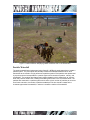
Figure 15: Example of monsters coloured with their unique colour used for colour picking. ......... 18
Figure 16: AI Characters Path finding towards Main Character....................................................... 20
Figure 17: Main Character Displaying Death Animation Due to Life Exhaustion............................ 21
Figure 18: Particle Waterfall................................................................................................................ 22
Figure 19: In Game Power-up Item .................................................................................................... 23
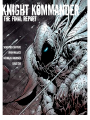
Figure 20: Opening GUI Screen ......................................................................................................... 25
Figure 21: Main steps required in initializing the game..................................................................... 27
Figure 22: Render loop of the game .................................................................................................. 28
Figure 23: Module Diagram ................................................................................................................ 29
Figure 24: Math Class Diagram.......................................................................................................... 30
Figure 25: Texture Class Diagram ..................................................................................................... 31
Figure 26: GUI Button Script Loader Format..................................................................................... 32
Figure 27: GUI Class Diagram............................................................................................................ 33
Figure 28: MD2 Script Loader Format................................................................................................ 34
Figure 29: Model Class Diagram ........................................................................................................ 35
Figure 30: Terrain Class Diagram ...................................................................................................... 36
Figure 31: Skybox Class Diagram...................................................................................................... 36
Figure 32: GameState Class Diagram ............................................................................................... 37
Figure 33: Collision Class Diagram .................................................................................................... 37
Figure 34: Camera Class Diagram..................................................................................................... 38
Figure 35: AI Class Diagram............................................................................................................... 39
Figure 36: PowerUp Class Diagram................................................................................................... 39
1
Introduction
This report is intended to describe the product produced for the EECE 478 Video Game Project,
as well as the process involved in its creation. The discussion will focus on the graphical and
game play features implemented, as well an overall description of the game and how to play it.
Additionally, possible future extensions to the game as well as their initial development plans will
be discussed.
This report will also encapsulate the individual project contributions by organizing the features
implemented by their primary implementer, along with a description of the feature written by the
creator.
Finally, this report will attempt to capture the software architecture of the game by providing an
overall module structure, as well as more detailed module class diagrams.
Purpose
This report was created in order to satisfy the project report requirement of the EECE 478 Video
Game Project.
It is hoped that the design rationale provided in this document will allow the markers of this
project to see not only what the group accomplished but also how they accomplished it. This
document will also serve as a review of the functionality and graphical features of the game, as
well as a brief user manual which will compliment the included source code.
Additionally, this report is also meant to satisfy the individual project log component of the EECE
478 Video Game Project.
Game Description
The game, Knight Kommander, is basically an adventure game with role playing elements. The
object of the game, which is given to the user in a conversation with a non playable character, is
to kill all the enemy characters within a given time limit and without dieing. Once this conversation
has taken place, the main phase of the game begins.
The main character is given a limited amount of life to complete the mission and losing all the life
before the completion of the mission results in a game over screen being displayed. The game is
single player and all the enemy characters are AI controlled.
In order to enhance the game play, multiple power ups with different effects have been scattered
around the world for the use of the main character. Moving over these power ups results in the
activation of the power up as well as a message on the screen indicating what the effect of the
power up will be.
Completing the mission in the allotted time results in a level completion screen being displayed,
while not completing the mission in this allotted time results in a game over screen being
displayed.
How to Play
The game play controls for Knight Kommander are fairly simple and intuitive. Movement in the
game is accomplished through a combination of the ‘w’ key on the keyboard for forward
movement and either the ‘a’ and ‘d’ keys or the mouse for character rotation. Additionally, the
spacebar performs a jump command and the left mouse button performs an attack command as
well as a selection command.
2
In order to attack an enemy character, the main character must first come within range of the
enemy and then select the character using the left mouse button. Repeatedly clicking on this
enemy will cause the main character to continue attacking this character until eventually the
enemy’s life is exhausted at which time they will die and disappear from the world.
Game Features
Overview
Graphical Features
•
•
•
•
•
•
•
•
•
•
•
•
•
Multi-textured Terrain
View Frustum Culling
Sky Boxing
Static and Animated Models
User Interface
Heads Up Display
Particle Systems
Precompiled Light-mapping
Team Created Custom Models
Occlusion Culling
Translucent Water
Distance Obscuring Fog
Third Person Camera
Game Play Features
•
•
•
•
•
•
•
•
•
Collision Detection
Character Selection
Multiple Enemy Types
A* Path finding with Dynamic Collision Avoidance
Character State Altering Power-ups
Non Playable Character Interaction
Time Dependant Mission Objectives
Mouse and Keyboard Interaction
Defined Mission Objectives with Completion Feedback
Individual Reports & Feature Descriptions
Sebastien Couture
Terrain Loader
Rationale
A terrain loader is essential for any land based game; as a result, it was the first module I
implemented into the game. Two options were considered for implementing the terrain loader:
• Loader using .RAW height map
• Loader using .3ds file
I decided that the terrain loader would be implemented with a .RAW height map loader since
.RAW height maps are easy to manipulate to create game levels.
3
Implementation
The terrain loader was implemented with the following steps
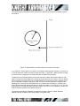
• Load .RAW data file and store the data into an array.
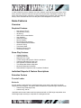
• Create an N x N array where each element in the array stores a (x, y, z) value. The
orders in which the elements in the array are stored are shown in Figure 1.
• For each triangle the normal of each vertex was determined by summing up the four
normals that can be determined at a single point. For example at point P1 in Figure 1,
one of the four normals is (P2-P1) X (P5-P1). A normal for each vertex is determined for
per-vertex shading.
Figure 1: Method used to store terrain data from a .RAW height map file.
The figure below illustrates my results of creating the terrain loader with terrain drawn in wire
frame mode.
4
Figure 2: Initial results of the terrain loader in wire frame mode.
The initial results of creating the terrain loader and applying a single texture were not impressive.
It was difficult to distinguish the features of the terrain since there was no lighting, adding an
OpenGL point light source improved the visual quality of the terrain. However, the performance
was extremely poor since for every frame the lighting for each vertex had to be determined. For a
512 by 512 terrain using a single OpenGL point light source the fps of the application was
approximately 20. The following screenshot shows the results of the initial implementation of the
terrain loader with a single texture. No lighting is applied to the terrain in the screenshot.
5
Figure 3: Initial results of the terrain loader with a single texture.
To improve the performance, static lighting was implemented. Static terrain lighting was
implemented with the Lambertian lighting model. The colour of every vertex on the terrain was
determined by using the normal of the vertex and the direction vector of the light source to the
vertex. The results are shown in Figure 4.
6
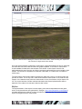
Figure 4: Results of the terrain loader with static lighting.
The performance improved by a factor of two by implementing static lighting instead of using
OpenGL lighting. There is an increase in performance because the colour of each vertex due to a
light source is only determined once, while with OpenGL lighting the colour of each vertex due to
a light source is determined every frame.
Applying static lighting to the terrain improved the visual quality of the terrain; however, it still did
not look realistic since only a single texture was being used. To improve the realism, multitexturing using OpenGL ARB extensions was implemented. Multi-texturing is implemented by
specifying the input and output of the graphic cards texture units. Almost all graphics cards now
support a minimum of four texture units (most new graphics cards now support 8 texture units).
To not limit our game to only users with new graphics cards, I decided to implement multitexturing using at most four texture units. A tutorial at
http://www.delphi3d.net/articles/viewarticle.php?article=terraintex.htm was used to setup multitexturing using the OpenGL ARB extensions. The two screenshots below illustrate the addition of
multi-texturing to the terrain.
7
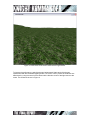
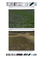
Figure 5: Results of multi-texturing based on inclination applied to the terrain.
Figure 6: Results of multi-texturing based on elevation applied to the terrain.
8
View Frustum Culling
Rationale
View frustum culling using an Octree was implemented next since the fps of the terrain loader
using multi-texturing on a 256 by 256 terrain was approximately 70 fps, but with a 512 by 512
terrain the fps dropped to below 30 fps. A simple option to improve performance is to reduce the
z-far distance of the view frustum; however, the visual realism of the scene diminishes. A better
solution is to implement view frustum culling. Two options were considered for view frustum
culling:
• Culling using a Quadtree.
• Culling using an Octree.
A Quadtree recursively subdivides the terrain into 4 quadrants, while an Octree recursively
subdivides the terrain into 8 quadrants. I decided to implement culling with an Octree because it
performs better with “hilly” terrains since an Octree subdivides along the y-axis, while a Quadtree
does not.
Implementation
The Octree was implemented using a recursive approach. The terrain is first subdivided into 8
nodes, and is then recursively subdivided. The recursion of a node stops when either the max
tree depth is reached, or the number of triangles in a node is less than a defined number. The
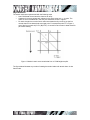
screenshot below shows the bounding boxes of the nodes in the Octree. In the screenshot no
max depth was specified and the maximum number of polygons in a quadrant was specified at
2000 (i.e. inside the bounding box volume there is a maximum of 2000 polygons).
9
Figure 7: Initial results of adding an Octree to the terrain loader. Each bounding box represents
the volume of a single node in the Octree.
Once the Octree had been implemented, view frustum culling was applied so that only nodes that
are inside the view frustum are sent down the graphics pipeline. The number of view frustum
checks needed is limited due to the structure of the Octree. A view frustum check is first
performed with the root of the tree, and is then recursively performed if the root is inside the view
frustum. The recursion is stopped once it reaches a leaf node, or a node that is not inside the
view frustum.
The performance of the terrain loader improved from 30fps with a 512 by 512 terrain map to 60
fps with an Octree. This is only true in most cases where the entire terrain is not inside the view
frustum. In the extreme cases, when the entire terrain is in the view frustum, the fps drops to 2025. This occurs because of all the overhead calculations the Octree implementation does to
determine if the nodes in the tree are inside the view frustum.
Skybox
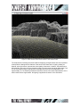
The implementation of the skybox involved creating a box that encapsulates the entire game
world. Six skybox textures were generated in Terragen ( http://www.planetside.co.uk/terragen/)
and were applied to the inside of a cube to provide the illusion of a sky. The result of adding a
skybox to the game world is shown below.
10
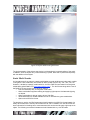
Figure 8: Skybox added to the game world
The implementation of the skybox was simple, but it dramatically increased realism of the world.
In addition, since the skybox only involves texturing 6 quads, there was no performance penalty
with the addition of the skybox.
Static Model Loader
An important part of any game is a static model loader to render buildings and other static models
in the game. There exists many file formats for static models such as .obj, .3ds, .max, .lwo, etc.
However, I decided to create a model loader for .dmf files. DMF files are created in a free game
model editor called DeleD LITE (http://www.delgine.com/ ). The .dmf format along with the use of
the DeleD LITE was chosen for the following reasons:
• Free and extremely easy to use game model editor.
• Game model editor supports creating and applying light maps to simulate static lighting
on objects.
• Game model editor is able to import .obj and .3ds files.
• Varied assortment of models available for free of use within the game model editor.
• Open source ASCII file format.
The decision to use the .dmf file format was primarily based on its ASCII file format instead of a
binary file format which is used by file formats such as .3ds. In addition, the .dmf file format can
store information for blending two or more textures which can be used to apply a light map to an
object. The following screenshot illustrates a windmill loaded with my .dmf file loader.
11
Figure 9: Windmill loaded with .DMF file loader.
To ease the use of the .DMF file loader with the creation of the game world, a script loader was
created. The script loader loads a custom ASCII script file format. In the file, different models can
be specified along with their location, rotation and scale in the game world.
Animation Model Loader
Several animation model file formats were considered for animating characters and objects in our
game world. Most current animation model file formats use bone animation along with quaternion
math. Due to time constraints, I decided to use the .MD2 file format which was used in Quake2.
The reasons for choosing the .MD2 file format are:
• Simple binary file format
• Open source code (The source code for the entire Quake 2 game can be downloaded
and studied)
• Excellent tutorials on creating .md2 loaders (http://tfc.duke.free.fr/)
• Over 2000 models that can be freely used in-game.
(http://planetquake.gamespy.com/quake2/ ). Each model has 21 animations (run, stand,
attack, pain, etc.).
• Low polygon count; .md2 files have a constraint on the number of polygons that can be
used in the model. As a result, for new computers there is no performance decrease
when rendering many .md2 models on the screen.
I do not take full credit for creating the .MD2 model loader since many parts of the loader; most
notably, loading the model data from the binary file was taken from a tutorial at
http://tfc.duke.free.fr/. The following screenshot illustrates an .MD2 file loaded using the model
loader.
12
Figure 10: Character loaded and animated with .MD2 file loader.
A major difficulty with using the created model loader in the game was implementing the transition
between animations due to user input. The following finite state machine was implemented to
handle stand, run, jump, and attack input from the user.
13
RUN
STAND
S2 / ANIM = RUN || ATTACK
RUN
S1/ ANIM=
STAND
STAND
STAND && ANIM_DONE
RUN
RUN && ANIM_DONE
JUMP
ATTACK
STAND && ANIM_DONE /
JUMP
ATTACK
S4/ ANIM =
ATTACK
S3/ ANIM =
JUMP
JUMP
ATTACK && ANIM_DONE
Figure 11: Finite state machine used to handle the animation of the main character from user
input.
GUI
My GUI implementation took a significant amount of time, and in the end it is more advanced then
it needed to be for the game, since only buttons and displaying static text were required. The GUI
API I created has the following functionality:
• Create and display main, and child windows which have a background texture and a title
bar.
• Create and display buttons which have an up/down state.
• Create and display static text in a window.
• Create and display a scroll bar in a window.
• Create and display scrollable text fields.
My implementation of the GUI emulates several function calls for win32 GUI programming, such
as for creating windows. But most of the functions to display and update text emulate SWING
GUI calls which are used in java programming.
The only significant difficulty with programming the GUI for the game was determining when a
button was pressed. Two options were considered:
•
Colour picking in which the button selected is determined by the colour of the pixel
directly underneath the mouse cursor when the mouse button is pressed. To differentiate
14
•
between GUI buttons, the scene is re-rendered when a mouse button is pressed and
each GUI button is rendered with a solid unique colour. The user does not see the GUI
buttons being rendered with a distinct solid colour, because the back and front buffers are
not swapped in the process.
Mouse position in which every movement of the mouse is recorded by the GUI, and the
GUI screen is updated according to the mouse position.
Colour picking is far easier to implement, but it only allows the GUI to update when a mouse
button is pressed. As a result, I decided to implement the GUI buttons using a mouse position
scheme since this allowed me to update the buttons when a mouse is pressed but also when the
mouse is moved over a button. The following figure illustrates a parent window with two buttons
(Main Menu, and Exit), and a child window with two buttons (Ok and Cancel).
Figure 12: In-game GUI screens.
Collision Detection
One of my final tasks was to implement collision detection. Collision detection is integral to my
team’s game since the world is filled with buildings and trees. The game required collision
detection between the main game character and the static objects in the world. In addition, my
collision detection implementation is used to handle collision detection between the main
character and monsters in the game world.
The collision detection was implemented using a bounding sphere for the main character and a
bounding box for the static objects in the world. Bounding box collision for the static objects is
adequate since all objects except for the trees in the world have a shape of a box.
15
The following figure illustrates the basic principles of determining the collision between a sphere
and a plane.
Figure 13: Determination of collision between a sphere and a plane.
If | (C0-P0) ·N| > R then there is no collision of the sphere with the plane. However, if |(C0-P0) ·N|
=< R then there is a collision of the sphere with the plane ; in particular, if the dot product is equal
to R then there is a single point of contact between the sphere and the plane.
To determine if the bounding sphere of the main character collides with the bounding box of an
object; the sphere is tested against four planes of the bounding box of an object. Only four planes
of the six planes of the bounding box are tested because at no time will the main character be on
top or underneath an object in the game world. There is a collision between the spheres with a
bounding box if and only if for each plane there is a collision with one plane (i.e. |(C0-P0) ·N| =<
R) and for the three other planes the sphere is “behind” the plane (ie. (C0-P0) ·N =< -R). This can
be simplified to checking each plane with the condition: (C0-P0) ·N =< R to determine if there is a
collision between the sphere and the bounding box.
The following flow diagram illustrates the sequence of steps to perform collision detection
between the main character and a single object in the game world.
16
Calculate the
next potential
position of the
main
character
(P1)
Collision
Counter = 0
Collision
Counter == 4
?
NO
YES
PLANE =
Next
Bounding Box
Plane
Collision of
sphere (/w
center == P1)
with PLANE
?
YES
Collison
Counter++;
NO
Next position
of the main
character =
P1
Next position
of the main
character =
current
position
Figure 14: Flow diagram for collision detection implemented in the game.
When collision detection was added to our game world; which consists of 45 static buildings
(including trees), there was only a small decrease in performance by approximately 5 fps
However, to allow our game to be more scaleable, a collision detection check with an object is
only performed if the object is in the view frustum, and if there is a collision between the bounding
sphere of the main character with the bounding sphere of an object. A collision between two
spheres is checked by determining the distance between the centers of the two spheres. Adding
the view frustum check along with the bounding sphere-sphere collision detection test eliminated
any performance decrease with 45 static buildings in the game world.
Model Selection
My final task involved determining a method to select monsters and other characters in the game
world. Colour picking was used to implement model selection in the game world because of its
simple implementation, and its high resolution of accuracy (accuracy on the order of a single
pixel).
Colour picking was implemented for whenever the user pressed the left mouse button. When the
left mouse button was pressed then the scene was re-rendered. The only parts that are rerendered are the game world monsters and characters. However, the game world monsters and
17
characters are only rendered with a single unique colour. The following screenshot illustrates the
concept.
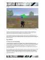
Figure 15: Example of monsters coloured with their unique colour used for colour picking.
However, the user never sees the above screen in the game when the left mouse button is
pressed since the solid colour game monsters are only rendered in the back buffer, and the
buffers are never swapped while the monsters are coloured a solid colour.
Once the game monsters and characters have been rendered with a unique solid colour, the
colour under the mouse button is determined using an OpenGL call to read the pixel colour. Once
the pixel colour is known, it can easily be determined which (if any) game monster or character
has been selected.
Ryan Wallace
AI Characters & Path finding
The AI characters in the game were constructed using an Object Oriented paradigm which
provided abstraction, modularity, and modifiability. Each character was enclosed in its own object
which provided all the variables and methods used in path finding, character state (discussed in
the next section), and character rendering. Additionally, in the main game logic file, the AI
characters were stored as a linked list, allowing characters to be easily added and removed on
the fly during the game.
Each AI character had two major modes of operation. When the main character was out of range,
the character was made to follow a predefined path marked by an arbitrary set of waypoints.
When the main character entered the range of the AI NPC, the character was transitioned to a
chase mode, in which the AI NPC plots a path to the main character and once within a certain
range, begins attacking.
18
The AI path finding was implemented using the industry standard A* algorithm. A* (A star) is used
to find the optimal path for the character to its destination. This optimal path takes into
consideration obstacles that have been marked unwalkable such as hills, buildings, water, and
other AI monsters. In addition, the algorithm takes into account the height of the terrain as an
added terrain cost to encourage the characters to walk along the roads of the world. The desired
destination is dependant upon the state of the character (whether patrolling or chasing). Because
A* algorithm requires that the world is broken down into tiles, each area of the 512 by 512 map
was considered a tile. This allows all AI characters to roam freely over the whole world.
One of the challenges of implementing the path finding algorithm was including dynamic
avoidance of other moving characters. In order to achieve this, each character’s walkability array
was modified every step with the locations of the other AI characters. This made it necessary to
recalculate the path of the character at every step of the algorithm. In order to optimize for
performance, this requirement was slightly modified for the patrolling state (see below).
Another of the challenges of implementing the path finding algorithm was optimizing the
performance such that at least 20 AI characters with path finding capabilities could be included in
the world at one time. This was a very challenging problem that was tackled using a variety of
techniques. Firstly, quick checks were made at the beginning of the path finding function to
ensure that a path needed to be found. Secondly, when the character was in the patrolling state,
the path was only calculated once at each waypoint along the path. This requires that the
characters follow non overlapping patrol paths in order to prevent undetected collisions between
AI characters. Thirdly, a heuristic was used that if eight AI characters were already chasing the
main character the remaining characters were held in the patrol state so that a maximum of eight
characters (enough to surround the main character) were recalculating their path every frame.
A final major hurdle of the path finding process was creating the illusion of a smooth path when in
fact the character was always moving in straight lines towards the target. This was accomplished
by giving each character an angular velocity and turning them at a constant rate towards the
desired angle. If the desired angle was greater than 45 degrees the character was stopped and
rotated to avoid the appearance of walking in an unnatural direction.
19
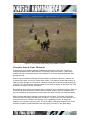
Figure 16: AI Characters Path finding towards Main Character
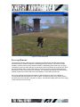
Character State & Game Mechanics
At the beginning of the game (although modifiable throughout the game) each character is
assigned parameters which determine their life, damage, speed, and location. These states
enabled both the AI characters and the main character to move at an appropriate speed, deal
damage, and die.
When the game decides that damage should be dealt to a character a function is called in the
character object which is being hit to deal with the strike. This approach allows different ways of
dealing with the damage, and would allow a blocking mechanism to be easily implemented given
more time. This also allows the character object to mark itself for deletion by the game logic if the
character’s life supply has been exhausted.
One challenge encountered was deciding when to register a hit on a particular character. Each AI
character was given functions to indicate if they were within range of the main character and if
they were attacking. Changing these functions allows the ability to tweak how characters attack.
Each character object also wraps the model used by the character. This model is sometimes
called from within the object to display pain animations, or in the case of the main character, it is
sometimes called from outside of the object by using a getModel() function for things like
displaying run animations upon key press. This is an artifact of the game design and the model
would be completely encapsulated within the object given more time for the game design.
20
Figure 17: Main Character Displaying Death Animation Due to Life Exhaustion
Particle Waterfall
The particle waterfall was implemented using OpenGL’s ARB point sprite extensions to create a
particle system. The point sprites are basically hardware accelerated billboards which lend
themselves to the creation of high performance particle systems. Each particle was represented
by a point sprite and encapsulated in a particle object which contains its position, velocity, and
acceleration. The particles also feature basic collision detection which allows them to “bounce”
when they reach a certain level, creating the bubbling effect seen in the screenshot below. The
particles are contained in a particle system which emits a given number of particles per unit time.
As a future extension, the number of particles emitted per unit time should increase as the
character approaches the waterfall, in order to increase the realism of the waterfall.
21
Figure 18: Particle Waterfall
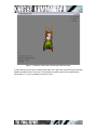
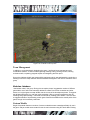
Power-up Elements
The power-up elements made use of the modularity provided by the character state classes
described above to create an additional interesting game play element. The power-ups were
created in a similar manner to the character classes, encapsulating each power-up in an object,
including the power-up model and type as well as the rules for the effects of the power-ups. When
the main character was in range of the power-up it’s pick up function would be executed which
would perform some effect on the main character. The modularity provided by the class allowed
multiple models to be used as well as the rapid addition of new types of power-ups.
One major challenge was creating the power up state machines in order for the effects to
correctly display their messages on the GUI screens. This was solved by using distinct phases
and saving the current phase in the power up object. This allowed multiple power-ups to be acting
on the character at any one time.
22
Figure 19: In Game Power-up Item
Team Management
In addition to my duties directly developing the game, I performed some management and
coordination activities. These included organizing meetings, taking meeting minutes, sending
reminder emails, requesting progress reports and integrating the final report.
One major challenge initially was responsibility assignment which was addressed by conducting a
meeting in which the major features were discussed and assigned to the various individuals in the
group.
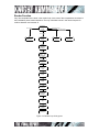
Nicholas Jakobsen
I had several roles in the group. During the conception phase I suggested a number of different
game ideas, one of which we eventually decided to create. Due to time constraints and other
factors, our original game concept shifted over the course of the development phase. Throughout
the development period, my role was mainly art design. With my previous experience with 3D
modeling and graphics design, I was able to contribute by creating game assets. I was also able
to suggest methods of implementing certain game functions that added to the overall polish of the
game, though I did not directly code them.
Custom Models
Knight Kömmander features a number of custom models that were created specifically for use in
the game. Player models were created for use the main character using 3D Studio Max. Existing
23
models were imported into 3D studio in order to capture their animation. Since the models were
MD2 quake models, there was no skeletal system to create new animation from. Therefore
objects were attached to the model faces allowing them to follow the motion of the model’s
animation. Weapons and armor were modeled and attached the main character model and were
exported to Misfit Model 3D in order to combine the individual model animations into one MD2
file.
This process was successful, however, when the model was textured, it became apparent that
the model’s normals were not being exported correctly by the Max MD2 exporter. Because of this,
our initial storyline and game play plans were altered. Instead of the Pope as the main character,
we used the knight model on which the Pope’s model was based.
Static models were also modeled in 3D Studio and exported to the 3DS file format and then
converted to DMF files in order to use them in the game.
Motion Blur Effect
To enhance the visual aspect of power-ups and debuff items in the game, I attempted to create a
motion blur effect using the back buffer and rendering to textures. The final rendered scene was
to be copied from the back buffer to a texture placed on a quad in front of the camera. The quad
generation would be repeated, each time shrinking the texture coordinates, thereby causing the
image to appear to grow. The combination of a low resolution texture and semi-transparent quads
created the illusion of a blurred image that was melting towards the camera. This attempt was
almost successful in that I was able to set up the effect using a pre-rendered texture, however,
when attempting to copy the scene from the back buffer, the texture was blank and the effect was
eventually abandoned.
Lens Flare Effect
I also attempted to create a lens flare effect. By specifying a point in 3D space I used OpenGL
functions to estimate the location an object drawn at that position would project onto the view
plane. By testing the Z-buffer depth of the object and the Z-buffer depth at the same screen
position at the end of the display function, I could determine whether or not the object was
occluded. Using this information I could decide whether or not to draw the lens flare. If an object
was between the camera and the lens flare’s light source, the flare would not be drawn. Next, the
angle and position of each element in the lens flare was calculated based on the between the
view frustum and the light source. The position of the lens flare would then be set so that the
effect always appeared in front of the camera. In practice however, I could not get the lens flare to
draw in front of the camera before the game was to be submitted and therefore the effect was
also abandoned.
Scene Graph
To optimize the frame rate of Knight Kömmander, I created a scene-graph class in which we
would attach all static objects. The class allowed nodes to be created and moved as well as
bounding boxes to be resized based on the location of objects in the node’s child branches. The
class was built very early in the construction of the game and a number of key classes and
functions had not yet been completed, namely the bounding box class and the collision detection
function. The collision detection function would be used on a per vertex basis to determine if a
child node’s bounding box protruded outside its parent’s. Because the collision detection function
was not completed until much later, the scene graph was put on the backburner and eventually
scrapped due to the changing visual requirements of our game.
24
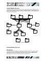
GUI Screens
I created the GUI screens for Knight Kömmander using Paint Shop Pro. Several GUI’s were
created, one for each new game idea. Initially the game was entitled Tank Kömmander, then
Pöpe Kömmander, and then finally Knight Kömmander. For Knight Kömmander, I used images
found on the internet and composited them into the GUI. Other GUI elements like buttons were
created, but never implemented due to time constraints.
Figure 20: Opening GUI Screen
Julie Cho
Collision Detection
There were many changes to the collision detection throughout the development of the game.
Initially, the game was supposed to have tanks that would shoot at each other. For this design,
the collision detection was a box-box detection as tanks have a more squared shape. To do this,
I had initially made boxes out of squares. The distances for the each square relative to another
had to be calculated. The collision detection for the box-box model worked fairly well except that
detection at the corners was not consistent.
Next, I implemented a sphere-sphere collision detection model. This was simpler to implement
than the box-box collision detection model as there were less calculations to compute. The
collision function would return true if the centres of the two spheres was less than or equal to the
radius of one circle plus the radius of the other circle.
25
And finally, the game changed to require a sphere-plane collision detection model. To calculate
the collision, I had this function:
float distApart = dotProduct (plane1.normal(), sphere.centre());
if (distApart > sphere.radius())
return false;
else return true;
This function would return true if the distance of the centre of the sphere from the plane was less
than the radius of the sphere. I had troubles making a plane and calculating the normal of the
plane. Sebastien took over from here.
Sound
Adding sound to the game was attempted but it did not get integrated. With OpenAL, three
components go into playing a sound. Firstly, there are the sound buffers that store all the
information on how a sound should be played. Secondly, there needs to be the sound data itself,
and lastly, there needs to be a source (a point in space) that emits a sound. Included in the
appendices is the code for a very basic sound program was implemented using the OpenAL API.
It contains a loop the plays the sound data for water flowing. The volume for the water flow is
controlled by the distances the source is from the listener; the farther away the source is from the
listener, the quieter the sound gets. Initially, I wanted the sound of the waterfall to get louder as
the player gets close to the water and conversely, softer as the player gets further away. Also,
when the player swings the sword, I wanted a swish sound to correspond to the action.
Performance
At the time of the demo, the game was running at about 35 to 40 frames on a 3 year old laptop,
and about 100-150 frames on an average current desktop system. Due to the significant amount
of performance tuning that was performed on the game, the frame rate was never seen to drop
below an acceptable level, even with most of the advanced graphical features on the screen
simultaneously.
Software Architecture
Game Code Flow Diagrams
Initialization Phase
The initialization phase of the game takes approximately seven seconds on a new computer
because of the terrain loading; in particular the creation of the Octree for view frustum culling.
26
C ompute
w aterfall
properties
Initialize
camera
Load the
terrain data
C ompute
terrain static
lighting and
multi - texturing
information
Load static
model data
C reate
display lists
for the static
models
Load
animated
.md 2 models
Initialize AI of
the animated
monsters
Initialize
pow er up
infomation
Setup fog
settings
Figure 21: Main steps required in initializing the game
27
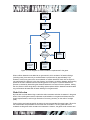
Render Function
Very few computations are done in the render loop; since most of the computations were done in
the initialization phase mentioned above The only calculations done in the render loop are for
collision detection and monster AI.
Main Screen
D etermine
w hich game
screen
currently in
Game Over Screen
“You Win” Screen
Game Screen
R ender main
screen GU I
Set the
camera
position
R ender game
over GU I
R ender “You
Win” GU I
Perform
collision
detection
calculations
Move the
camera
position , and /
or orientation
(if needed )
R ender the
main
character
R ender the
terrain and
w ater
R ender
skybox
R ender static
models
C ompute
monster AI
R ender
animated AI
monsters
R ender pow er
ups
R ender
w aterfall
R ender game
screen GU I
Figure 22: Render loop of the game
28
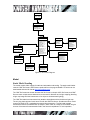
Overall Module Structure
The following diagram presents the structure of the modules used to create the game as well as
the dependencies between the various modules. In the following section, a detailed description of
all the modules presented here is given, including the classes contained in each module and the
responsibility of those classes.
Model
Terrain
GUI
Skybox
Camera
Texture
Math
Waterfall
Mouse
Collision
Detection
AI
GamestateI
nfo
PowerUpInf
o
Figure 23: Module Diagram
Detailed Module Structure
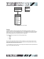
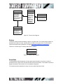
Math Module
The math module offers operations for math involving Cartesian vectors. The module includes
basic operations such as: add, subtract, dot product, and cross product. In addition, the math
module offers a class for storing triangle and point information. The math module has been
tested, and there have been no bugs found with any of the operations.
29
glPoint
glTriangle
-m_point[3]: glVector[]
+setTriangle()
+getTriangle()
-x: float
-y: float
-x: float
1
1
glVector
+operator +()
+operator -()
+operator *=()
+operator =()
+operator *()
+CrossProduct()
+DotProduct()
+Normal()
+NormalLength()
+RotateY()
+Length()
Figure 24: Math Class Diagram
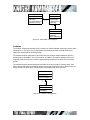
Texture
The texture module is useful for any task which involves texturing an object in a game. The
module is centered on the TextureManager class. The TextureManager class uses the Singleton
design pattern; only a single TextureManager object can be created. This is required since the
texture manager keeps track of all textures used in the application.
The texture module has support for the following image formats:
• .BMP
• .JPEG
• .PCX
• .RAW
• .TGA
None of the file image loader classes have been created by our group. But the creators of the
image loader classes allow the classes to be freely used, but do not guarantee that the classes
will work and are not at fault if they do not work.
The TextureManager class along with all of the image loader classes has been fully tested and no
bugs or memory leaks have been found.
30
TGA
JPEG
+LoadFileTGA()
+JPEGTexture()
RGBRaw
1
1
+LoadRGBImage()
1
1
1
TextureManager
+Instance()
+LoadTexture()
+QuickLoad()
1
PCX
1
1
+LoadFilePCX()
1
1
1
BMP
ARBWrapper
1
+LoadFileBMP()
+DisableTexture()
+EnableTexture()
+ARBModelSetup()
+ARBTerrainSetup()
+ARBExtension()
+glActiveTextureARB()
+glMuitiTexCoord2fARB()
+glClientActiveTextureARB()
Figure 25: Texture Class Diagram
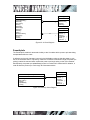
GUI
The GUI module has been designed to offer a basic API to create and display GUIs in-game. The
GUI module could be used in any game. The GUI module offers the following functionality:
•
•
•
•
•
Create and display parent and child windows
Create and display buttons. Two images need to be specified for each button.
o one to represent the “up” state
o another to represent the “pressed” state of the button
Create and display a single static text box
Create and display a scrollable static text box
Create and display a scroll bar
To ease the use of modifying and placing buttons on the game screen, a simple script loader and
format were created. The format is described below.
31
SC Buttons V1.0;
// Indicate version
// required space; but anything can be placed in the line
6;
// number of textures
0; BUTTON_UP; BUTTONUP.bmp;
// texture ID, texture name, texture filename
1; LEFT_UP; LEFTUP.bmp;
2; RIGHT_UP; RIGHTUP.bmp;
3; BUTTON_DOWN; BUTTONDOWN.bmp;
4; LEFT_DOWN; LEFTDOWN.bmp;
5; RIGHT_DOWN; RIGHTDOWN.bmp;
// required space
2;
// number of buttons
// required space
0; 1; Terrain;
// Button ID, bool: has text? Text string
2; 0; 3;0,0;100,30;
// Number of textures, texture1 ID (up state), texture2 ID (down
state), minX button position,miny,maxX,maxY
1;1;Model;
2;0;3;0,30;100,60;
Figure 26: GUI Button Script Loader Format
The GUI module has been extensively tested with the game. Only the scrollable text box has a
known bug. The bug occurs when destroying a scrollable text box object. There has not been a
lot of time devoted to eliminate the bug because no scrollable text boxes were used in the game.
All other features though, do not have any known bugs, or memory leaks.
32
GUIEvent
-event : String
-screen : String
*
1
GUIEventMessages
+addEvent ()
+getNextEvent ()
+messagesAvailable ()
1
1
WindowT
Text
TextList
1
1
GameOverScreen
1
+ Display ()
+ SetWidthHeight ()
+ SetButtonState ()
1
YouWinScreen
+createWindowT ()
+createWindowTEx ()
+AttachButtons ()
+AttachTextBox ()
+AttachListbox ()
+UpdateText ()
+UpdateListBox ()
+DisplayWindow ()
+SetDisplayed ()
+isDisplayable ()
+updateState ()
+getWindowEvent ()
+getButtonFocus ()
1
1
*
-AttachListBox
-DisplayListBox
-SetListText
-SetWndInfo
*
1
*
1
Buttons
1
*
+Display ()
+SetWidthHeight ()
+SetButtonState ()
1
+AddTextBox ()
+DisplayTextBox ()
+SetText ()
+UpdateState ()
+SetBoxColour ()
+SetWndInfo ()
1
+CreateButtons ()
+CreateButton ()
+DisplayButtons ()
+UpdateState ()
+IsButtonPressed ()
1
MainScreen
+Display ()
+SetWidthHeight ()
+SetButtonState ()
GameScreen
+Display ()
+SetWidthHeight ()
+SetButtonState ()
Figure 27: GUI Class Diagram
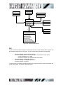
Model
Static Model Loading
The model module offers support for static and animated mode loading. The static model loader
uses the .DMF file format. .DMF files are produced from the program DeleD LITE which can be
downloaded and used for free at http://www.delgine.com/ .
The .DMF file format was chosen because the file format is a simple ASCII file format, and .DMF
files can store multiple texture data which can be used for features such a light mapping (blending
a light map image with the base texture of an object to simulate static lighting).
The .DMF file loader has been extensively tested to load objects with and without a light map.
The only bug that has been found has to do with the .DMF file format. Sometimes when a model
is saved in DeleD LITE, it capitalizes the texture format extension. The file loader created
assumes the texture format extension is always in lower case; as a result, the file loader will give
an error if the texture format extension field in the format is capitalized. To fix this problem,
33
without modifying the code, the .DMF file can be altered. The example below illustrates how the
problem can be solved.
Change the following line from:
15;Wood02;Wood;0;1;0,Wood\Wood02.JPG,1;
To
15;Wood02;Wood;0;1;0,Wood\Wood02.jpg,1;
There are no other known bugs or problems with the .DMF file loader; in addition, there are no
known memory leaks.
Animated Model Loader
The animated model loader uses the .MD2 file format. The .MD2 file format was chosen for the
following reasons:
•
•
•
•
•
Simple binary file format
Open source code (The source code for the entire Quake 2 game can be downloaded
and studied)
Excellent tutorials on creating .md2 loaders (http://tfc.duke.free.fr/)
Over 2000 models that can be freely used in-game.
(http://planetquake.gamespy.com/quake2/ ). Each model has 21 animations (run, stand,
attack, pain, etc.).
Low polygon count; .md2 files have a constraint on the number of polygons that can be
used in the model. As a result, for new computers there is no performance decrease
when rendering many .md2 models on the screen.
A significant portion of the .MD2 loader implemented was taken from a tutorial at
http://tfc.duke.free.fr/ .The source code taken from the tutorial is under the MIT license.
To ease the use of using the .MD2 model loader in a game, a wrapper class was created that
loads a script file that contains information about the .MD2 model to load. The format of the script
file is outlined below.
#MODEL
Dragon
// Model name
#MODELFILE
models/Dragon.md2
// Location of the .md2 file for the main model
#MODELSKINFILE
models/dragon_green.pcx
// Location of the texture image for the main model
#WEAPONFILE
NONE
// Location of the .md2 file for the weapon model for the character
#WEAPONSKIN
NONE
// Location of the texture image for the weapon model. Set to
NONE if there is no weapon for the model
Figure 28: MD2 Script Loader Format
The .MD2 wrapper class has been extensively tested, and there are no known bugs or memory
leaks with the source code taken from the tutorial or from the code implemented.
34
MD2Wrapper
+DrawModel( )
+DrawAnim()
+ReadFile()
+LoadModelList()
+GetAnim()
+isAnimDone()
StaticLevelModelLoader
+readModelList()
+displayModels ()
+getModelDataList()
0..*1
md2
1..*
1
+LoadModel()
+LoadSkn()
+DrawModel( )
+DrawFrame()
+SetAnim()
+GetAnim()
+ScaleModel()
+SetNextAnim()
+isAnimDone()
StaticLevelModelData
+m_name: String
+m_filename: String
+m_numInstances: int
+m_modelInfo: vector<model_data_t>
+m_model: CDeledLoad
0..*
model_data_t
+m_loc[3]: int[]
+m_scale: float
+m_rotation: float
+userdefined: boolean
1
1
1
anorms
1
1
anormtab
DeleDLoader
+LoadModelData()
+CreateModelDL()
+DrawModel( )
+GetDLStart()
+GetNumDL()
+DrawBB()
+getBB()
Figure 29: Model Class Diagram
Terrain
The terrain module loads a terrain from a .RAW image file. In addition, the terrain module
implements static terrain lighting using the Lambertian lighting model, terrain multi-texturing
based on elevation or incline, and view frustum culling using an Octree.
The terrain module uses the .RAW image file format since .RAW image files can be easily
manipulated in terrain programs such as Terragen (http://www.planetside.co.uk/terragen/) or in
paint programs to create game levels.
There are no known bugs or memory leaks with the terrain module; however, the Octree class
could be optimized. Currently, two copies of the terrain data are stored: one is in a single array;
while the other copy is stored in partitioned arrays (each partition corresponds to terrain data for a
single node in the Octree). This could be optimized by storing only pointers to indexes to the main
array in the Octree instead of storing the data. This optimization was not implemented because of
lack of time.
35
Octree
RawTerrain
+RenderHeightMap()
+RenderHMap()
+ProcessHMap()
+GetMapSize()
+RenderTerrainWater( )
+GetHeightRatio()
+Height()
1
1
1
+RenderOctree()
+CreateOctree()
+GenerateDL()
+GetNumVerts()
+GetVertices()
+IsLeaf()
+GetNormals()
+GetColours()
+GetBBSize()
+DrawBBox()
Frustrum
1
1
+CalcFrustrum()
+FrustrumCheckCube()
+UpdateFrustrumVol( )
1
TerrainLight
+GetLightPos()
+GetShadowColour()
+SetLightPos()
+SetShadowColour()
+DrawLightPos()
Figure 30: Terrain Class Diagram
Skybox
The skybox module handles rendering a skybox in a game world. The module simply applies six
textures to the inside of a cube, and the cube is rendered in the game world. The six textures
used for the skybox were generated in Terragen (http://www.planetside.co.uk/terragen/ ).
There are no known bugs or memory leaks with the module.
Skybox
+LoadSkyBox()
Figure 31: Skybox Class Diagram
GameState
The GameState module keeps track of basic game state information such as the number of
monsters left in the game to kill, and the time left to kill all the monsters. This module is specific to
Knight Kommander, and would be of no use outside of the game.
The module has been tested and no bugs or memory leaks have been found.
36
GameState
TaskGiverNPC
+updateTime()
+getTime()
+decrementGoblins()
+getGoblinCount()
+setModel()
+startDialog()
+isDialogDone()
+getText()
1
1
11
TaskGiverFSM
+setState()
+getState()
+canCrossBridge()
Figure 32: GameState Class Diagram
Collision
The Collision module handles determining if there is a collision between a bounding sphere and a
bounding box. In the game, the bounding sphere represents the main character while game
objects are represented by bounding boxes.
The module has been optimized for performance by only doing a collision detection test if the
bounding box to be tested is in the view frustum. In addition, the collision detection test is only
computed if the bounding box is within a specified range relative to the center of the bounding
sphere.
The module has been extensively tested and there are no known bugs or memory leaks. Also
there was significant amount of testing done to ensure that in-game the main character does not
ever get stuck in a game object. During testing, this problem had never occurred.
Collision
+isCollsion ()
-planeCollision ()
1
*
BBox
+setParam()
+setBB()
Figure 33: Collision Class Diagram
37
Camera
The camera module offers a class for a first person and a third person camera. The module can
be used for smooth camera movement using either a keyboard or a mouse.
The third person camera was used in the game; as a result, there has been little testing done with
the first person camera class. The third person camera has been fully tested and there are no
known bugs or memory leaks.
ThirdPersonCamera
+SetPositin()
+Move()
+RotatePosition()
+RotateUPDOWN()
+UpdateHeight()
+UpdateHeightPosition()
+Strafe()
+()
FirstPersonCamera
+ChangeVelocity()
+ChangeHeading()
+ChangePitch()
+SetPerspective()
+GetPosX()
+GetPosY()
+GetPozZ()
Figure 34: Camera Class Diagram
AI
The AI module encapsulates the state of the enemy characters as well as provides the path
finding functions needed by the characters. Each AI character has their own path finding
walkability array, which allows for the dynamic collision avoidance, as well as all the variables
needed by the path finding functions.
The set*() functions are used to setup or change the operational parameters of the AI units while
the beenHit() and is*() functions are used to take care of the attacking and defending of the
character.
The move() function is used to change the character’s position using the A* algorithm while the
render() function is used to choose the character animation as well as display the character on
the screen.
38
aiNPC
aStarAlgorithm
+initPath()
+updateWalkability ()
+setModel()
+setLocation()
+setLife()
+setSpeed()
+setDamage()
+setPatrol()
+beenHit()
+isAlive ()
+isReadyToAttack()
+isInRange()
+move()
+render()
1
+initializePathfinder ()
+endPathfinder()
+findPath()
+readPath()
1
MD 2Wrapper
1
+DrawModel ()
+DrawAnim ()
+ReadFile ()
+LoadModelList ()
+GetAnim ()
+isAnimDone ()
1
Figure 35: AI Class Diagram
PowerUpInfo
The PowerUpInfo module is structured similarly to the AI module with the power-up’s state being
encapsulated within the class.
A reference to the main character is set up in the initialization routine so that the power-up can
act on the character when it is picked up. When the character comes within range, the power-ups
pickup() method is executed which notifies the power-up to begin acting on the main character.
Subsequently, the power-ups updateState() routine is invoked until it marks itself for deletion, in
order to allow the power-up to run through its finite state machine.
MD 2Wrapper
powerUp
+setModel()
+setLocation()
+pickUp()
+updateState()
+render()
1
1
+DrawModel ()
+DrawAnim ()
+ReadFile ()
+LoadModelList ()
+GetAnim ()
+isAnimDone ()
Figure 36: PowerUp Class Diagram
39
Appendices
40
Story Overview
This is the story created by Nicholas Jakobsen which we used as the inspiration and back story
for our game.
Vydien, son of Uther, you are hearby banished from the Kingdom of Light. The last words Vydien
heard Interim King Straggos say before he was cast bodily from the court and into the streets.
It had been 7 years since Uther Lord and Ruler of the Kingdom of Light had fallen in battle.
Having led the Crusaders of Light to victories in the north, he was heralded as the savior of the
land. Yet under the cover of darkness, his envoy was ambushed by troll assassins. The king was
slain, and the Kingdom of Light fell into disarray.
Vydien, too young to rule at the time had ceded power to Straggos, the King's advisor and
second in command. But Straggos soon became tainted with the command he now wielded and
so began a rule of oppression against the citizens of the kingdom he had once sworn to protect.
As Vydien grew into a young man, he began to speak out against the corruption and greed that
had spread throughout the senate and as a result, was soon brought to trial for treason.
So began the first chapter of Vydien's quest. Betrayed by those closest to him, Vydien was
banished from his Father's kingdom and forced to find a new life in foreign lands. It was at that
time Vydien vowed to defeat the usurping King Straggos and regain his rightful place as ruler of
the Kingdom of Light.
Vydien found himself without home or friends and was forced to rely on his own abilities in order
to survive. To survive he would become great. The greatest hero the world had seen. He would
become, the Knight Kommander.
41
OpenAL Sound Example Program
#include
#include
#include
#include
#include
#include
#define
#define
#define
#define
<conio.h>
<stdlib.h>
<stdio.h>
<al.h>
<alc.h>
<alut.h>
NUM_BUFFERS 2
NUM_SOURCES 2
SWISH 0
WATER 1
ALuint Buffers[NUM_BUFFERS];
ALuint Sources[NUM_SOURCES];
ALfloat
ALfloat
ALfloat
ALfloat
ALfloat
SourcePos[] =
SourceVel[] =
ListenerPos[]
ListenerVel[]
ListenerOri[]
{
{
=
=
=
0.0, 0.0, 0.0 };
0.0, 0.0, 0.1 };
{ 0.0, 0.0, 0.0 };
{ 0.0, 0.0, 0.0 };
{ 0.0, 0.0, -1.0, 0.0, 1.0, 0.0 };
ALboolean LoadALData()
{
ALenum format;
ALsizei
size;
ALvoid*
data;
ALsizei
freq;
ALboolean loop;
alGenBuffers(NUM_BUFFERS, Buffers);
if(alGetError() != AL_NO_ERROR)
return AL_FALSE;
alutLoadWAVFile("swish.wav", &format, &data, &size, &freq,
&loop);
alBufferData(Buffers[0], format, data, size, freq);
alutUnloadWAV(format, data, size, freq);
alutLoadWAVFile("waterflow.wav", &format, &data, &size, &freq,
&loop);
alBufferData(Buffers[1], format, data, size, freq);
alutUnloadWAV(format, data, size, freq);
alGenSources(NUM_SOURCES, Sources);
if(alGetError() != AL_NO_ERROR)
return AL_FALSE;
alSourcei (Sources[0],
alSourcef (Sources[0],
alSourcef (Sources[0],
alSourcefv(Sources[0],
AL_BUFFER,
AL_PITCH,
AL_GAIN,
AL_POSITION,
Buffers[0]);
1.0f);
1.0f);
SourcePos);
42
alSourcefv(Sources[0], AL_VELOCITY, SourceVel);
alSourcei (Sources[0], AL_LOOPING, AL_FALSE);
alSourcei (Sources[1],
alSourcef (Sources[1],
alSourcef (Sources[1],
alSourcefv(Sources[1],
alSourcefv(Sources[1],
alSourcei (Sources[1],
AL_BUFFER,
AL_PITCH,
AL_GAIN,
AL_POSITION,
AL_VELOCITY,
AL_LOOPING,
Buffers[1]);
1.0f);
1.0f);
SourcePos);
SourceVel);
AL_TRUE);
if(alGetError() != AL_NO_ERROR)
return AL_FALSE;
return AL_TRUE;
}
void SetListenerValues()
{
alListenerfv(AL_POSITION,
ListenerPos);
alListenerfv(AL_VELOCITY,
ListenerVel);
alListenerfv(AL_ORIENTATION, ListenerOri);
}
void KillALData()
{
alDeleteBuffers(NUM_BUFFERS, Buffers);
alDeleteSources(NUM_SOURCES, Sources);
alutExit();
}
int main(int argc, char *argv[]) {
printf("Press - to decrease volume, + to increase volume, s for
swish\n");
alutInit(NULL,0);
alGetError();
if(LoadALData() == AL_FALSE)
return -1;
SetListenerValues();
atexit(KillALData);
alSourcePlay(Sources[1]);
ALubyte key = ' ';
while(key != 27)
{
key = getche();
43
switch(key)
{
case '-':
SourcePos[0] += SourceVel[0];
SourcePos[1] += SourceVel[1];
SourcePos[2] += SourceVel[2];
alSourcefv(Sources[1], AL_POSITION, SourcePos);
break;
case '+':
SourcePos[0] -= SourceVel[0];
SourcePos[1] -= SourceVel[1];
SourcePos[2] -= SourceVel[2];
alSourcefv(Sources[1], AL_POSITION, SourcePos);
break;
case 's':
alSourcePlay(Sources[0]);
break;
}
}
return 0;
}
44