1
Utilities Worksheet
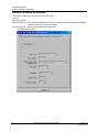
Modbus RTU Master - Advanced Setup
Modbus RTU Master - Advanced Setup
Overview
The Modbus RTU Master Advanced protocol provides enhanced data throughput for applications
where the HC900 is being used in conjunction with a “Modbus-to-fieldbus” gateway device. In
these applications the gateway acts as a Modbus slave to the HC900 controller. The Modbus data
is connected into the HC900 control strategy using the Modbus Read, Modbus Write, and Modbus
Slave function blocks.
In order to achieve the enhanced data throughput, the HC900 communicates with the gateway
using large packets of contiguous Modbus register addresses. This packetization technique allows
the HC900 to exchange data with the gateway at rates up to the analog cycle rate of the controller
(depending on the operating characteristics of the gateway device). The packet sizes can be
adjusted to match the specifications of the gateway slave device.
Differences from standard Modbus RTU
There are several important ways in which the Advanced protocol differs from the standard
Modbus RTU Master protocol:
1. Under the Advanced protocol the Modbus register data is written to the slave devices during
every Modbus Master scan cycle. This behavior is different than the standard Modbus RTU Master
protocol, where the data is written only when the slave block’s Enable pin is ON.
2. The Enable pins on the Modbus function blocks do not control when the register data is written
to the slave device. Instead, they control the value that is written to the block. For example, if a
Modbus function block has the value 10 on its Write pin and the Enable pin is ON, then a value of
10 is written to the slave device. If the Enable pin is changed to OFF, the HC900 controller will
continue to write a value of 10 to the slave device once every Modbus Master scan cycle. If the
value on the Write pin is changed to 100 while the Enable pin is OFF, the controller will continue to
write a value of 10 to the slave device. The next time the Enable pin is changed to ON, the
controller will write the value 100 to the slave device.
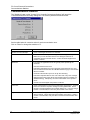
3. Modbus Register write operations are performed using Modbus Function Code 16 (Preset
Multiple Write). The number of registers written in a single transaction is based on the Advanced
Setup settings for the serial port.
140
HC900 Process Control Designer User Guide
Revision 15
September 2013