1
YAMAHA Electric Gripper
YRG Series
Userʼs Manual
EUT2127200
Ver. 2.00
E109
Introduction
Thank you for purchasing this electric gripper for YAMAHA robots.
This manual explains the safety precautions, handling, adjustment, inspection, and maintenance
work procedures in order to correctly and safely operate the electric gripper at its optimal operation
level. Please thoroughly read this manual before installing the electric gripper. After reading this
manual, store it in a safe place where all concerned personnel can refer to it immediately.
• This manual and electric gripper should be handled as a set.
• When the electric gripper is relocated, transferred, or sold, please explain a new manager or
owner to thoroughly read this manual.
• For electric gripper with specifications other than the standard specifications, if the explanation
is not particularly stated in this manual, please refer to the explanation of the standard
specifications.
• For details about actual operation of the electric gripper, please refer to the user’s manual for the
controller to be used.
• For details about YAMAHA robot or controller operations and cautions, please read the user’s
manual supplied with the robot or controller you are using and follow the instructions stated in
such manual.
Introduction
1
MEMO
2
Introduction
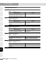
General contents
General contents
1.
Safety
1.1
1.2
1.3
1.4
Safety
Essential precautions
Operation
Warranty
2.
Overview of electric gripper
2.1
2.2
2.3
2.4
2.5
2.6
Features and functions
Product check
Part names and functions
Installation conditions
System configuration
Preparations for electric gripper use
3.
Installation and wiring
3.1
3.2
3.3
Installing the electric gripper
Installing the finger
Connection and wiring
3.3.1
3.3.2
3.3.3
3.3.4
3.3.5
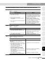
Verification and preparation
4.1
4.2
4.3
4.4
Verifying the robot controller settings
Verifying the gripper control board status
Status LEDs on the gripper control board
Weight parameters
Robot parameters
Axis parameters
5.
Operation
5.1
Turning the power on and off
5.1.1
5.1.2
5.1.3
5.2
5.3
5.3.1
5.3.2
5.3.3
5.4
1-1
1-2
1-4
1-6
2-1
2-1
2-2
2-3
2-4
2-5
2-6
3-1
3-1
3-4
3-6
Connecting to the controller (gripper control board)
Connecting the robot (for gripper) cable and relay cable
Connecting to the electric gripper main body
Wiring to the DC24V power supply
Wiring to the gripper emergency stop
4.
4.4.1
4.4.2
1-1
Turning the power on
Turning the power off
Power on timing chart
Manual movement
Return-to-origin
Return-to-origin operation
Overall return-to-origin
Gripper return-to-origin
Emergency stop
3-6
3-7
3-8
3-9
3-11
4-1
4-1
4-2
4-3
4-4
4-4
4-4
5-1
5-1
5-1
5-2
5-2
5-3
5-6
5-6
5-8
5-9
5-10
General contents
i
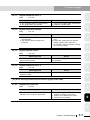
5.5
Status monitor
5-11
6.
Parameter settings
6-1
6.1
6.2
6.3
Parameter list
Axis parameter details
Other parameter details
7.
Gripper point data creation
7.1
7.2
7.3
7.4
Point
Point
Point
Point
8.
Robot language commands
8.1
8.2
Robot language command list
Robot language command details
8.2.1
data
data
data
data
input and editing
input by teaching
input by direct teaching
trace
Dedicated commands for gripper axis
GDRIVE
GDRIVEI
GHOLD
GHOLDI
GOPEN
GCLOSE
GORIGIN
GSTATUS
Other commands for gripper axis
ORIGIN
WHERE/WHERE2
WHRXY/WHRXY2
8.2.2
7-1
7-1
7-3
7-5
7-5
8-1
8-1
8-2
8-2
8-2
8-3
8-5
8-7
8-9
8-11
8-12
8-12
8-14
8-14
8-14
8-14
8.3
Operation chart of electric gripper
8-15
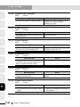
9.
Troubleshooting
9-1
9.1
Error messages
10. Periodic inspection and maintenance
10.1 Before beginning work
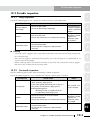
10.2 Periodic inspection
10.2.1
10.2.2
Daily inspection
Six-month inspection
9-1
10-1
10-1
10-3
10-3
10-3
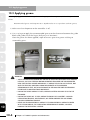
10.3 Applying grease
10-4
11. Specifications
11-1
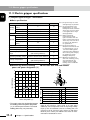
11.1 Electric gripper basic specifications
11.2 Gripper control board specifications
11.3 Electric gripper specifications
ii
6-1
6-3
6-8
General contents
11-1
11-1
11-2
1.1 Safety
1. Safety
1.1
1
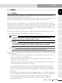
Safety
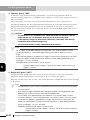
Before using this electric gripper, be sure to follow the safety precautions and instructions to
operate the electric gripper safely and correctly.
Also, bear in mind that not all safety items can be listed in detail, so that accurate judgment by the
operator or service personnel is essential for operating the robot and controller safely.
2
Furthermore, please carefully read the user’s manual for the robot and/or controller and strictly
observe the safety instructions and cautions. Negligence of necessary safety measures or improper
handling may cause not only fault or damage to the electric gripper, robot, and/or controller, but
also a serious accident including injury of work personnel (installation engineers, operators, and
adjustment and inspection engineers) or even death.
3
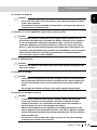
This manual classifies safety caution items and operating points into the following levels, along
with symbols for signal words "WARNING", "CAUTION" and "NOTE".
4
w
c
n
WARNING
"WARNING" indicates a potentially hazardous situation which, if not
avoided, could result in death or serious injury.
5
CAUTION
"CAUTION" indicates a potentially hazardous situation which, if not avoided, could
result in minor or moderate injury or damage to the equipment or software.
6
NOTE
Explains key points in the operation or helpful operation information.
Refer to the user's manual by any of the following methods to operate or adjust the electric gripper
safely and correctly.
7
1. Operate or adjust the electric gripper while referring to the printed version of the user's
manual (available for an additional fee).
2. Operate or adjust the electric gripper while viewing the CD-ROM version of the user's
manual on your computer screen.
3. Operate or adjust the electric gripper while referring to a printout of the necessary pages
from the CD-ROM version of the user's manual.
It is not possible to list all safety items in detail within the limited space of this
manual. So it is essential that the user have a full knowledge of basic safety rules
and also that the operator makes correct judgments on safety procedures during
operation.
For installation and operation of the electric gripper, please refer to the applicable
laws and regulations. Note that the warning labels and user’s manual are intended
for the Japanese market. If the electric gripper is exported outside Japan, it is
necessary to change warning labels and user’s manual to those suitable for a
destination country.
Chapter 1 Safety
1-1
8
9
10
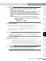
1.2 Essential precautions
1.2
1
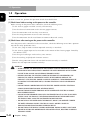
Essential precautions
Particularly important cautions for handling or operating the electric gripper are described below.
In addition, precautions during installation, operation, inspection, and maintenance are also
provided in each chapter. Be sure to comply with these instructions to ensure safe operation of the
electric gripper.
2
• The electric gripper is designed as components for general industrial machinery.
Only system designers or personnel who have enough knowledge or experience are allowed
to select a product model and handle it.
• The compatibility of the electric gripper with the customer’s system must be determined and
verified at the customer’s risk.
3
• When the electric gripper is incorporated into a system (machine unit or robot), it is
absolutely required that the system satisfies applicable laws and regulations related to the
safety precautions. Make sure that the system satisfies applicable laws and regulations, and
operate the electric gripper in a safe and correct manner in conformity with the laws and
regulations.
4
• The electric gripper is exempted from the application of the compact robot.
• Do not use the electric gripper for applications described below.
1. Medical units or devices with life-support system or their equivalents
5
2. Mechanisms or machine units for movement or transportation of personnel
3. Important safety components for machine units.
This product is not designed for applications that require a high level of safety.
6
7
(1) Use caution to prevent hands or fingers from being pinched or crushed.
• Strictly observe the caution to prevent hands or fingers from being pinched or crushed by
the movable parts when carrying or teaching the robot or electric gripper.
• Attach the Warning labels supplied with the electric gripper to legible locations near the
robot equipped with the electric gripper or the robot.
w
8
WARNING
MOVING PARTS CAN PINCH OR CRUSH.
Keep hands away from movable parts.
Warning label
9
10
1-2
Chapter 1 Safety
1.2 Essential precautions
(2) Cautions on disposal
c
1
CAUTION
• Do not throw this product into a fire. Doing so may cause the product to explode
or toxic gas to produce.
• If the product cannot be operated or if the product is no longer used, dispose of
it appropriately as industrial waste.
2
(3) Cautions on use for applications particularly requiring safety
c
CAUTION
If the customer studies to operate this electric gripper under conditions or in an
environment other than those not stated in the product catalog or user’s manual or
to use it for applications particularly requiring the safety, such as air craft facility,
combustion equipment, amusement machinery, inside of the clean room, safety
device, or other unit that improper operation may greatly affect other person’s life
or property, take appropriate safety measures into consideration, such as operation
with a sufficient allowance to the rating or performance, or failsafe measures. If
such case arises, always contact YAMAHA.
(4) Use of dedicated parts
c
6
CAUTION
• Protect this electric gripper from the direct sunlight or moisture content and take
dew condensation preventive measures, and then store the electric gripper in a
location with a height of 30 cm or more from the floor level inside a dark cold
place.
• Do not apply any vibration or impact to the electric gripper during storage.
7
(6) Cautions on workpiece removal
c
4
5
CAUTION
Be sure to use YAMAHA’s dedicated parts for the cables between the gripper main
body and controller.
(5) Cautions on storage
c
3
8
CAUTION
• To remove the workpiece with the power turned off, detach the finger and remove the workpiece since the double-cam type incorporates a speed reduction mechanism. If it is attempted to forcibly remove the workpiece or open the finger, this may cause damage to the gripper.
• Remove the workpiece from the gripper before stopping the operation of the
electric gripper for an extended period of time. If the electric gripper is stopped
with the workpiece kept held for an extended period of time, this may adversely
affect movable parts.
• The self-lock is not activated in the single-cam type. You can move the finger
manually even with the power turned off.
Chapter 1 Safety
9
10
1-3
1.3 Operation
1.3
1
Operation
After the installation, adjustment, inspection, maintenance, or repair work of the electric gripper
has been carried out, perform the operation checks described below.
(1) Check items before turning on the power to the controller
Before turning on the power to the controller, check the following items.
2
q Is the electric gripper installed securely and correctly?
w Are the electrical connections to the electric gripper correct?
e Are the connections with auxiliary units correct?
r Are the safety protection measures taken correctly?.
3
t Are the contentions for the installation environment observed strictly?
(2) Check items after turning on the power to the controller
After the power to the controller has been turned on, check the following items from a position
outside the safety protection fence.
4
q Is the start, stop, or mode selection operated correctly as intended?
w Is the electric gripper operated as intended? Is the motion of the electric gripper limited by
the software limit?
e Are the signal exchanges with auxiliary units correct?
5
r Are the teaching and playback functions correct?
t Do the safety protection fence and interlock function correctly as intended?
y Does the auto operation function correctly?
6
w
7
8
9
10
1-4
WARNING
• When starting the operation or adjustment after the gripper has been
installed in the system, strictly observe the safety measures of the system.
Failure to do so may cause serious personal injury.
•Before supplying the electric power to the product or operating the product, be sure to confirm the safety in the working area of the product. If the electric power is supplied carelessly, the operator may be
in contact with movable PARTS, causing electrical shock or personal
injury.
• Do not touch connectors with the electric power supplied. Electrical
shock or malfunction may otherwise result.
• Do not touch exposed terminals of the controller. Electrical shock
may otherwise result.
• Do not allow personnel who use a pacemaker to get access to an area
within 1 m of the product. The strong magnetism of the magnet inside
the product may cause the pacemaker to malfunction.
• Do not splash the water onto the product, wash it, or operate it under
the water. Personal injury, electrical shock, or fire caused by production malfunction may otherwise result.
• Do not touch the product during operation. Doing so may cause your
finger to be pinched or entangled into other device, resulting in serious
personal injury.
Chapter 1 Safety
1.3 Operation
• If a power failure occurs during operation, turn off the power. If not
turned off, the product may move suddenly after the electric power is
recovered. This may cause damage to the machine unit or serious personal injury.
•Before moving movable parts of the product manually for the direct
teaching, make sure that the servo is turned off. Serious personal injury
may otherwise result.
• If unusual heat, smoke, or odor is found in the product, turn off the
power immediately. Damage to the product or fire may otherwise result.
• If a fatal error occurs in the product, turn off the power immediately.
Personal injury, or damage or breakage of the machine unit caused by
production malfunction may otherwise result. After the power has been
turned off, do not turn it on again unless the cause of the error is located and removed completely.
• Turn on the power to the units from the host unit in order. If not, the
product may move suddenly, causing serious personal injury or damage to the machine unit.
• Do not put your finger or any object in the opening of the product.
Fire, electrical shock, or serious personal injury may otherwise result.
c
1
2
3
4
5
CAUTION
The motor is heated up and the product surface is hot during operation. Take
appropriate measures so that the heat does not adversely affect workpieces
around the product.
6
7
8
9
10
Chapter 1 Safety
1-5
1.4 Warranty
1.4
1
Warranty
For information on the warranty period and terms, please contact our distributor where you
purchased the product.
■ This warranty does not cover any failure caused by:
1.
Installation, wiring, connection to other control devices, operating methods, inspection or
maintenance that does not comply with industry standards or instructions specified in the
YAMAHA manual;
2.
Usage that exceeded the specifications or standard performance shown in the YAMAHA
manual;
3.
Product usage other than intended by YAMAHA;
4.
Storage, operating conditions and utilities that are outside the range specified in the manual;
5.
Damage due to improper shipping or shipping methods; 6.
Accident or collision damage;
4
7.
Installation of other than genuine YAMAHA parts and/or accessories; 8.
Modification to original parts or modifications not conforming to standard specifications
designated by YAMAHA, including customizing performed by YAMAHA in compliance with
distributor or customer requests;
5
9.
Pollution, salt damage, condensation;
2
3
6
10.
Fires or natural disasters such as earthquakes, tsunamis, lightning strikes, wind and flood
damage, etc;
11.Breakdown due to causes other than the above that are not the fault or responsibility of
YAMAHA;
■ The following cases are not covered under the warranty:
7
1.
Products whose serial number or production date (month & year) cannot be verified.
2.
Changes in software or internal data such as programs or points that were created or
changed by the customer.
3.
Products whose trouble cannot be reproduced or identified by YAMAHA.
4.
Products utilized, for example, in radiological equipment, biological test equipment
applications or for other purposes whose warranty repairs are judged as hazardous by
YAMAHA.
8
9
10
THE WARRANTY STATED HEREIN PROVIDED BY YAMAHA ONLY COVERS DEFECTS IN
PRODUCTS AND PARTS SOLD BY YAMAHA TO DISTRIBUTORS UNDER THIS AGREEMENT. ANY
AND ALL OTHER WARRANTIES OR LIABILITIES, EXPRESS OR IMPLIED, INCLUDING BUT NOT
LIMITED TO ANY IMPLIED WARRANTIES OF MERCHANTABILITY OR FITNESS FOR A PARTICULAR
PURPOSE ARE HEREBY EXPRESSLY DISCLAIMED BY YAMAHA. MOREOVER, YAMAHA SHALL
NOT BE HELD RESPONSIBLE FOR CONSEQUENT OR INDIRECT DAMAGES IN ANY MANNER
RELATING TO THE PRODUCT.
Ver.1.00_201205
1-6
Chapter 1 Safety
2.1 Features and functions
2. Over view of electric gripper
2.1
1
Features and functions
This YAMAHA electric gripper for robots is so designed that it achieves highly accurate holding
power, position, and speed controls through the closed loop control using the stepping motor
and rotary encoder. As a dedicated option board is assembled into the YAMAHA robot controller
RCX240 and the electric gripper is set as an auxiliary axis of the robot, the electric gripper can be
controlled easily.
Use of a special cam structure ensures lightweight and compact electric gripper main body even
with high holding power.
n Features
2
3
● Holding power control
The holding power of the gripper can be set to a desired level ranging from 30 to 100% (in
1% steps).
4
● Speed control
The movement speed (20 to 100%) or acceleration (1 to 100%) of the gripper can be set to a
desired level (in 1% steps).
5
● Multi-point position control
The positioning points of the gripper can be set freely.
6
● Easy parameter setup
Both the YAMAHA robot common parameters and the parameters specially designed for the
gripper can be used.
7
● Programming using robot language commands
Control programs for the electric gripper are easily created using YAMAHA robot language
commands.
8
9
10
Chapter 2 Overview of electric gripper
2-1
2.2 Product check
2.2
1
2
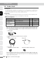
Product check
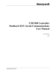
(1) Packing box
The robot controller is high precision equipment and is carefully packed in a cardboard box
to avoid shocks and vibrations. If a serious damage or dent is found on the package, please
contact your YAMAHA sales dealer without unpacking the box.
(2) Unpacking
Make sure that you do not drop the package or give any shock to it during unpacking. After
unpacking, carefully check the parts and components listed below.
3
■ Parts and components
Name
Electric gripper
1
w Option board
Gripper control board
1
Robot (for gripper) cable
1
Relay cable
1
(Note 2)
Connector for 24V power supply
1
(Note 3)
Connector for gripper emergency stop
1
(Note 4)
r Accessories
(Note
(Note
(Note
(Note
5
Remark
q Main body
e Cables
4
Q’ty
(Note 1)
1) This board has already been installed in the controller you have purchased.
2) This cable is intended to connect the electric gripper main body and robot (for gripper) cable.
3) This connector is intended to connect the gripper control board and DC24V power supply.
4) This connector is intended to connect the gripper control board and the emergency stop
circuit of the electric gripper.
q Electric gripper
6
w Gripper control board (incorporated into the controller)
7
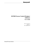
e Cable
• Robot (for gripper) cable
• Relay cable
r Accessories
• Connector for 24V power supply
• Connector for gripper emergency stop
8
9
10
Parts and components shown above are intended for one electric gripper set. Make sure
that the components you have received meet the contents of your order. The cable model
may vary depending on the cable length. For details, see "3.3.2 Connecting the robot (for
gripper) cable and relay cable".
2-2
Chapter 2 Overview of electric gripper
2.3 Part names and functions
2.3
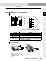
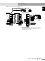
Part names and functions
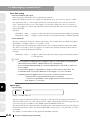
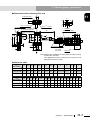
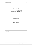
1
This section explains the part names and functions of the gripper control board.
The gripper control board is an option to be assembled into the controller and has already been
installed in an optimal slot of the controller before shipment.
n Part names and functions of gripper control board
2
Part names and functions
OP.1
MOTOR
OP.3
PWR
SRV
XM
RCX240
RPB
ERR
3
ROB
I/O
r
XY
YM
BATT
XY
SEL
q
ROB
I/O
4
ZR
OP.2
ZM
OP.4
STD.DIO
BATT
ZR
RGEN
w
ACIN
e
P
N
SAFETY
L
RM
N
L1
N1
EXT.E-STOP
PIN13−14
5
(Figure when viewed from the front of the controller)
Name
Function
q
ACT
Connector to be connected to the gripper main body.
w
POWER
Board drive power input connector.
e
GE-STOP+
GE-STOP–
Emergency stop input terminal.
r
Status LEDs
Four LEDs show the status of the gripper control board.
For details about LED indications, see "4.3 Status LEDs
on the gripper control board".
6
7
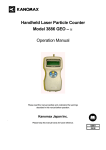
■ Electric gripper main body
Part names and functions
• Screw type
8
• 3-finger type
4
4
9
3
1
1
2
1.
2.
3.
4.
Finger installation tap hole
Guide block (open/close slider)
Finger positioning pin
Cable
2
3
10
Chapter 2 Overview of electric gripper
2-3
2.4 Installation conditions
2.4
1
Installation conditions
Be sure to strictly observe the following environmental conditions when installing the electric
gripper.
Items
2
Working temperature
0 to 40°C
Working humidity
35 to 90% RH (no condensation)
Altitude
0 to 1000 meters above sea level
Ambient environments
Avoid installing near water, cutting water, oil, dust,
metallic chips and organic solvent.
Avoid installation near corrosive gas and corrosive
materials.
Avoid installation in atmosphere containing inflammable
gas, dust and liquid.
Avoid installation near objects causing electromagnetic
interference, electrostatic discharge and radio frequency
interference.
Vibration
Do not subject to impacts or vibrations.
Working space
Allow sufficient space margin to perform jobs (teaching,
inspection, repair, etc.)
3
4
5
w
WARNING
Avoid installing the electric gripper in locations where the ambient
conditions may exceed the working temperature or humidity stated above,
or in environments where excessive moisture, corrosive gas, metallic
powder, or dust is produced. MALFUNCTIONS, FAILURES OR SHORT CIRCUITS MAY
OTHERWISE RESULT.
w
WARNING
• This electric gripper does not comply with the explosion-proof specifications.
• DO NOT USE THE ELECTRIC GRIPPER IN ENVIRONMENTS CONTAINING INFLAMMABLE
GAS, DUST OR LIQUIDS.
EXPLOSIONS OR FIRE COULD OTHERWISE RESULT.
w
WARNING
AVOID USING THE ELECTRIC GRIPPER IN LOCATIONS SUBJECT TO ELECTROMAGNETIC
INTERFERENCE, ELECTROSTATIC DISCHARGE OR RADIO FREQUENCY INTERFERENCE.
Malfunctions of the electric gripper may otherwise result.
w
WARNING
Do not use the electric gripper in locations subject to excessive vibration.
Gripper main body installation bolts may otherwise become loose, causing
the gripper to fall down.
6
7
8
9
Specifications
10
2-4
Chapter 2 Overview of electric gripper
2.5 System configuration
2.5
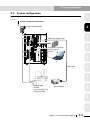
System configuration
1
Use of YAMAHA electric gripper makes it possible to construct a system configuration shown
below.
System configuration illustration
2
Programming box RPB
OP.1
MOTOR
OP.3
PWR
SRV
XM
RCX240
3
RPB
ERR
Robot (for gripper) cable
ROB
I/O
XY
YM
BATT
XY
SEL
COM
ROB
I/O
ZR
OP.2
ZM
STD.DIO
BATT
ZR
SAFETY
OP.4
RGEN
P
4
Drive power supply for
electric gripper
DC24V
N
ACIN
L
RM
5
N
L1
EXT.E-STOP
PIN13-14
N1
PC
6
Relay cable
7
YAMAHA robot
• SCARA
• Cartesian robot XY-X
• Single-axis robot
8
Electric gripper
9
10
Chapter 2 Overview of electric gripper
2-5
2.6 Preparations for electric gripper use
2.6
1
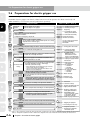
Preparations for electric gripper use
This section explains the basic preparation procedures until the robot is operated with the
YAMAHA electric gripper. For details about how to install or operate the robot main body and
robot controller, see relevant manuals published separately.
Basic procedure
Power ON
4
Install the gripper on the robot.
Install the finger on the gripper.
Install the controller.
• Make cable and connector connections.
• Ground the controller.
• Configure an emergency stop circuit.
11. Precautions for cable
routing and installation
This manual 3.3 Connection and wiring
Chapter 4 Parallel I/O interface
Chapter 5 SAFETY I/O interface
See the serial I/O instruction
manuals for detailed
information.
Verify that the wiring and power voltage are correct. Turn on the power and servo.
Chapter 1 3. Turning power on and off
Check that no alarm is issued after turning power on.
Chapter 3 12. Checking the robot
controller operation
Verify the gripper Verify that the gripper control board is installed in the
board.
controller and that it is set valid.
Initial setting
Set the following parameters to optimize the robot operation.
• Tip weight (workpiece weight + tool weight)
Parameter initial
• Soft limits (movement range)
* Before determining soft limit positions by jog movement,
setting
return-to-origin must first be complete.
* Set the "Axis tip weight" parameter if the robot is set to
"MULTI" or has an auxiliary axis.
* Always set this parameter when using the robot for the
first time. After that, change it as needed.
Absolute reset/ Perform the absolute reset or return-to-origin to teach the
return-to-origin origin position.
7
This manual 3.1 Installing the electric gripper
This manual 3.2 Installing the finger
Chapter 3 1. Unpacking
When a serial I/O board is added:
Set the station number, communication speed, etc. (Setup
depends on the serial I/O type.)
Check that the robot type setting in the controller matches
Robot type check the robot that is actually connected.
5
6
Install the
gripper.
~
3
Installation, connection and wiring
2
Refer to: (Note 1, Note 2)
* Always perform absolute reset when using the robot for
the first time. After that, reperform it only when the origin
position becomes indefinite (return-to-origin incomplete).
Chapter 7 1. "SYSTEM" mode
(Robot type can be
checked on the initial
screen in SYSTEM mode.)
This manual 4.1 Verifying the robot controller settings
This manual 4.2 Verifying the gripper control
board status
Chapter 7 2.3 Robot parameters
• Tip weight
Chapter 7 2.4 Axis parameters
• + Soft limit
• – Soft limit
• Axis tip weight
This manual 6.2 Axis parameter details
• + Soft limit
• – Soft limit
OP
Chapter 5 9. Return-to-origin
OP
Chapter 5 10.Absolute reset
This manual 5.3 Return-to-origin
Parameter setting Set parameters according to the operation conditions.
Chapter 7 2. Parameters
This manual 6. Parameter settings
Point data editing Create or edit point data according to the robot operation.
Chapter 5 3. Displaying and editing point data
This manual 7. Gripper point data creation
OP
Programming
Create programs according to the robot operation.
Check that the safety devices such as an emergency stop circuit function correctly.
Make a trial run using step operation and make adjustment as needed.
OP
Chapter 3 3. Stopping the program
13. Executing the next step
OP
2. Automatic operation
Chapter 3 7. Changing the automatic
movement speed
~
Start operation.
Chapter 5 4. Displaying, editing and
setting pallet definitions
OP
Chapter 4 1. "PROGRAM" mode
See the programming manual
for information about the
programming language.
This manual 8. Robot language commands
~
10
OP
* Programming is unnecessary if not using a program
such as in operation with I/O commands.
Trial operation Operation
9
Data setting
8
(Note 1) [OP] “Chapter XX” stated in the “Refer to” field shows a chapter No. in the operation manual for RCX240 controller you need to refer to.
(Note 2) “Chapter XX” stated in the “Refer to” field shows a chapter No. in the user’s manual for RCX240 controller you need to refer to.
2-6
Chapter 2 Overview of electric grippe
3.1 Installing the electric gripper
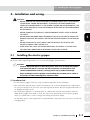
3. Installation and wiring
w
3.1
WARNING
•Before starting the installation or adjustment work, post a sign stating
"UNDER WORK. POWER ON PROHIBITED" to prevent the power from being TURNED on unintentionally. If the power is turned on unintentionally, this
may cause electrical shock or personal injury due to sudden movement
of the product.
•Before handling the product, wear appropriate safety gears to ensure
the safety.
• Do not bump or throw away the product package. Be sure to handle the
product package with great care so that excessive impact is not applied
to it.
• Do not stand or put heavy object on the product package so that excessive force is not applied to it.
•After unpacked, hold the gripper main body to handle it. Do not hold
the cable or connector to transport the electric gripper.
Installing the electric gripper
2
3
4
5
Follow the instructions below to secure the electric gripper to the installation plate.
For details about tap hole positions, see "11.3 Electric gripper specifications".
c
1
CAUTION
• Keep an adequate space for the maintenance work when installing the product.
If an adequate space is not kept, the daily inspection or maintenance work cannot be performed correctly, causing system stop or product breakage.
• When installing the electric gripper, avoid holding the movable part or cable of
the product. Product breakage may otherwise result.
6
7
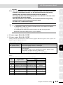
(1) Installation bolt
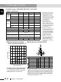
• Fix the electric gripper securely using installation tap holes at four locations.
• The installation tap hole part is made of aluminum. So, if the installation bolt is tightened at
an excessive torque level, this may cause the tap hole to break. Be sure to tighten the bolts at
an appropriate torque level.
• The installation tap hole is a through-hole. If a bolt to be screwed-in beyond the effective
depth of the gripper main body is used, this may cause damage to parts inside the gripper.
Never use a bolt with a screw-in length exceeding the effective depth.
On the other hand, if the length of the installation bolt is too short, this may cause insufficient
clamping force.
8
9
10
Chapter 3 Installation and wiring
3-1
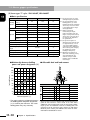
3.1 Installing the electric gripper
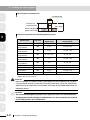
Max. length of installation bolt
1
Installation bolt
Thickness of
installation plate
2
Effective depth of
gripper main body
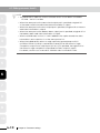
Effective length and recommended tightening torque
3
Tap hole
Effective
depth (mm)
Recommended tightening
torque (N•m)
YRG-2005SS
M3
3
0.56 to 0.69
YRG-2010S
YRG-2005W
M3
6 (5)
0.56 to 0.69
YRG-2815S
YRG-2810W
M4
8 (6)
1.35 to 1.65
YRG-4225S
YRG-4220W
M5
8, 10, (7.5)
2.7 to 3.3
YRG-2020FS
YRG-2020FT
M4
6
1.35 to 1.65
YRG-2840FS
YRG-2840FT
M5
7.5
2.7 to 3.3
YRG-2004T
M3
3
0.56 to 0.69
YRG-2013T
M3
6 (5)
0.56 to 0.69
YRG-2820T
M4
8 (6)
1.35 to 1.65
YRG-4230T
M5
8 (7.5)
2.7 to 3.3
Model name
4
5
6
7
Max. length
A numeric value stated in ( ) shows the effective depth for installation of the electric
gripper on the top surface.
w
WARNING
Strictly observe the above instructions about installation bolt to securely
fix the gripper. Failure to follow the instructions may cause the gripper or
workpiece to be loose or fallen down, resulting in equipment breakage or
personal injury.
c
CAUTION
The recommended tightening torque shows a general value. You should determine
an appropriate level by taking the installation bolt you are using and/or the material
of the seating surface into consideration.
8
9
10
3-2
Chapter 3 Installation and wiring
3.1 Installing the electric gripper
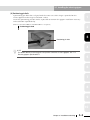
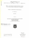
(2) Positioning pin hole
A positioning pin hole that is aligned with the center axis of the finger is provided on the
surface opposite to the finger installation surface.
Use of this positioning pin hole makes it possible to maintain the gripper installation accuracy
and installation reproducibility.
1
(However, the YRG-2005SS and YRG-2004T is excepted.)
2
Positioning pin hole
3
Positioning pin hole
4
n
NOTE
For details about positioning pin hole position and size of each gripper, see "11.3
Electric gripper specifications".
5
6
7
8
9
10
Chapter 3 Installation and wiring
3-3
3.2 Installing the finger
3.2
1
2
Installing the finger
Tap holes have been made in the guide block of each electric gripper to install a tool, such as
finger. Follow the instructions below to install a tool, such as finger on the electric gripper.
For details about tap hole positions, see "11.3 Electric gripper specifications".
(1) Installation bolt
• When installing the finger, tighten the bolt while holding the finger firmly so that any
excessive force or shock is not applied to the guide block.
• The installation tap hole in the guide block is a through-hole. If a bolt to be screwed-in
beyond the effective depth of the guide block is used, this may cause the gripper to malfunction or break. Never use a bolt with a screw-in length exceeding the effective depth.
On the other hand, if the length of the installation bolt is too short, this may cause insufficient
clamping force.
3
Finger installation bolt
4
Gripper main body
Gripper main body
Guide rail
5
Effective depth
Finger installation
part
Installation
bolt
6
Guide block
Positioning pin
Finger
Tap hole and effective depth
7
Tap hole
Effective
depth (mm)
YRG-2005SS
M2
3.5
YRG-2010S
YRG-2005W
M3
5
YRG-2815S
YRG-2810W
M4
5
YRG-4225S
YRG-4220W
M5
8
YRG-2020FS
YRG-2020FT
M3
5
YRG-2840FS
YRG-2840FT
M4
7.5
YRG-2004T
M2
4
YRG-2013T
M3
8
YRG-2820T
M3
6
YRG-4230T
M4
8
Model name
8
9
10
3-4
Chapter 3 Installation and wiring
3.2 Installing the finger
w
WARNING
Strictly observe the above instructions about installation bolt to securely
fix a tool, such as finger. Failure to follow the instructions may cause the
finger or workpiece to be loose or fallen down, resulting in equipment
breakage or personal injury.
c
CAUTION
When installing the finger, tighten the installation bolt at a tightening torque level
suitable for the finger material.
1
2
3
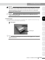
(2) Positioning pin
Use of positioning pins provided on the guide block makes it possible to maintain the finger
installation accuracy and installation reproducibility.
Positioning pin
4
5
Positioning pin
6
n
NOTE
For details about positioning pin position and size of each gripper, see "11.3 Electric
gripper specifications".
7
8
9
10
Chapter 3 Installation and wiring
3-5
3.3 Connection and wiring
3.3
1
Connection and wiring
This section explains the cable connection and wiring necessary to operate and control the electric
gripper.
w
WARNING
•An appropriate safety circuit or device should be so designed that system breakage or personal injury does not occur if the product stops in case of a system trouble, such as an emergency stop or a power failure.
• Perform the product wiring while referring to the wiring procedures
stated in the user’s manual to connect all cables correctly. Connect
the cables and connectors securely so that any cable or connector is
not loose or disconnected. Product malfunction or fire may otherwise
result.
c
CAUTION
Before connecting the cables, make sure that the controller and electric gripper are
powered off completely. If the cable is connected or disconnected with the power
turned on, this may cause the electric gripper to break.
2
3
4
5
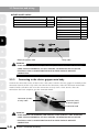
3.3.1
6
Connect the 10-pin connector (female) of the robot (for gripper) cable supplied with the electric
gripper to the 10-pin connector (male) of the gripper control board installed in the controller. To
connect the connector, make the connector orientations matched with each other and insert the
connector securely until a click sounds.
Connecting to the controller (gripper control board)
7
Connector (male)
of controller
8
9
10
3-6
Chapter 3 Installation and wiring
Connector (female)
of connection cable
3.3 Connection and wiring
● List of controller connector signals
Terminal No.
Symbol
Function
A1
EA
Encoder signal input A-phase
A2
EZ
Encoder signal input Z-phase
A3
0V
Encoder 0V power output
A4
BN
Motor output B-phase
A5
B
Motor output B-phase
B1
EB
Encoder signal input B-phase
B2
+5V
Encoder +5V power output
B3
SLD
Shielding line
B4
A
Motor output A-phase
B5
AN
Motor output A-phase
1
A1
B1
2
A5
B5
w
WARNING
Avoid damage to the robot (for gripper) cable or relay cable. Damaged
cable, excessive bending, pulling, winding, or wedging may cause fire,
electrical shock, or malfunction due to earth leakage or faulty
conducting.
c
CAUTION
The accessory connection cable consists of two harnesses that separate the
encoder lines from the motor lines. To connect the electric gripper to the controller,
this connection cable should be used.
This cable has excellent flexibility. However, do not store the cable in a movable
wiring duct (cable guide, etc.) with a radius of 66 mm or less.
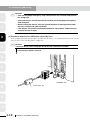
3.3.2
3
Connector for gripper connection
(Controller side)
4
5
6
Connecting the robot (for gripper) cable and relay cable
Connect the robot (for gripper) cable and relay cable.
As shown in the table below, the cable model number may vary depending on the cable length.
Each cable consists of two harnesses that separate the encoder lines from the motor lines. To
connect the connector, make the connector orientations matched with each other and insert the
connector securely until a click sounds.
c
7
8
CAUTION
Be sure to adjust the total length of the robot (for gripper) cable and relay cable to
14m or less. If the total length exceeds this level, this may cause malfunction due to
noise.
9
10
Chapter 3 Installation and wiring
3-7
3.3 Connection and wiring
● Cable model number
1
Robot (for gripper) cable model number Length
Relay cable model number Length
KCF-M4751-3
3.5m
KCF-M4811-1
0.5m
KCF-M4751-5
5m
KCF-M4811-2
1m
KCF-M4751-A
10m
KCF-M4811-3
1.5m
KCF-M4811-4
2m
KCF-M4811-5
2.5m
KCF-M4811-6
3m
KCF-M4811-7
3.5m
KCF-M4811-8
4m
2
3
4
Robot (for gripper) cable
5
w
6
3.3.3
7
Relay cable
WARNING
Avoid damage to the robot (for gripper) cable or relay cable. Damaged
cable, excessive bending, pulling, winding, or wedging may cause fire,
electrical shock, or malfunction due to earth leakage or faulty
conducting.
Connecting to the electric gripper main body
Connect the connector (male) of the harness that comes from the electric gripper main body to the
connector (female) of the relay cable. To connect the connector, make the connector orientations
matched with each other and insert the connector securely until a click sounds. After the
connection has been complete, put the connector hood.
8
Connector (female)
of relay cable
Connector (male)
of electric gripper
Connector hood
9
w
10
WARNING
Avoid damage to the robot (for gripper) cable or relay cable. Damaged
cable, excessive bending, pulling, winding, or wedging may cause fire,
electrical shock, or malfunction due to earth leakage or faulty
conducting.
3-8
Chapter 3 Installation and wiring
3.3 Connection and wiring
3.3.4
Wiring to the DC24V power supply
1
The following shows the terminal layout of the power connector on the
controller side (gripper control board).
● Power connector
1
Terminal No.
Connection
Function
1
+24V
Motor power supply, control
power supply
2
0V
Power supply 0V
3
FG
Frame ground (terminal for
D-grade grounding work)
c
2
2
3
Power connector
(Controller side)
3
CAUTION
Do not connect the terminals incorrectly. Doing so may cause a malfunction.
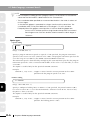
(1) Wiring to the power connector
Prepare electric wires to be connected to the DC24V power supply and connect the wires to
the power connector supplied with the electric gripper.
● Length of exposed wire lead
5
Strip the wire to expose 7 mm of bare lead.
7mm
AWG size
4
: 28 to 16
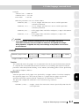
● Wiring
Follow the steps below to insert the wire lead into the opening in the power connector and
make sure that the electric wire is not disconnected.
6
7
q Loosen the screw on the
top with a small flat-blade
screwdriver.
w Insert the wire lead
stripped into the electric
wire insertion port
correctly until it is in
contact with the far side.
8
e Loosen the screw on the
top with a flat-blade
screwdriver. Lightly pull
the electric wire to make
sure that it is not disconnected.
9
Tighten the screw on the top of the power connector with tightening torque shown below.
Tightening torque: 0.22 to 0.25N•m
w
WARNING
Connect the grounding line to the frame ground terminal securely to
prevent malfunction caused by noise.
Chapter 3 Installation and wiring
10
3-9
3.3 Connection and wiring
1
c
2
3
4
CAUTION
• Take out the gripper emergency stop connector from the controller and perform
the wiring work.
• Insert one electric wire into one electric insertion port of the gripper emergency
stop connector.
• When inserting the electric wire, pay special attention so that frayed wire leads
are not in contact with other conductor.
• If the electric wire insertion portion deteriorates for some reason, strip the electric
wire and connect it again.
(2) Preventive measures for malfunction caused by noise
If the gripper operation may become unstable due to noise, it is recommended to insert a ferrite
core or noise filter into the power supply line.
c
CAUTION
Locate the ferrite core or noise filter as close to the controller as possible.
Connecting the power connector
5
6
7
Controller side
Ferrite core, etc.
8
9
10
3-10
Chapter 3 Installation and wiring
3.3 Connection and wiring
3.3.5
Wiring to the gripper emergency stop
An emergency stop input dedicated to the electric gripper is provided on the gripper control board.
The customer performs the wiring to this emergency stop input as needed.
w
WARNING
•An external emergency stop circuit must be constructed so that the
drive power can be shut down immediately in case of an emergency stop. Install an emergency stop device in a place where all concerned
personnel can activate it if any danger occurs during operation. Personal injury may otherwise result.
• Do not construct a control so that the workpiece drops if a power
failure occurs. Construct a control that prevents workpiece drop if a
power failure occurs in the machine unit or if the emergency stop is
activated. Personal injury may otherwise result.
The following describes the terminal pin assignments of the gripper emergency stop connector on
the controller side (gripper control board).
1
2
3
4
● Connector for gripper emergency stop
Terminal No.
Symbol
Function
1
GE-STOP+
Gripper emergency stop input 1
2
GE-STOP-
Gripper emergency stop input 2
1
2
5
Connector for gripper emergency stop
(Controller side)
Gripper control board
+24V
POWER
DC24V
6
Electric gripper
1
2
Driver circuit
3
+24V_GND
7
Robot (for gripper)
cable
FG
Gripper emergency stop
+24V
GE-STOP+
1
GE-STOP-
2
8
+24V_GND
NC contact status of gripper emergency stop
Electric gripper status
NC contact of the gripper emergency stop
is closed (terminal numbers 1 and 2 are
short-circuited).
Gripper is put in the emergency stop cancel
status.
NC contact of the gripper emergency stop
is open (terminal numbers 1 and 2 are
open).
Gripper is put in the emergency stop status,
the servo of the electric gripper is turned off,
and the power to the gripper is shut down.
Chapter 3 Installation and wiring
3-11
9
10
3.3 Connection and wiring
1
2
c
CAUTION
• The gripper emergency stop is not interlocked with the emergency stop of the
controller.
• The servo status of the gripper axis can be set using "Gripper servo when E.stop"
of other parameters. (For details, see "6.3 Other parameter details".)
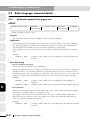
(1) Wiring to the gripper emergency stop connector
Prepare electric wires to be connected to the emergency stop circuit of the electric gripper and
connect the wires to the gripper emergency stop connector supplied with the electric gripper.
3
4
● Length of exposed wire lead
Strip the wire to expose 8 mm of bare lead.
8mm
AWG size
: 26 to 20
● Wiring
Follow the steps below to insert the wire lead into the opening in the gripper emergency stop
connector and make sure that the electric wire is not disconnected.
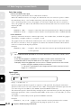
5
Insert the wire lead
while pushing down
the orange portion.
6
q While pushing down the orange portion,
insert the correctly stripped wire lead until
it is in contact with the electric wire insertion port.
7
8
c
9
CAUTION
• Take out the gripper emergency stop connector from the controller and perform
the wiring work.
• Insert one electric wire into one electric insertion port of the gripper emergency
stop connector.
• When inserting the electric wire, pay special attention so that frayed wire leads
are not in contact with other conductor.
• If the electric wire insertion portion deteriorates for some reason, strip the electric
wire and connect it again.
10
3-12
w When you stop pushing down the orange
portion, the wire lead is then connected.
For confirmation, lightly pull the wire lead.
(At this time, do not pull the wire lead
excessively.)
Chapter 3 Installation and wiring
3.3 Connection and wiring
(2) Interlocking with the RCX240 controller
The servo status of the gripper axis when the emergency stop button on the controller is pressed
can be set using the "Gripper servo when E.stop" parameter of other parameters. (For details,
see "6.3 Other parameter details".)
If the power to the controller and electric gripper is interlocking shut down with the emergency
stop, the customer takes safety measures suitable for the customer’s system while referring to
the circuit examples shown below.
w
WARNING
• Do not configure the control that allows the workpiece to drop when
stopped. Take appropriate workpiece drop prevention measures when a
power failure occurs in the machine unit or the emergency stop is activated.
• Thoroughly read this user’s manual, user’s manual for RCX240 controller, and user’s manual for robot with great care to take appropriate safety measures suitable for the customer’s system.
Circuit example 1) Gripper emergency stop is not interlocked with the controller
emergency stop and external emergency stop.
1
2
3
4
Controller
Electric gripper
Robot (for gripper)
cable
DC24V
Gripper
POWER
YRG+24V
1
2
3
Gripper emergency stop
FG
GE-STOP+
GE-STOP-
5
Gripper control board
ACT
6
DRIVER circuit
YRG+24V_GND
YRG+24V
1
2
7
YRG+24V_GND
RPB
Emergency stop
RPB
13
14
8
External emergency stop
SAFETY
3
4
13
14
E-STOPIN1
E-STOPIN2
E-STOP24V
E-STOPRDY
Internal +24V
9
E-STOP status
+24V_GND
GND
10
Chapter 3 Installation and wiring
3-13
3.3 Connection and wiring
Circuit example 2) Gripper emergency stop is not interlocked with the controller
emergency stop, but is interlocked with the external emergency stop.
1
Controller
Electric gripper
Robot (for gripper)
cable
2
Gripper
POWER
DC24V
Gripper control board
ACT
YRG+24V
1
2
3
FG
GE-STOP+
GE-STOP-
3
DRIVER circuit
YRG+24V_GND
YRG+24V
External emergency stop
1
2
YRG+24V_GND
RPB
Emergency stop
RPB
4
SAFETY
5
13
14
3
4
13
14
E-STOPIN1
E-STOPIN2
E-STOP24V
E-STOPRDY
Internal +24V
E-STOP status
+24V_GND
GND
Circuit example 3) Gripper emergency stop is interlocked with the controller
emergency stop and external emergency stop.
6
Controller
Electric gripper
7
Robot (for gripper)
cable
Gripper
POWER
DC24V
Gripper control board
ACT
YRG+24V
1
2
3
FG
8
DRIVER circuit
YRG+24V_GND
YRG+24V
GE-STOP+
GE-STOP-
1
2
YRG+24V_GND
RPB
Emergency stop
RPB
9
13
14
External +24V
External emergency stop
10
SAFETY
3
4
13
14
E-STOPIN1
E-STOPIN2
E-STOP24V
E-STOPRDY
Internal +24V
E-STOP status
+24V_GND
3-14
External +24V GND
Chapter 3 Installation and wiring
GND
4.1 Verifying the robot controller settings
4. Verification and preparation
4.1
1
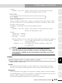
Verifying the robot controller settings
From the RPB programming box (hereafter referred to as "RPB"), you can verify whether or not the
gripper control board is installed in the robot controller. To verify the gripper control board, follow
the steps below.
2
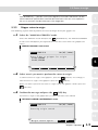
1 Select the "SYSTEM" mode.
2 Verify that the board name is indicated at the "Opt-i/f" item.
3
The gripper control board is installed if "Gripper 1" is indicated at the "Opt-i/f" item.
Example of "SYSTEM" mode screen
SYSTEM
V10.02
4
Robot
= YK250X
Axes
= XYZR+A
Standard= SRAM/364kB,DIO_N
Opt−i/f =
Gripper1,
PARAM
CMU
OPTION
INIT
5
DIAGNOS
TIP
When two gripper control boards are installed, "Gripper 1" and "Gripper 2" are
indicated. In a screen example shown above, one gripper is set as an auxiliary axis
of the scalar robot YK250X.
6
7
8
9
10
Chapter 4 Verification and preparation
4-1
4.2 Verifying the gripper control board status
4.2
1
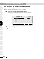
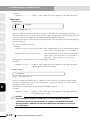
Verifying the gripper control board status
To operate the electric gripper, it is absolutely necessary that the gripper control board is ready for
operation. Verify the gripper control board status with the RPB.
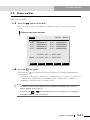
1 Select the "SYSTEM>PARAM>OP.BRD" mode.
The list of option boards installed in the robot controller is indicated.
2
"SYSTEM>PARAM>OP. BRD" mode
SYSTEM>PARAM>OP.BRD
3
1.Gripper1
2. −−−
3. −−−
4. −−−
4
5
V10.02
VALID
SELECT
2 Verify that "Gripper 1" is set at "VALID".
TIP
When two gripper control boards are installed, verify the settings of "Gripper 1" and
"Gripper 2".
6
7
8
9
10
4-2
Chapter 4 Verification and preparation
4.3 Status LEDs on the gripper control board
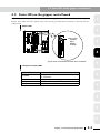
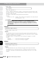
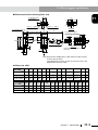
4.3
Status LEDs on the gripper control board
Four status LEDs are provided at the location on the gripper control board as shown in the figure
below. These LEDs show the board status. The meaning of each LED indication is described in the
table below.
1
Status LEDs
OP.1
MOTOR
OP.3
PWR
SRV
2
RCX240
RPB
ERR
XM
ROB
I/O
Status LEDs
POWER
RUN
READY
ALARM
XY
YM
BATT
XY
SEL
ROB
I/O
3
ZR
OP.2
ZM
BATT
ZR
OP.4
RGEN
STD.DIO
4
P
N
SAFETY
ACIN
L
RM
N
L1
N1
EXT.E-STOP
PIN13−14
(Figure when viewed from the front of the controller)
5
Functions of status LEDs
LEDs
Function
POWER
Lit (green) when the motor drive power (24V)
is turned on.
RUN
Lit (green) when the gripper is in operation.
READY
Lit (yellow) during correct operation.
ALARM
Lit (red) if an alarm occurs.
6
7
8
9
10
Chapter 4 Verification and preparation
4-3
4.4 Weight parameters
1
2
4.4
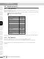
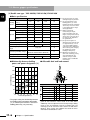
Weight parameters
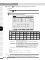
4.4.1
Robot parameters
The tip weight (workpiece weight + tool weight) of the robot is set for the "Tip weight [kg]/
WEIGHT" parameter in "kg" units.
At this time, the weight of the electric gripper (see the table below) is also added to the tool weight.
Weight of electric gripper main unit
Electric gripper model
3
4
5
6
Weight
YRG-2005SS
90g
YRG-2010S
160g
YRG-2815S
300g
YRG-4225S
580g
YRG-2005W
200g
YRG-2810W
350g
YRG-4220W
800g
YRG-2020FS
420g
YRG-2840FS
880g
YRG-2020FT
420g
YRG-2840FT
890g
YRG-2004T
90g
YRG-2013T
190g
YRG-2820T
340g
YRG-4230T
640g
For details about "Tip weight [kg]/WEIGHT" parameter, see the user’s manual for robot controller.
7
4.4.2
Axis parameters
The electric gripper does not use the "Axis tip weight [kg]/AXSTIP" parameter.
So, even when this parameter is changed, the acceleration does not change automatically.
8
For details about "Axis tip weight [kg]/AXSTIP" parameter, see the user’s manual for robot
controller.
9
10
4-4
Chapter 4 Verification and preparation
5.1 Turning the power on and off
5. Operation
5.1
1
Turning the power on and off
This section explains how to turn on and off the power, assuming that the electric gripper has been
connected completely according to the instructions stated in "3. Installation and wiring" and the
controller operates correctly.
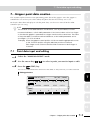
5.1.1
2
Turning the power on
1 Connect the RPB programming box to the controller.
Connect the RPB connector to the RPB connector terminal (RPB) on the front panel of
the controller.
3
2 Supply the power from the DC 24V power connector.
The "POWER" LED on the gripper control board lights up. (For details, see "4.3 Status LEDs
on the gripper control board".)
4
3 Supply the main power (power for motor drive) and control power from
the power terminal on the front panel of the controller.
The "PWR" LED lights up and the "MANUAL" mode screen will appear. (After the "PWR"
LED has been lit, it takes a maximum of 5 sec. per gripper for the controller to operate
normally. So, when two grippers are used, it takes a maximum of 10 sec.)
n
NOTE
• If the error message "Parameter destroyed" or "Memory destroyed" appears on
the screen when the power is turned on, be sure to initialize the parameters and
memory in the "SYSTEM" mode before performing the absolute reset or return-to origin. For details, see the user’s manual for YAMAHA robot controller RCX240.
• If the error message "10.21: Sys. backup battery low voltage" appears when the
power is turned on, replace the lithium battery (service life is about 4 years) in
the controller.
• After the robot controller has been turned off, wait at least 5 sec. before turning
the power on again. If the power is turned on again too quickly after it has been
turned off, the controller may not start up correctly.
6
7
8
4 Turn on the servo.
When the SAFE mode setting or serial I/O setting is enabled, the controller always starts
with the robot servo turned off. So, be sure to turn on the servo.
For details about how to turn on the servo, see the user’s manual for YAMAHA robot
controller RCX240.
n
5
NOTE
• If the "Servo on when power on" parameter is set at "NO", the controller always
starts with the robot servo turned off when power is turned on, regardless of SAFE
mode and serial I/O settings. For details, see the user’s manual for YAMAHA robot
controller RCX240.
• It takes a maximum of 5 sec. per gripper to complete the gripper servo on. So,
when two grippers are used, it takes a maximum of 10 sec.
Chapter 5 Operation
5-1
9
10
5.1 Turning the power on and off
5.1.2
1
Turning the power off
1 Turn off the main power (power for motor drive) and control power of
the controller.
2
2 Turn off the DC 24V power.
n
3
5.1.3
NOTE
Do not turn the power off while the program is running. Doing so may cause internal
system data conflict to occur. In this case, when the power is turned on again, the
program may not restart correctly.
Before turning the power off, be sure to exit or stop the program.
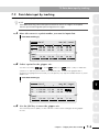
Power on timing chart
4
*1
on
Controller control power
5
Controller main power
(Power for motor drive)
6
DC 24V power
off
on
off
on
off
*1 Be sure to turn on the DC 24V power at the same time or before the controller control power
and main power are turned on.
It is recommended to turn on the controller control power and main power 100 ms or longer
after the DC 24V power has been turned on.
7
8
9
10
5-2
Chapter 5 Operation
5.2 Manual movement
5.2
Manual movement
The robot can be operated with the JOG (manual movement) key. In a similar manner to the robot
axis, the electric gripper can also be operated with the JOG (manual movement) key.
The manual movement with the JOG (manual movement) key is described as follows.
w
n
WARNING
Pressing the JOG key will move the robot. To prevent hazards, do not enter
the robot operation area.
NOTE
• The electric gripper cannot be moved unless the return-to-origin has been
completed. Before starting the manual movement, be sure to perform the return-to-origin.
• The movement speed is always 20% when the electric gripper is manually moved
continuously, regardless of the RPB speed display. (The maximum movement
speed in the "MANUAL" mode is 20% of the movement speed in the "AUTO"
mode and the minimum speed of the electric gripper is 20% of the maximum
speed.)
• When two robots are set, check the group selection display and perform the
manual movement. If the target group is different, press the ROBOT (LOWER +
MODE) key to change the target group.
• For details about software limit, see "6.2 Axis parameter details".
• If the current position is displayed in "pulse" units, you can move the servo on
axis manually even when the servo on and off axes are mixed.
• If the current position is displayed in "mm" units, you can move the axis only
when the servo on is set for all axes.
1
2
3
4
5
6
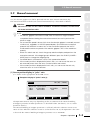
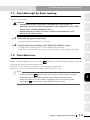
(1) Current position display in "pulse" units
"J" is shown in the right portion of the RPB screen.
7
Example of display in "pulse" units (J)
MANUAL
50%[MG][S0H0J]
Machine reference
*M1=
21593*M2=
*M4=
9875*m5=
POINT
PALLET
8216*M3=
728
VEL+
8
68468
9
VEL−
The operation contents may vary depending on the set contents of the "Manual Holding
of Gripper" parameter of other parameters as described below. (For details, see "6.3 Other
parameter details".)
The "Manual Holding of Gripper" parameter is valid only when the software version is Ver.
10.19 or later. When the software version is earlier than Ver. 10.19, the operation is the same
as that with the "Manual Holding of Gripper" parameter set at "INVALID".
Chapter 5 Operation
5-3
10
5.2 Manual movement
1. "Manual Holding of Gripper" parameter is set at "INVALID".
The holding operation of the manual movement becomes invalid.
In the same manner as the robot axis operation, the manual movement is as follows.
Pressing the JOG key will perform the inching operation of the axis corresponding to
the key (constant amount movement every time the key is pressed). Holding down
the key will continuously move the axis to the software limit position as a target.
When the JOG key is released or when the axis reaches the software limit, the axis
movement will stop.
The movement distance with the inching operation is the number of pulses that
equals the numeric value of the manual movement speed.
1
2
Example) When the manual movement speed is 20%,
the inching distance in "pulse" units is 20 pulses.
3
When you press the JOG key to move each axis to a position over ± software limit of
each axis, the message "2.1: Software limit over" appears and the axis cannot be
moved.
2. "Manual Holding of Gripper" parameter is set at "VALID".
4
The manual movement operation changes to the holding movement.
In this setting, the electric gripper can hold a workpiece.
Pressing the JOG key will perform the inching operation of the axis corresponding to
the key (constant amount movement every time the key is pressed).
Subsequently, holding down the key will continuously move the axis to the software
limit position as a target. When the JOG key is released or when the axis reaches the
software limit, the axis movement will stop.
As the manual movement is changed to the holding movement, the movement
distance with the inching operation is the number of pulses that equals "numeric
value of the manual movement speed + limit width pulse conversion value".
Additionally, the inching distance may not be constant due to the conversion
accuracy inside the gripper IF board.
5
6
Example) When the manual movement speed is 100%, the electric gripper model
is YRG-2815S, and the limit width is 2.00 mm (189 pulses),
the inching distance in "pulse" units = 100 + 189 pulses = 289 pulses.
7
8
When you press the JOG key to move each axis to a position over ± software limit of
each axis, the message "2.1: Software limit over" appears and the axis cannot be
moved.
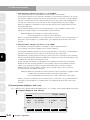
(2) Current position display in "mm" units
"X" is shown in the right portion of the RPB screen. "T" is shown in the "Tool coordinate" mode.
Example of display in "mm" units (X)
MANUAL
9
50%[MG][S0H0X]
Machine reference
*Mx=
151.05*My=
*Mr=
32.51 ma=
10
POINT
5-4
Chapter 5 Operation
PALLET
−3.27*Mz=
5.03
VEL+
49.23
VEL−
5.2 Manual movement
Example of display in "mm" units ("Tool coordinate" mode: T)
MANUAL
Machine reference
*Mx=
151.05*My=
*Mr=
32.51 ma=
POINT
1
50%[MG][S0H0T]
PALLET
−3.27*Mz=
5.03
VEL+
49.23
2
VEL−
3
The operation contents may vary depending on the set contents of the "Manual
Holding of Gripper" parameter of other parameters as described below. (For details,
see "6.3 Other parameter details".)
The "Manual Holding of Gripper" parameter is valid only when the software version is
Ver. 10.19 or later.
When the software version is earlier than Ver. 10.19, the operation is the same as that
with the "Manual Holding of Gripper" parameter set at "INVALID".
4
1. "Manual Holding of Gripper" parameter is set at "INVALID".
The holding operation of the manual movement becomes invalid.
In the same manner as the robot axis operation, the manual movement is as follows.
When the JOG key is pressed, the inching operation (constant amount movement
every time the key is pressed) is performed first.
Subsequently, holding down the key will perform the continuous movement. When
the JOG key is released or when the axis reaches the software limit, the axis
movement will stop.
The movement distance with the inching operation is "manual movement speed (%)
x 0.01 mm".
The inching distance may not be constant due to the conversion accuracy inside
the gripper IF board.
5
6
7
Example) When the manual movement speed is 20%,
the inching distance in "mm" units is 0.20 mm.
When you press the JOG key to move each axis to a position over ± software limit of
each axis, the message "2.1: Software limit over" appears and the axis cannot be
moved.
2. "Manual Holding of Gripper" parameter is set at "VALID".
8
The manual movement operation changes to the holding movement.
In this setting, the electric gripper can hold a workpiece.
Pressing the JOG key will perform the inching operation of the axis corresponding to
the key (constant amount movement every time the key is pressed).
Subsequently, holding down the key will continuously move the axis to the software
limit position as a target. When the JOG key is released or when the axis reaches the
software limit, the axis movement will stop.
As the manual movement is changed to the holding movement, the movement
distance with the inching operation becomes "manual movement speed (%) x 0.01 +
limit width) mm".
Additionally, the inching distance may not be constant due to the conversion
accuracy inside the gripper IF board.
Chapter 5 Operation
5-5
9
10
5.3 Return-to-origin
Example) When the manual movement speed is 20% and the limit width is 2.00 mm,
the inching distance in "mm" units = 0.20 + 2.00 mm = 2.20 mm.
1
2
When you press the JOG key to move each axis to a position over ± software limit of
each axis, the message "2.1: Software limit over" appears and the axis cannot be
moved.
5.3
Return-to-origin
3
Before starting the operation of the robot by turning on the power, it is necessary to perform
the return-to-origin. The return-to-origin operation adjusts the position of each robot axis to its
mechanical origin position to reset the position data in the controller.
The return-to-origin needs to be performed for the axes with the incremental specifications. Since
the gripper axis has the incremental specifications, perform the return-to-origin in either way
described in "5.3.2 Overall return-to-origin" or "5.3.3 Gripper return-to-origin".
4
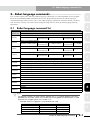
The parameters related to the return-to-origin are described below. For details about each
parameter, see "6. Parameter settings" and each parameter item described in the user’s manual for
robot controller.
Category
5
Parameter name
Origin sequence
Sets the order of return-to-origin axes.
(For details, see the user’s manual for robot
controller.)
Origin speed [%]
(for Gripper)
Sets the speed of the return-to-origin
operation.
(For details, see "6. Parameter settings".)
Origin shift
Sets the offset of the origin position data.
(For details, see "6. Parameter settings".)
Origin method
Sets the return-to-origin method.
(For details, see "6. Parameter settings".)
Origin direction
Sets the direction of the return-to-origin
operation.
(For details, see "6. Parameter settings".)
Robot parameter
6
Axis parameter
7
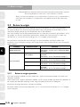
5.3.1
8
9
Contents
Return-to-origin operation
The return-to-origin methods include "stroke end + Z-phase detection" method and "stroke end
detection" method.
In the "stroke end + Z-phase detection" method, set the "Origin method" parameter to "SENSOR". In
the "stroke end detection" method, set the "Origin method" parameter to "TORQUE".
Each return-to-origin operation is described as follows.
For details about return-to-origin operation, see "5.3.2 Overall return-to-origin" or "5.3.3 Gripper
return-to-origin".
10
5-6
Chapter 5 Operation
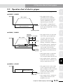
5.3 Return-to-origin
(1) Return-to-origin using the "stroke end + Z-phase detection" method
1
w
q
Return-to-origin
direction
e
Return-to-origin
start position
r
2
3
Stroke end
Z-phase of rotary encoder
q The return-to-origin can start from any position.
w Upon starting the return-to-origin, the axis starts moving in the return-to-origin direction.
e After the stroke end has been detected as the guide block has been lightly in contact with
the stroke end, the axis moves in the reverse direction until the Z-phase of the rotary
encoder is detected.
r When the Z-phase is detected, the axis moves again in the return-to-origin direction to
determine the origin position.
4
5
(2) Return-to-origin using the "stroke end detection" method.
w
q
e
Return-to-origin
direction
Return-to-origin
start position
6
7
8
Stroke end
q The return-to-origin can start from any position.
w Upon starting the return-to-origin, the axis starts moving in the return-to-origin direction.
e After the stroke end has been detected as the guide block has been lightly in contact with the
stroke end, the axis moves slightly in the reverse direction to determine the origin position.
c
CAUTION
During stroke end detection, if the guide block interferes with a foreign object or if a
load is applied to the guide block during return-to-origin, the stroke end may not be
detected correctly and the return-to-origin may be completed at an incorrect
position. The "stroke end detection" method is used only when the Z-phase
detection operation has a problem during return-to-origin using the "stroke end +
Z-phase detection" method.
Chapter 5 Operation
5-7
9
10
5.3 Return-to-origin
5.3.2
1
2
3
Overall return-to-origin
The following explains how to perform the return-to-origin of all axes with the incremental
specifications including the gripper axis.
For details about return-to-origin operation and related cautions, see the user’s manual for the
robot controller you are using.
c
CAUTION
To include the gripper axis in the overall return-to-origin, it is necessary to set the
"Include Gripper in Origin" parameter to "YES". (For details, see "6.3 Other parameter
details".)
1 Press the
(ORIGIN) key in the "MANUAL" mode.
The confirmation message will appear on the guide line.
(YES) key.
To start the return-to-origin, pres the
4
To cancel the return-to-origin, press the
(NO) key.
"RETURN-TO-ORIGIN CONFIRMATION" screen
MANUAL
5
50%[MG][S0H0J]
−−−−−−−−−−−−−−−−−−−−−−−−−−−−−−−−−−−−−−−−
Current position
*M1=
21593*M2=
*M4=
9875*m5=
8216*M3=
728*m6=
68468
814
6
Origin return again?
7
YES
NO
2 Verify the indication on the screen.
When all axes are put in the return-to-origin completion status, the message line will
change from the dotted line (-----) to the solid line (––––). Additionally, the machine
reference values for the axes other than the gripper axis are indicated. (Since the
gripper axis has no machine reference value, "0" is indicated.)
After that, press the axis movement key, etc. to indicate the current position of each
axis on the screen.
8
"RETURN-TO-ORIGIN COMPLETION" screen
MANUAL
9
50%[MG][S0H0J]
Machine reference (%)
M1=
50 M2=
M4=
52 m5=
51 M3=
0 m6=
48
0
10
POINT
5-8
Chapter 5 Operation
PALLET
ORIGIN
VEL+
VEL−
5.3 Return-to-origin
TIP
If the dotted line (----) remains on the message line, this means that there is an axis
with the absolute specifications and the absolute reset of this axis is incomplete. If
this occurs, perform the absolute reset of the target axis.
5.3.3
1
Gripper return-to-origin
2
The following explains how to perform the return-to-origin of only the gripper axis.
1 Select the "MANUAL>GORIGIN" mode.
Select the "MANUAL" mode and press the
(GORIGIN) key. The "MANUAL>GORIGIN"
mode screen will appear. (The figure below shows the screen when two grippers are
used.)
3
"MANUAL>GORIGIN" mode screen
MANUAL>GORIGIN
4
50%[MG][S0H0J]
−−−−−−−−−−−−−−−−−−−−−−−−−−−−−−−−−−−−−−−−
Press F.Key to gripper for origin
G1=NG/SENSOR
G2=NG/SENSOR
ALL
G1
5
G2
6
2 Select an axis you want to perform the return-to-origin.
To start the return-to-origin of the gripper 1, press the
start the return-to-origin of the gripper 2, press the
(G1) key. Accordingly, to
(G2) key.
7
When you want to perform the return-to-origin of both the grippers 1 and 2, press the
(ALL) key.
3 Confirm the message and press the
(YES) key.
8
The return-to-origin of the gripper axis you have selected is then started.
"RETURN-TO-ORIGIN CONFIRMATION" screen
MANUAL>GORIGIN
9
50%[MG][S0H0J]
−−−−−−−−−−−−−−−−−−−−−−−−−−−−−−−−−−−−−−−−
Starting origin search.
10
Origin return again?
YES
NO
Chapter 5 Operation
5-9
5.4 Emergency stop
4 Verify that the return-to-origin is complete.
1
When "OK" is indicated on the screen, this means that the return-to-origin is complete.
"MANUAL>GORIGIN" mode screen
MANUAL>GORIGIN
2
Gripper origin result
G1=OK
G2=OK
3
4
5
ALL
5.4
7
G1
G2
Emergency stop
The operation when the emergency stop button on the RPB is pressed may vary depending on the
set value of the "Gripper servo when E.stop" parameter as described below. (For details, see "6.3
Other parameter details".)
Make an appropriate setting suitable for the application.
Set value
6
50%[MG][S0H0J]
Function
ON
Only the electric gripper axis remains servo on. Other axes are
servo off. When the emergency stop button is pressed, the gripper
continues holding the workpiece since the servo is not turned off.
OFF
All axes including the electric gripper axis are servo off.
For details about how to use the emergency stop button on the RPB, see the user’s manual for robot
controller.
8
9
10
5-10
Chapter 5 Operation
5.5 Status monitor
5.5
Status monitor
You can verify the gripper status through the status monitor of the RPB. To verify the gripper status,
follow the steps below.
1 Press the
button on the RPB.
The current input status is indicated in the data area (3rd to 7th lines) on the RPB
screen.
Example of input status indication
MANUAL
50%[MG][SOHOJ]
DI monitor
DI0() =&B00000101
DI1() =&B00000010
DI2() =&B00000101
DI3() =&B00000101
DI4()
DI5()
DI6()
DI7()
=&B00000000
=&B00000000
=&B00000000
=&B00000000
DISPLAY KEY ー> NEXT PAGE
LOWER + DISPLAY KEY ー> PREV PAGE
POINT
2 Press the
PALLET
VEL+
VEL−
key again.
Every time the
key is pressed, the monitor indication is changed sequentially as
shown below.
DI monitor → DO monitor → MO monitor → LO/TO monitor → SI monitor → SO monitor
→ SIW monitor → SOW monitor → Variable monitor → Task monitor → Gripper1 →
(Gripper2) → Current monitor → Normal screen
n
NOTE
• The status monitor for the Gripper1 and/or Gripper2 is indicated only when the
electric gripper options are set.
• Every time the
+
keys are pressed, the monitor indication is changed in
the reverse order of that shown above.
Chapter 5 Operation
5-11
5.5 Status monitor
3 Press the
1
key several times until the gripper status monitor is
indicated.
TIP
Pressing the
+
keys on the normal screen will indicate the gripper status
monitor quickly.
2
Example of gripper status monitor indication
MANUAL
50%[MG][SOHOJ]
Gripper1
Servo
Origin
Emg.Stop
Ready
3
4
=1
=1
=1
=1
ZON
HOLD
INPOS
BUSY
=1
=1
=0
=0
Error No.
0x0000
Alarm No.
0x0000
DISPLAY KEY ー> NEXT PAGE
LOWER + DISPLAY KEY ー> PREV PAGE
5
POINT
•
Origin
Emg.Stop
Ready
Servo
status
Return- Emergency READY
stop
to-origin
signal
status
status
0
Servo
OFF
Incomplete
1
Servo
ON
Complete
Contents
7
VEL+
VEL−
Meaning of each status
Servo
6
PALLET
ZON
HOLD
INPOS
BUSY
ZON
signal
HOLD
signal
INPOS
signal
BUSY
signal
Emergency
Beyond
Beyond
Preparing
Release
Complete
stop
area
area
Cancel
Correct
Within
Holding
area
Within
area
Running
• Ready signal : This signal becomes "1" when the gripper is put in the
preparation completion status.
• ZON signal
: This signal becomes "1" when the gripper holds a workpiece
within the predetermined area.
• HOLD signal : This signal becomes "1" when the gripper holds a workpiece.
• INPOS signal : This signal shows that the gripper reaches the target position
after completion of the return-to-origin or positioning operation.
The signal also becomes "1" when the gripper reaches the
target position without holding of a workpiece by the gripper
movement operation command.
• BUSY signal : This signal becomes "1" during operation of the gripper.
8
9
•
Error No.
Indicates relevant error No. if an error occurs in the gripper.
•
10
Alarm No.
Indicates relevant alarm No. if an alarm occurs in the gripper.
n
5-12
NOTE
Each status of the gripper can be output to the general-purpose DO/SO when the
"G1 status output (DO & SO)" and "G2 status (DO & SO)" parameters are set.
Chapter 5 Operation
6.1 Parameter list
6. Parameter settings
This section explains the parameters used for the electric gripper. There are two kinds of
parameters available, parameters to be set for each axis (axis parameters) and common parameters
(other parameters).
6.1
Parameter list
2
■ Axis parameters
No.
1
Name
Acceleration
coefficient
RPB display
Identifier
Accel. coefficient
ACCEL
[%]
Setting range
[Default setting]
1 to 100 [100]
2
+ software
limit
+Soft limit
[pulse]
3
- software
limit
-Soft limit [pulse] PLMT-
Robot type to 0 [0]
4
Tolerance
Tolerance
[pulse]
TOLE
1 to Robot type
[Robot type]
5
Origin
position shift
Origin shift
[pulse]
SHIFT
Robot type [0]
PLMT+
6
Return-toOrigin method
origin method
ORGSNS
7
Return-toOrigin direction
origin direction
ORGDIR
8
Holding
speed
9
Return-toorigin speed
Holding speed
[%]
(for Gripper)
Origin speed [%]
GORGVL
(for Gripper)
Manual holding
Manual
10
power[%]
holding power
(for Gripper)
11
Constant
move
distance
12 Limit width
HLDVEL
0 to Robot type
[Robot type]
SENSOR : Stroke
end and Z signal
detection
TORQUE : Stroke
end detection
[SENSOR]
--- : Open
+++ : Close
Ver.10.18 and later :
20 to 50
In earlier versions :
1 to 100
[Robot type]
Ver.10.18 and later :
20 to 50
In earlier versions :
1 to 50
[Robot type]
GMHLPW 30 to 100 [30]
Const. move dist
[mm]
CMVDST
(for Gripper)
Limit width [mm]
LMTWDH
(for Gripper)
1
Unit
Remarks
%
The upper limit
of the setting
pulse range may
vary depending
on the model.
The lower limit
of the setting
pulse range may
vary depending
on the model.
Positioning
pulse completion
distance
3
4
5
pulse
6
–
–
7
%
8
%
%
0.01 to 99.99
[Robot type]
mm
0.01 to 99.99
[Robot type]
mm
This parameter
is supported
by controller
Ver.10.19 and
later.
Chapter 6 Parameter settings
9
10
6-1
6.1 Parameter list
■ Other parameters
1
No.
1
2
2
3
3
Name
Gripper servo
when
emergency
stop
Include
Gripper in
Origin
Manual
Holding of
Gripper
RPB display
Identifier
Setting range
[Default setting]
Unit
Gripper servo
when E.stop
GEMGMD ON, OFF [ON]
–
Include Gripper
in Origin
GORGMD NO, YES [YES]
–
Manual Holding
of Gripper
INVALID, VALID
[INVALID]
–
INVALID, VALID
[VALID]
–
GMHLMD
4
4
G1 status
output
G1 status
G1STAT
output(DO & SO)
Off, 2 to 7, 10 to 15
[off]
–
5
G2 status
output
G2 status
G2STAT
output(DO & SO)
Off, 2 to 7, 10 to 15
[off]
–
5
6
7
8
9
10
6-2
Chapter 6 Parameter settings
Remarks
This parameter
is supported
by controller
earlier than
Ver.10.30.
This parameter
is supported
by controller
Ver.10.30 and
later.
This parameter
is supported
by controller
Ver.10.18 and
later.
This parameter
is supported
by controller
Ver.10.18 and
later.
6.2 Axis parameter details
6.2
c
Axis parameter details
CAUTION
Set the parameters correctly so that any excessive impact or moment is not applied
to the finger during operation. If applied, this may cause damage to the product or
service life to be shortened.
1. Accel coefficient [%] /ACCEL
1
2
The acceleration for the gripper movement by the movement command is set in the range of 1
to 100%. When the parameters are initialized, "100" is set for this parameter.
n
c
3
NOTE
If the top end swings when the gripper movement is accelerated, decreasing this
parameter value will suppress this swinging symptom.
CAUTION
When the acceleration coefficient is decreased, a period of time necessary to stop
the gripper in response to the stop command by the STOP key or interlock signal
becomes longer. So, do not decrease this acceleration coefficient extremely.
4
5
2. +Soft limit [pulse] /PLMT+
3. –Soft limit [pulse] /PLMTAn area where the gripper axis is able to move is set using the + software limit and - software
limit.
Before starting the point teaching or auto operation, make sure that the specified point data is
within the software limit range.
The set value of the selected axis is indicated on the 3rd line of the RPB display after its unit
has been converted.
c
n
7
CAUTION
• These parameters are very important since they determine the movable area of
the gripper axis. So, it is absolutely necessary to set accurate values.
• If the return-to-origin operation is not completed, the JOG operation of the gripper axis cannot be performed.
8
NOTE
The set value of the data related to the distance, such as point data, constant
movement distance, or limit width parameter is the total of values set for two
fingers.
As the electric gripper is operated, two fingers function at the same time. The value
of the point data, constant movement distance, or limit width parameter set for
one finger is 1/2 of its set value.
Example) When the limit width is set at 2.00 mm:
The limit width for each finger is 1.00 mm. The total of values set for two
fingers is 2.00 mm.
Chapter 6 Parameter settings
6
9
10
6-3
6.2 Axis parameter details
4. Tolerance [pulse] /TOLE
A tolerance range of the positioning completion is set for the target position when the
movement of the gripper axis is complete. This parameter is set to a value unique to each axis
when initialized.
When the gripper axis enters an area specified by the tolerance, this is determined as
positioning complete. So, when PTP operation commands are instructed continuously on the
program, the positioning completion time can be shortened as this value is made larger.
The set value of the selected axis is indicated on the 3rd line of the RPB display after its unit
has been converted.
1
2
3
4
c
n
5
6
CAUTION
• This parameter is very important since it determines the axis behavior near the
target position. So, it is absolutely necessary to set an accurate value.
• I f the tolerance range was reduced to a drastically small value, then the time
needed for robot positioning might vary.
• The maximum tolerance value is determined by the motor.
NOTE
The set value of the data related to the distance, such as point data, constant
movement distance, or limit width parameter is the total of values set for two
fingers.
As the electric gripper is operated, two fingers function at the same time. The value
of the point data, constant movement distance, or limit width parameter set for
one finger is 1/2 of its set value.
Example) When the limit width is set at 2.00 mm:
The limit width for each finger is 1.00 mm. The total of values set for two
fingers is 2.00 mm.
5. Origin shift [pulse] /SHIFT
The position after completion of the return-to-origin shifts only a value specified by this
parameter. When the parameters are initialized, "0" is set for this parameter.
Regardless of the origin shift set value, the current position at completion of the return-to-origin
is "0" [pulse].
7
8
n
9
10
6-4
NOTE
• This parameter is set to correct the deviation amount if the work position deviates
for some reason.
• Note that the origin shift parameter setting procedures for the gripper axis are
different from those for an axis other than the gripper axis.
• The set value of the data related to the distance, such as point data, constant movement distance, or limit width parameter is the total of values set for two fingers.
As the electric gripper is operated, two fingers function at the same time. The
value of the point data, constant movement distance, or limit width parameter
set for one finger is 1/2 of its set value.
Example) When the limit width is set at 2.00 mm:
The limit width for each finger is 1.00 mm. The total of values set for two
fingers is 2.00 mm.
Chapter 6 Parameter settings
6.2 Axis parameter details
c
CAUTION
• This parameter is very important since it determines the robot position. So, it is
absolutely necessary to set an accurate value. Additionally, change this parameter value only when required.
• If this parameter is changed, the gripper enters the return-to-origin incomplete status.
• This parameter is valid after the return-to-origin has been complete.
• Do not set a value larger than the software limit for the origin shift parameter.
• If the origin shift is changed, change also the software limits according to the shift
amount.
Example) When A pulse is set for the origin shift parameter assuming that
+ software limit is B pulse and - software limit is C pulse, change each
software limit as follows.
+ software limit (B - A) pulse
- software limit
(C - A) pulse
1
2
3
4
6. Origin method /ORGSNS
This parameter sets a method used for the return-to-origin of the gripper axis.
SENSOR (Sensor method) . ... "Stroke end + Z-phase signal detection" method is used
for the gripper axis (Default value)
5
TORQUE (Torque method) ...Origin detection method by mechanical stroke end
MARK (Mark method) .......... Torque method is set.
n
NOTE
When this parameter is set to the "Stroke end + Z-phase signal detection" method,
the gripper axis moves backward until the Z-phase signal is detected after the
stroke end has been detected.
6
7. Origin direction /ORGDIR
This parameter sets a direction in which the gripper axis performs the return-to-origin.
"- - - " ..... Guide block open direction becomes the return-to-origin direction.
In the manual movement, the guide block open direction is - (negative) direction.
"+++" �..... Guide block close direction becomes the return-to-origin direction.
In the manual movement, the guide block close direction is - (negative) direction.
c
CAUTION
• YAMAHA can accept no liability from problems arising due to changing the return-to-origin direction without consulting YAMAHA beforehand.
• Return-to-origin will be incomplete if this parameter is changed.
7
8
9
10
Chapter 6 Parameter settings
6-5
6.2 Axis parameter details
8. Holding speed [%] (for Gripper) /HLDVEL
This parameter sets the speed within the effective holding area in the range of 20 to 50% during
absolute position (or relative position) holding movement or holding movement of the gripper
axis. (See the figure explaining "Holding speed", "Constant movement distance", and "Limit
width" parameters on the following page.)
1
2
3
c
n
CAUTION
If a value larger than the maximum speed is set for this parameter, the holding
speed equals the maximum speed.
NOTE
For the RCX240 with a software version of earlier than Ver.10.18, the setting range is
1 to 100%.
9. Origin speed [%] (for Gripper) /GORGVL
4
5
This parameter sets the return-to-origin speed in the range of 20 to 50%.
n
NOTE
For the RCX240 with a software version of earlier than Ver.10.18, the setting range is
1 to 50%.
10. Manual holding power [%] (for Gripper) /GMHLPW
This parameter sets the holding power during manual movement in the range of 30 to 100%.
6
7
n
11. Const. move dist. [mm] (for Gripper) /CMVDST
This parameter sets the constant movement distance during absolute position (or relative
position) holding movement or holding movement of the gripper axis. The gripper moves from
a position where is the constant movement distance back from the target position (holding
position) at the speed specified by the "Holding speed [%] (for Gripper)" parameter. (See the
figure explaining "Holding speed", "Constant movement distance", and "Limit width" parameters
on the following page.)
8
9
NOTE
• This parameter is valid only when a software version shown below is installed.
RCX240 Ver.10.19 or later
• For details about holding operation during manual movement, see the "Manual
Holding of Gripper" parameter of other parameters.
n
10
6-6
NOTE
The set value of the data related to the distance, such as point data, constant
movement distance, or limit width parameter is the total of values set for two fingers.
As the electric gripper is operated, two fingers function at the same time. The value
of the point data, constant movement distance, or limit width parameter set for
one finger is 1/2 of its set value.
Example) When the limit width is set at 2.00 mm:
The limit width for each finger is 1.00 mm. The total of values set for two
fingers is 2.00 mm.
Chapter 6 Parameter settings
6.2 Axis parameter details
12. Limit width [mm] (for Gripper) /LMTWDH
This parameter sets the limit width during absolute position (or relative position) holding
movement or constant speed movement of the holding operation of the gripper axis.
The gripper moves only the limit width at the speed specified by the "Holding speed [%] (for
Gripper)" parameter after it has exceeded the target position (holding position). (See the figure
explaining "Holding speed", "Constant movement distance", and "Limit width" parameters on
the following page.)
n
NOTE
• If the gripper axis exceeds the effective holding area, it stops at a position of
"movement amount + limit width". At this time, the HOLD signal is OFF and the
INPOS signal is ON. When the gripper axis stops within the effective holding area,
the ZON signal is also ON.
• The set value of the data related to the distance, such as point data, constant movement distance, or limit width parameter is the total of values set for two fingers.
As the electric gripper is operated, two fingers function at the same time. The
value of the point data, constant movement distance, or limit width parameter
set for one finger is 1/2 of its set value.
Example) When the limit width is set at 2.00 mm:
The limit width for each finger is 1.00 mm. The total of values set for two
fingers is 2.00 mm.
"Holding speed", "Constant movement distance", and "Limit width" parameters
Constant
movement
distance Limit width
Speed
1
2
3
4
5
6
Max. speed
Effective holding area
7
Holding speed
Movement distance
Distance
Holding position
8
9
10
Chapter 6 Parameter settings
6-7
6.3 Other parameter details
6.3
1
Other parameter details
1. Gripper ser vo when E.stop /GEMGMD
This parameter sets the servo status of the gripper axis when the emergency stop button is
pressed.
2
ON.. ......... The servo of the gripper axis does not turn off when the emergency stop button is
pressed.
Since the servo does not turn off even when the emergency stop button is
pressed, the gripper continues to hold the workpiece.
OFF.. ........ The servo of the gripper axis turns off when the emergency stop button is pressed.
3
2. Include Gripper in Origin /GORGMD
This parameter sets whether or not the gripper axis is included in the overall robot return-toorigin operation.
NO.. ......... The gripper axis is not included in the return-to-origin that is started by pressing
the [F3] (ORIGIN) key in the "MANUAL" mode.
4
YES.......... The gripper axis is included in the return-to-origin that is started by pressing the
[F3] (ORIGIN) key in the "MANUAL" mode.
5
n
6
7
8
9
NOTE
• If there are no axes with the incremental specifications other than the gripper
axis when this parameter is set at "NO", the [F3] (ORIGIN) key menu is not
indicated in the "MANUAL" mode. At this time, press the [F14] (G ORIGIN) key in
the "MANUAL" mode to perform the return-to-origin of the gripper axis.
• This parameter setting is valid even when the return-to-origin (*) is started from a
command other than the RPB as described below.
* • Return-to-origin by DI14 or DI17
• Return-to-origin by online command (@ORIGIN, @ORGRTN, or @ORGRTN2)
• Return-to-origin by robot language (ORIGIN)
• Return-to-origin by return-to-origin command of IO commands
• Return-to-origin by return-to-origin command of remote commands
3. Manual Holding of Gripper /GMHLMD
This parameter sets whether or not a workpiece is held during manual movement.
INVALID.. . The holding operation is invalid during manual movement.
If the gripper holds a workpiece during manual movement, "26.1: Gripper Over
load" occurs and the gripper cannot hold a workpiece.
VALID ..... The holding operation is valid during manual movement.
The gripper can hold a workpiece during manual movement.
10
6-8
Chapter 6 Parameter settings
6.3 Other parameter details
c
n
CAUTION
When this parameter is set to "VALID", the operation mode of the manual movement
changes to the holding movement. So, the movement distance during inching
operation does not interlock with the manual movement speed (%).
The inching operation with the holding operation set at "INVALID" is the same as the
axes other than the electric gripper.
When this parameter is set to "INVALID", the movement distance during inching
operation interlocks with the manual movement speed.
For details, see "5.2 Manual movement".
NOTE
• This parameter is valid only when a software version shown below is installed.
RCX240 Ver.10.19 or later
• The holding power during manual movement can be set using the axis
parameter, "Manual holding power [%] (for Gripper)".
1
2
3
4
4. G1 status output (DO & SO) /G1STAT
5. G2 status output (DO & SO) /G2STAT
These parameters set whether or not the eclectic gripper dedicated signals (status signals) are
output to general-purpose DO/SO.
The set values are as follows.
Setting
Meaning
Off (Default value)
The electric gripper status is not output.
2 to 7, 10 to 15
The electric gripper status is output to the DO and SO of the
specified port.
For example, when "10" is specified, the electric gripper status
information is output to DO10() and SO10().
The bit assignments are shown in the table below.
6
7
The electric gripper status information is output to a specified port as described in the table
below.
For details about each status, see "5.5 Status monitor".
Bit
5
Signal name
Value
0
1
OFF
ON
7
Servo status
6
Return-to-origin status
Incomplete
Complete
5
Emergency stop status
Emergency stop
Cancel
4
READY signal
3
ZON signal
2
Preparing
Correct
Beyond area
Within area
HOLD signal
Release
Holding
1
INPOS signal
Beyond area
Within area
0
BUSY signal
Complete
Running
8
9
10
Chapter 6 Parameter settings
6-9
6.3 Other parameter details
1
n
2
3
4
NOTE
• This parameter is valid only when a software version shown below is installed.
RCX240 Ver.10.18 or later
• When the same port as the area check output port is specified, a logical OR
of the area check information and status information is output.
• When the same port as the error output port is specified, a logical OR of the error
and status information is output.
• When the same port as the battery alarm output port is specified, a logical OR of
the battery alarm and status information is output.
• When a serial board, such as CC-Link is added to the option board, the status
information is also output to SO of the same port as DO.
• When the individual axis return-to-origin option by general-purpose DI/SI
(SYSTEM>OPTION>DI.ORG) is used and the same port as the return-to-origin completion output "Done output port (DO & SO)" is specified, the logical OR of
the return-to-origin completion output and this status output is output.
For details, see the user’s manual for YAMAHA robot controller RCX240.
5
6
7
8
9
10
6-10
Chapter 6 Parameter settings
7.1 Point data input and editing
7. Gripper point data creation
1
This section explains how to create positioning point data of the gripper. Since the gripper is
controlled as an auxiliary axis of the robot, the point data for the auxiliary axis is set.
For details about how to display or edit the point data, see the user’s manual for the robot
controller you are using.
n
7.1
NOTE
The set value of the data related to the distance, such as point data, constant
movement distance, or limit width parameter is the total of values set for two fingers.
As the electric gripper is operated, two fingers function at the same time. The value
of the point data, constant movement distance, or limit width parameter set for
one finger is 1/2 of its set value.
Example) When the gripper current position is 0.00 mm and the gripper axis moves
to the 10.00mm-position using the absolute position movement:
Each finger moves 5.00 mm and the total movement of both fingers is
10.00 mm.
2
3
4
Point data input and editing
5
1 Select the "MANUAL>POINT" mode.
2 Use the cursor key (
3 Press the
/
) to select a point you want to input or edit.
(EDIT) key.
The cursor is indicated at the left end of the data on the point line you have selected.
6
Editing point data
MANUAL>POINT>EDIT
x
y
P7
= 100.00 250.00
P8
=
P9
= 122562 −24654
COMNT:
[POS]
UNDO
0
0
JUMP
7
50%[MG][S0H0J]
z
r
15.00
30.00
2535
[
0
−13711
]
8
0
9
10
Chapter 7 Gripper point data creation
7-1
7.1 Point data input and editing
4 Enter point data of the axis set as gripper.
1
The data, x, y, z, r, a, and b is separated by a space. The data input format is as follows.
2
3
4
n
•
To enter data in units of pulses, enter up to 8-digit integer.
(When the number of display digits is set to "8" in the "SYSTEM>PARAM" mode, 8-digit
data is indicated on the screen.)
•
To enter data in units of millimeters, enter a numeric value consisting of 5-digit or less
integer and 2-digit or less decimal.
(When the number of display digits is set to "8" in the "SYSTEM>PARAM" mode, 8-digit
data is indicated on the screen.)
NOTE
• "0" (zero) is automatically entered for an axis without data input.
• The error message "Digit number error" appears when the data format is wrong.
Enter it in the correct format.
5 Set the data you have entered.
Press the
, cursor up/down key (
/
), or page up/down key (
set the point data you have entered.
Press
if you want to cancel the point data input.
5
6
7
8
9
10
7-2
Chapter 7 Gripper point data creation
/
) to
7.2 Point data input by teaching
7.2
Point data input by teaching
1
You can take the current gripper position to the point data in the "MANUAL>POINT" mode.
n
NOTE
Point data teaching cannot be performed when return-to-origin is incomplete.
Perform point teaching after performing return-to-origin.
2
1 Move the cursor to a point number you want to input data.
Point data teaching (1)
MANUAL>POINT
x
P7
= 100.00
P8
= 220.00
P9
= 400.00
COMNT:
[POS]
EDIT
y
250.00
150.00
200.00
50.00 150.00
TEACH
JUMP
3
100%[MG][S0H0X]
z
r
15.00
30.00
115.00
90.00
15.00 −30.00
[
115.00
VEL+
4
]
90.00
VEL−
5
2 Select a point for the gripper axis.
Use the cursor key (
/
), or the
(AXIS ←) or
(AXIS →) key to make the
selection so that the point value of the auxiliary axis, to which the gripper axis is
assigned, is highlighted. Note that you can specify only a point number when no point
data is set.
6
Point data teaching (2)
MANUAL>POINT
y
P7
= 250.00
P8
= 150.00
P9
= 200.00
z
15.00
115.00
15.00
COMNT:
[POS] 150.00 115.00
EDIT
TEACH
JUMP
7
100%[MG][S0H0X]
r
a
30.00
2.00
90.00
9.00
−30.00
10.00
[
90.00
VEL+
8
]
11.23
VEL−
9
3 Use the JOG key to move the gripper axis.
The current position "[POS]" on the 14th line of the screen changes as the gripper
moves.
10
Chapter 7 Gripper point data creation
7-3
7.2 Point data input by teaching
4 Press the
1
(TEACH) key when the gripper reaches the target point.
The current gripper position is taught to the specified point.
In the teaching by axis, it is necessary to select the same coordinate system as that of
the teaching point. So, when the point data is in units of millimeters, the current position
must also be in units of millimeters.
If the point data already exists at the specified point, the message, "Overwrite point
OK?", will appear on the guide line.
2
Press
(YES) to perform the teaching.
Press
(NO) if you want to cancel the teaching input.
Point data teaching (3)
3
4
5
MANUAL>POINT>TEACH
y
z
P7
= 250.00
15.00
P8
= 150.00 115.00
P9
= 200.00
15.00
100%[MG][S0H0X]
r
a
30.00
2.00
90.00
9.00
−30.00
10.00
COMNT:
[POS] 150.00 115.00
Overwrite point OK?
[
90.00
YES
]
6.86
NO
After teaching, the point data number designation automatically moves to the next
line.
6
7
8
9
10
7-4
Chapter 7 Gripper point data creation
7.3 Point data input by direct teaching
7.3
Point data input by direct teaching
1
As the robot servo is turned off, the point data of a position where you have moved the gripper
manually can be taken.
w
WARNING
• To perform the direct teaching in the emergency stop status, it is necessary to set the "Gripper servo when E.stop" parameter to "OFF". (For
details, see "6.3 Other parameter details".)
•Before starting the direct teaching, always put the emergency stop button in the pressed status.
2
3
1 Put in the emergency stop status.
Press the emergency stop button on the RPB.
2 Perform the point teaching in the "MANUAL>POINT" mode.
For details about teaching, see "7.2 Point data input by teaching".
At this time, however, since the JOG key cannot be used, move the gripper manually.
7.4
Point data trace
5
You can check the point data position you have entered by moving the gripper actually.
Before starting the point data trace, press the
(TRACE) key in the "MANUAL>POINT" mode to
change to the "AUTO>POINT>TRACE" mode.
After that, use the point trace function to check the point data position.
For details, see the user’s manual for the robot controller you are using.
n
4
6
NOTE
• When pressing the
(MODIFY) key in the "AUTO>POINT" mode, the mode is
7
returned to the mode hierarchy before trace, "MANUAL>POINT" mode.
• When the "MANUAL>POINT" mode is changed to the "AUTO>POINT" mode,
pressing the
key will return to the "MANUAL>POINT" mode.
8
9
10
Chapter 7 Gripper point data creation
7-5
MEMO
7-6
Chapter 7 Gripper point data creation
8.1 Robot language command list
8. Robot language commands
This section explains the dedicated robot language commands used for YAMAHA electric gripper.
Refer to the YAMAHA Robot Controller RCX Series Programming Manual for robot language
information beyond basic items such as the robot language command statement format, variables,
and constants. Always refer to the above programming manual when performing programming
operations.
8.1
Robot language command list
2
Function
Language
command name
Format
Moves to an absolute position.
GDRIVE
1
GDRIVE (<Gripper number>, <Position>
) [, (<Gripper number>, <Position>
) ] [, Option]
< Point expression>
< Point expression>
3
Moves to a relative position.
GDRIVEI
GDRIVEI (<Gripper number>, < Movement amount> ) [, (<Gripper number>, < Movement amount> ) ] [, Option]
< Point expression>
< Point expression>
Moves to an absolute position with holding of a workpiece.
GHOLD
GHOLD (<Gripper number>, <Position>
) [, (<Gripper number>, <Position>
) ] [, Option]
< Point expression>
< Point expression>
4
Moves to a relative position with holding of a workpiece
GHOLDI
GHOLDI (<Gripper number>, < Movement amount> ) [, (<Gripper number>, < Movement amount> ) ] [, Option]
< Point expression>
< Point expression>
Moves at a constant speed with holding of a workpiece. (Open)
GOPEN
GOPEN (<Gripper number>) [, (<Gripper number>)] [, Option]
Moves at a constant speed with holding of a workpiece. (Close)
GCLOSE
GCLOSE (<Gripper number>) [, (<Gripper number>)] [, Option]
Returns the gripper axis to its origin.
GORIGIN
6
GORIGIN [(<Gripper number>)]
Obtains the status.
GSTATUS
GSTATUS (<Gripper number>)
Returns to the origin.
ORIGIN
ORIGIN
7
Obtains the current position of the main group (Joint coordinates).
WHERE
WHERE
Obtains the current position of the sub group (Joint coordinates).
WHERE2
WHERE2
Obtains the current position of the main group (Cartesian coordinates).
WHRXY
8
WHRXY
Obtains the current position of the sub group (Cartesian coordinates).
WHRXY2
n
5
WHRXY2
NOTE
The gripper number is a serial number starting with "1". If multiple grippers are used,
a board with a smaller option slot number set on the gripper control board is "1" and
a board with a larger option slot number is "2".
Example: When two gripper control boards are used:
Option slot
OP.1
OP.2
OP.3
OP.4
Board setting
–
Gripper control board
–
Gripper control board
Gripper number
–
10
1
–
2
Chapter 8 Robot language commands
9
8-1
8.2 Robot language command details
8.2
1
Robot language command details
This section explains each robot language command.
8.2.1
Dedicated commands for gripper axis
GDRIVE
2
GDRIVE ( <Gripper number> , <Position>
<Point expression>
) [, ( <Gripper number> , <Position>
)] [, Option]
<Point expression>
<Gripper number> Range: 1 to 2
3
Function
This command moves the electric gripper axis to an absolute position.
Explanation
After the operations of all gripper axes specified by <Gripper number> have been complete,
the specified gripper axis starts moving. When the gripper axis reaches the target position,
the command is terminated. The axis can also be specified by the variable.
When multiple axes are specified, these axes do not reach their target positions at the same
time.
4
Example:
5
GDRIVE (1, P10)�������� Gripper 1 moves from the current position to a position specified
by P10.
Point data setting
• Direct coordinate data input
6
Directly specify coordinate data in <Position>.
When the coordinate data is an integer, the movement units are viewed as "pulses". When the
coordinate data is a real number containing a decimal point, the units are viewed as "mm".
According to these units, the gripper axis will move. When the units are viewed as "mm", the
gripper axis moves to the position converted for each axis relative to the 0-pulse position.
7
Example:
GDRIVE (1, 500)�������� Gripper 1 moves from the current position to the 500-pulse
position.
GDRIVE (2, 10.0)������� Gripper 2 moves from the current position to the 10.0mm-position.
8
• Point definition
Specify a movement position in <Point expression>. Axis number data, to which the gripper
specified by <Gripper number> is assigned, is used.
The gripper moves to the position determined by the units used for the point expression.
When the units are viewed as "mm", the gripper axis moves to the position converted for
each axis relative to the 0-pulse position.
9
Example:
GDRIVE (1, P10)�������� Gripper 1 moves from the current position to the position specified
by P10.
10
8-2
Chapter 8 Robot language commands
8.2 Robot language command details
n
NOTE
The coordinate data specified as movement destination is the total of values set for
two fingers.
As the electric gripper is operated, two fingers function at the same time. The
coordinate value of the point data set for one finger is 1/2 of its set value.
Example) When the gripper current position is 0.00 mm and the gripper axis moves
to the 10.00mm-position using the absolute position movement:
Each finger moves 5.00 mm and the total movement of both fingers is
10.00 mm.
Option types
2
3
• Speed setting
SPEED
S
1
= <Speed>
Range: 1 to 100 (Unit: %)
4
Specify a program movement speed in <Speed>. If not specified, the program movement
speed uses the current set value. (Default value: 100%. The program movement speed can be
set in the range of 1 to 100% by the SPEED statement/SPEED2 statement.)
The movement speed is determined by multiplying the auto movement speed by the program
movement speed. This value is limited to 20 to 100%. If the value is less than 20%, it is then
set to 20%.
This option is enabled only for the specified GDRIVE statement.
5
Example:
6
GDRIVE (1, 5.0), S=30�����Gripper 1 moves from the current position to the 5.0mmposition with the program speed set at 30%.
GDRIVEI
GDRIVEI ( <Gripper number> , <Movement amount> ) [, ( <Gripper number> , <Movement amount> )] [, Option]
<Point expression>
<Point expression>
7
<Gripper number> Range: 1 to 2
Function
8
This command moves the electric gripper axis to a relative position.
Explanation
After the operations of all gripper axes specified by <Gripper number> have been complete,
the specified gripper axis starts moving. When the gripper axis reaches the specified
movement amount, the command is terminated. The axis can also be specified by the
variable. When multiple axes are specified, these axes do not reach their target positions at
the same time.
9
Example:
GDRIVEI (1, P10)������� Gripper 1 moves the movement amount specified by P10 from the
current position.
Chapter 8 Robot language commands
8-3
10
8.2 Robot language command details
Point data setting
• Direct coordinate data input
1
Directly specify coordinate data in <Movement amount>.
When the coordinate data is an integer, the movement units are viewed as "pulses". When
the coordinate data is a real number containing a decimal point, the units are viewed as
"mm". According to these units, the gripper axis will move. When the units are viewed as
"mm", the gripper axis moves the movement amount converted for each axis relative to the
0-pulse position.
2
Example:
GDRIVEI (1, 500)������� Gripper 1 moves from the current position to the +500-pulse position.
GDRIVEI (2, 10.0)������ Gripper 2 moves from the current position to the +10.0mm-position.
3
• Point definition
Specify a movement amount in <Point expression>. Axis number data, to which the gripper
specified by <Gripper number> is assigned, is used.
The gripper moves the movement amount by the units used for the point expression. When
the units are viewed as "mm", the gripper axis moves the movement amount converted for
each axis relative to the 0-pulse position.
4
Example:
5
GDRIVEI (1, P10)������� Gripper 1 moves the movement amount specified by P10 from the
current position.
n
6
7
NOTE
The coordinate data specified as movement destination is the total of values set for
two fingers.
As the electric gripper is operated, two fingers function at the same time. The
coordinate value of the point data set for one finger is 1/2 of its set value.
Example) When the gripper axis moves to the +10.00mm-position from the current
position using the relative position movement:
"+ 5.00 mm" is specified for each finger and the total movement of both
fingers is "+ 10.00 mm".
Option types
• Speed setting
8
SPEED
S
= <Speed>
Range: 1 to 100 (Unit: %)
Specify a program movement speed in <Speed>. If not specified, the program movement
speed uses the current set value. (Default value: 100%. The program movement speed can be
set in the range of 1 to 100% by the SPEED statement/SPEED2 statement.)
The movement speed is determined by multiplying the auto movement speed by the program
movement speed. This value is limited to 20 to 100%. If the value is less than 20%, it is then
set to 20%.
This option is enabled only for the specified GDRIVEI statement.
9
10
Example:
8-4
GDRIVEI (1, 5.0), S=30����Gripper 1 moves from the current position to the +5.0mmposition with the program speed set at 30%.
Chapter 8 Robot language commands
8.2 Robot language command details
GHOLD
GHOLD ( <Gripper number> , <Position>
<Point expression>
) [, ( <Gripper number> , <Position>
)] [, Option]
<Point expression>
1
<Gripper number> Range: 1 to 2
Function
This command moves the gripper axis to a position close to the specified position at a
trapezoidal acceleration/deceleration and moves it at a holding speed specified by the
parameter immediately before holding. In this motion, the holding power can be specified by
the command option <Power>.
Explanation
After the operations of all gripper axes specified by <Gripper number> have been complete,
the specified gripper starts moving. When it is judged that the gripper reaches the target
position or holds a workpiece, the command is terminated. The operation completion
conditions can be checked using GSTATUS.
Example:
2
3
4
GHOLD (1, P10)�������� Gripper 1 moves from the current position to a position specified
by P10.
5
Point data setting
• Direct coordinate data input
Directly specify coordinate data in <Position>.
When the coordinate data is an integer, the movement units are viewed as "pulses". When the
coordinate data is a real number containing a decimal point, the units are viewed as "mm".
According to these units, the gripper axis will move. When the units are viewed as "mm", the
gripper axis moves to the position converted for each axis relative to the 0-pulse position.
6
Example:
GHOLD (1, 500)�������� Gripper 1 moves from the current position to the 500-pulse
position.
GHOLD (2, 10.0)������� Gripper 2 moves from the current position to the 10.0mm-position.
7
• Point definition
Specify a movement position in <Point expression>. Axis number data, to which the gripper
specified by <Gripper number> is assigned, is used.
The gripper moves to the position determined by the units used for the point expression.
When the units are viewed as "mm", the gripper axis moves to the position converted for
each axis relative to the 0-pulse position.
Example:
GHOLD (1, P10)�������� Gripper 1 moves from the current position to the position specified
by P10.
8
9
10
Chapter 8 Robot language commands
8-5
8.2 Robot language command details
1
n
2
3
NOTE
• Set a workpiece holding position (target position) so that it does not exceed the
value that the limit width is subtracted from the software limit.
• The coordinate data specified as movement destination is the total of values set
for two fingers.
As the electric gripper is operated, two fingers function at the same time. The
coordinate value of the point data set for one finger is 1/2 of its set value.
Example) When the gripper current position is 0.00 mm and the gripper axis moves to the 10.00mm-position using the absolute position movement:
Each finger moves 5.00 mm and the total movement of both fingers is
10.00 mm.
Option types
• Speed setting
SPEED
S
4
= <Speed>
Range: 1 to 100 (Unit: %)
Specify a program movement speed in <Speed>. If not specified, the program movement
speed uses the current set value. (Default value: 100%. The program movement speed can be
set in the range of 1 to 100% by the SPEED statement/SPEED2 statement.)
The movement speed is determined by multiplying the auto movement speed by the program
movement speed. This value is limited to 20 to 100%. If the value is less than 20%, it is then
set to 20%.
This option is enabled only for the specified GHOLD statement.
5
6
Example:
GHOLD (1, 5.0), S=30�����Gripper 1 moves from the current position to the 5.0mmposition with the program speed set at 30%.
7
• Power setting
T = <Power>
Range: 30 to 100 (Unit: %)
8
Specify a workpiece holding force in <Power>. If not specified, the power becomes 100%.
If a value less than 30% is set in the RCX240 with a software version of Ver. 10.18 or later,
the power is then set to 30%.
This option is enabled only for the specified GHOLD statement.
9
Example:
GHOLD (1, 5.0), T=40����� Gripper 1 moves from the current position to the 5.0mmposition. The holding power is 40%.
10
8-6
Chapter 8 Robot language commands
8.2 Robot language command details
Example:
-software limit = 0.00 mm
+software limit = 14.3 mm
Limit width
= 0.4 mm
1
When the parameters are set as shown above:
GHOLD(1, 0.0)����������"27.32: Gripper Soft limit over" occurs and the operation
cannot be performed.
2
GHOLD(1, 14.3)�������� "27.32: Gripper Soft limit over" occurs and the operation
cannot be performed
GHOLD(1, 0.4)����������If the gripper does not hold a workpiece, it stops at the 0.0mmposition.
GHOLD(1, 13.9)�������� If the gripper does not hold a workpiece, it stops at the
14.3mm-position.
c
CAUTION
Set an appropriate workpiece holding force (%) for the gripper movement
command so that any excessive impact or moment is not applied to the finger
during operation. If applied, this may cause damage to the product or service life
to be shortened.
3
4
5
GHOLDI
GDRIVEI ( <Gripper number> , <Movement amount> ) [, ( <Gripper number> , <Movement amount> )] [, Option]
<Point expression>
<Point expression>
6
<Gripper number> Range: 1 to 2
Function
This command moves the gripper axis to a position close to the specified movement amount
at a trapezoidal acceleration/deceleration and moves it at a holding speed specified by the
parameter immediately before holding. In this motion, the holding power can be specified by
the command option <Power>.
7
Explanation
After the operations of all gripper axes specified by <Gripper number> have been complete,
the specified gripper axis starts moving. When it is judged that the gripper reaches the
specified movement amount or holds a workpiece, the command is terminated.
The operation completion conditions can be checked using GSTATUS.
8
Example:
GHOLDI (1, P10)������� Gripper 1 moves the movement amount specified by P10 from the
current position.
9
10
Chapter 8 Robot language commands
8-7
8.2 Robot language command details
Point data setting
• Direct coordinate data input
1
Directly specify coordinate data in <Movement amount>.
When the coordinate data is an integer, the movement units are viewed as "pulses". When
the coordinate data is a real number containing a decimal point, the units are viewed as
"mm". According to these units, the gripper axis will move. When the units are viewed as
"mm", the gripper axis moves the movement amount converted for each axis relative to the
0-pulse position.
2
Example:
GHOLDI (1, 500)������� Gripper 1 moves from the current position to the +500-pulse position.
GHOLDI (2, 10.0)������ Gripper 2 moves from the current position to the +10.0mm-position.
3
• Point definition
Specify a movement amount in <Point expression>. Axis number data, to which the gripper
specified by <Gripper number> is assigned, is used.
The gripper moves the movement amount by the units used for the point expression. When
the units are viewed as "mm", the gripper axis moves the movement amount converted for
each axis relative to the 0-pulse position.
4
Example:
5
GHOLDI (1, P10)������� Gripper 1 moves the movement amount specified by P10 from the
current position.
n
6
7
8
NOTE
• Set a workpiece holding position (target position) so that it does not exceed the
value that the limit width is subtracted from the software limit.
• The coordinate data specified as movement destination is the total of values set
for two fingers.
As the electric gripper is operated, two fingers function at the same time. The
coordinate value of the point data set for one finger is 1/2 of its set value.
Example) When the gripper axis moves to the +10.00mm-position from the current position using the relative position movement:
"+ 5.00 mm" is specified for each finger and the total movement of
both fingers is "+ 10.00 mm".
Option types
• Speed setting
SPEED
S
= <Speed>
Range: 1 to 100 (Unit: %)
9
Specify a program movement speed in <Speed>. If not specified, the program movement
speed uses the current set value. (Default value: 100%. The program movement speed can be
set in the range of 1 to 100% by the SPEED statement/SPEED2 statement.)
The movement speed is determined by multiplying the auto movement speed by the program
10
movement speed. This value is limited to 20 to 100%. If the value is less than 20%, it is then
set to 20%.
This option is enabled only for the specified GHOLDI statement.
8-8
Chapter 8 Robot language commands
8.2 Robot language command details
Example:
GHOLDI (1, 5.0), S=30����Gripper 1 moves from the current position to the 5.0mmposition with the program speed set at 30%.
1
• Power setting
T = <Power>
Range: 30 to 100 (Unit: %)
2
Specify a workpiece holding force in <Power>. If not specified, the power becomes 100%.
If a value less than 30% is set in the RCX240 with a software version of Ver. 10.18 or later,
the power is then set to 30%.
This option is enabled only for the specified GHOLDI statement.
3
Example:
GHOLDI (1, 5.0), T=40���� Gripper 1 moves from the current position to the 5.0mmposition. The holding power is 40%.
4
Example:
-software limit = 0.00 mm
+software limit = 14.3 mm
Limit width
= 0.4 mm
When the parameters are set as shown above and the gripper current position is "0.00 mm":
GHOLDI (1, 14.3)������ " 27.32: Gripper Soft limit over" occurs and the operation
cannot be performed.
GHOLDI (1, 13.9)������ If the gripper does not hold a workpiece, it stops at the
14.3mm-position.
c
5
6
CAUTION
Set an appropriate workpiece holding force (%) for the gripper movement
command so that any excessive impact or moment is not applied to the finger
during operation. If applied, this may cause damage to the product or service life
to be shortened.
7
GOPEN
8
GOPEN (<Gripper number>) [, (<Gripper number>)] [, Option]
<Gripper number> Range: 1 to 2
Function
This command moves the gripper axis to the stroke end at a constant speed in the open
direction. In this motion, the holding power is specified by the command option <Power>.
9
Explanation
After the operations of all gripper axes specified by <Gripper number> have been complete,
the specified gripper axis starts moving. When it is judged that the gripper reaches the target
position or holds a workpiece, the command is terminated.
The operation completion conditions can be checked using GSTATUS.
Chapter 8 Robot language commands
8-9
10
8.2 Robot language command details
Example:
1
GOPEN (1)���������������� Gripper 1 moves from the current position in the open direction.
Option types
• Speed setting
SPEED
S
2
= <Speed>
Range: 1 to 100 (Unit: %)
Specify a program movement speed in <Speed>. If not specified, the program movement
speed uses the current set value. (Default value: 100%. The program movement speed can be
set in the range of 1 to 100% by the SPEED statement/SPEED2 statement.)
The movement speed is determined by multiplying the auto movement speed by the program
movement speed.
This value is limited as follows.
3
4
RCX240
Software version, earlier than Ver.10.18: The multiplication value is limited to 20 to 100%.
(If the value is less than 20%, it is set to 20%.)
Software version, Ver.10.18 or later:
5
The multiplication value is limited to 20 to 50%.
(If the value is less than 20%, it is set to 20%. If
the value is 50% or more, it is set to 50%.)
This option is valid only for the specified GOPEN statement.
Example:
GOPEN (1), S=30 ������ Gripper 1 moves from the current position in the open direction
with the program speed set at 30%.
6
• Power setting
T = <Power>
7
Range: 30 to 100 (Unit: %)
Specify a workpiece holding force in <Power>. If not specified, the power becomes 100%.
If a value less than 30% is set in the RCX240 with a software version of Ver. 10.18 or later,
the power is then set to 30%.
This option is enabled only for the specified GOPEN statement.
8
Example:
GOPEN (1), T=40������� Gripper 1 moves from the current position in the open direction.
The holding power is 40%.
9
c
10
8-10
CAUTION
Set an appropriate workpiece holding force (%) for the gripper movement
command so that any excessive impact or moment is not applied to the finger
during operation. If applied, this may cause damage to the product or service life
to be shortened.
Chapter 8 Robot language commands
8.2 Robot language command details
GCLOSE
1
GCLOSE (<Gripper number>) [, (<Gripper number>)] [, Option]
<Gripper number> Range: 1 to 2
Function
This command moves the gripper axis to the stroke end at a constant speed in the close
direction. In this motion, the holding power is specified by the command option <Power>.
2
Explanation
After the operations of all gripper axes specified by <Gripper number> have been complete,
the specified gripper axis starts moving. When it is judged that the gripper reaches the target
position or holds a workpiece, the command is terminated.
The operation completion conditions can be checked using GSTATUS.
3
Example:
GCLOSE (1)��������������� Gripper 1 moves from the current position in the close direction.
Option types
4
• Speed setting
SPEED
S
= <Speed>
5
Range: 1 to 100 (Unit: %)
Specify a program movement speed in <Speed>. If not specified, the program movement
speed uses the current set value. (Default value: 100%. The program movement speed can be
set in the range of 1 to 100% by the SPEED statement/SPEED2 statement.)
The movement speed is determined by multiplying the auto movement speed by the program
movement speed.
This value is limited as follows.
RCX240
Software version, earlier than Ver.10.18: The multiplication value is limited to 20 to 100%.
(If the value is less than 20%, it is set to 20%.)
Software version, Ver.10.18 or later:
The multiplication value is limited to 20 to 50%.
(If the value is less than 20%, it is set to 20%. If
the value is 50% or more, it is set to 50%.)
6
7
8
This option is valid only for the specified GCLOSE statement.
Example:
GCLOSE (1), S=30 ���� Gripper 1 moves from the current position in the close direction
with the program speed set at 30%.
9
10
Chapter 8 Robot language commands
8-11
8.2 Robot language command details
• Power setting
1
T = <Power>
Range: 30 to 100 (Unit: %)
Specify a workpiece holding force in <Power>. If not specified, the power becomes 100%.
If a value less than 30% is set in the RCX240 with a software version of Ver. 10.18 or later,
the power is then set to 30%.
This option is enabled only for the specified GCLOSE statement.
2
Example:
3
GCLOSE (1), T=40����� Gripper 1 moves from the current position in the close direction.
The holding power is 40%.
c
4
CAUTION
Set an appropriate workpiece holding force (%) for the gripper movement
command so that any excessive impact or moment is not applied to the finger
during operation. If applied, this may cause damage to the product or service life
to be shortened.
GORIGIN
5
GORIGIN [(<Gripper number>)]
<Gripper number> Range: 1 to 2
6
Function
This command executes the return-to-origin of the gripper with the specified number or
all grippers (all grippers in the main and sub groups). If the command execution is stopped
halfway, the return-to-origin is incomplete.
If <Gripper number> is not specified, the return-to-origin of all grippers is executed.
Example:
7
GORIGIN������������������ Starts the return-to-origin of all grippers.
GORIGIN (1)������������� Starts the return-to-origin of gripper 1
8
GSTATUS
GSTATUS [(<Gripper number>)]
<Gripper number> Range: 1 to 2
9
Function
This command obtains the status information on gripper with the specified number.
The obtained result is a value that each status is assigned to relevant bit. The meaning
of each bit is described in the table below. For details about each status, see "5.5 Status
monitor".
10
8-12
Chapter 8 Robot language commands
8.2 Robot language command details
Bit7
Meaning
Servo
status
Bit6
Returnto-origin
status
0
Servo OFF Incomplete
1
Servo ON
Complete
Bit5
Bit4
Bit3
Bit2
Bit1
Bit0
Emergency
stop status
READY
ZON
HOLD
INPOS
BUSY
Emergency
stop
Preparing
Cancel
Correct
Beyond
area
Within
area
Release
Holding
Beyond
area
Within
area
1
Complete
Running
2
Example:
● Operation branch after completion of gripper operation
GHOLD (1, 10.0)������������������������������� Moves gripper 1 from the current position to the
10.0mm-position.
3
STS% = GSTATUS (1) AND &B110������ Obtains the status information on gripper 1.
INP% = STS% AND &B10������������������� Obtains the status of the INPOS bit.
HLD% = STS% AND &B100��������������� Obtains the status of the HOLD bit.
IF INP% <> 0 THEN��������������������������� Checks the status of the INPOS bit.
4
*** Operation completion as the gripper reaches the target position. ***
ELSEIF HLD% <> 0 THEN������������������� Checks the status of the HOLD bit.
*** Operation completion as the gripper holds a workpiece. ***
ENDIF
5
6
7
8
9
10
Chapter 8 Robot language commands
8-13
8.2 Robot language command details
8.2.2
1
Other commands for gripper axis
ORIGIN
ORIGIN
2
Function
This command executes the return-to-origin of the axis with the incremental specifications.
The command also executes the absolute search operation for the axis with the semi-absolute
specifications. If there is an electric gripper axis, the return-to-origin of the electric gripper
can be performed by setting the parameters. If the command execution is stopped halfway,
the return-to-origin is incomplete.
When two robots are set, the return-to-origin and absolute search operations of the sub robot
group are performed after the return-to-origin and absolute search operations of the main
group have been complete.
3
Example:
4
ORIGIN�������������������� Starts the return-to-origin of the axis with the incremental specifications.
(For the axis with the semi-absolute specifications, the absolute
search operation is performed.)
WHERE/WHERE2
5
WHERE
WHERE2
Function
This command reads out the current position of the main/sub group arm in joint coordinates
(pulses).
6
Example:
P10 = WHERE������������ Reads the current position of the main group robot and registers it
into P10. P10 is defined in joint coordinates (pulses).
P10 = WHERE2���������� Reads the current position of the sub group robot and registers it
into P10. P10 is defined in joint coordinates (pulses).
7
WHRXY/WHRXY2
8
WHRXY
WHRXY2
Function
This command reads out the current position of the main/sub group arm in Cartesian
coordinates (mm or degrees).
9
Example:
P10 = WHRXY����������� Reads the current position of the main group robot and registers it
into P10. P10 is defined in Cartesian coordinates (mm, degrees).
P10 = WHRXY2��������� Reads the current position of the sub group robot and registers it
into P10. P10 is defined in Cartesian coordinates (mm, degrees).
10
8-14
Chapter 8 Robot language commands
8.3 Operation chart of electric gripper
8.3
Operation chart of electric gripper
1
The following shows the operation chart of the movement commands for the electric gripper.
● GDRIVE / GDRIVEI
Speed
• The gripper moves to the
specified position (GDRIVE)
or by the specified movement
amount (GDRIVEI) using the
trapezoidal speed control.
Max. speed
Movement distance
Distance
• If the gripper is stopped by an
external force during movement
to the specified position, relevant
alarm occurs.
2
3
Specified position
4
● GHOLD / GHOLDI
Constant
movement
Limit width
distance
Max. speed
Speed
Holding speed
Movement distance
• The gripper moves to a position
close to the specified position
using the trapezoidal speed
control, moves at a constant
speed immediately before
Effective holding area
holding, and holds a workpiece.
• If the gripper holds a workpiece
Distance in the area determined by the
"limit width" and "constant
movement distance" parameters,
Holding
the HOLD bit and ZON bit turn
position
on.
• If the gripper stops at a position
beyond the effective holding
area, only the INPOS bit turns on.
• If the gripper holds a workpiece
before the effective holding area,
only the HOLD bit turns on.
5
6
7
8
● GOPEN / GCLOSE
Speed
• The gripper moves to the stroke
end at a constant speed in the
open (GOPEN) or close (GCLOSE)
Holding speed (variable)
direction. When the gripper
reaches the stroke end, the
Distance INPOS bit turns on.
Stroke end
• If the gripper holds a workpiece
during stroke movement, the
HOLD bit turns on.
Chapter 8 Robot language commands
8-15
9
10
MEMO
8-16
Chapter 8 Robot language commands
9.1 Error messages
9. Troubleshooting
9.1
1
Error messages
This section explains the gripper error messages. For details about other errors, see the user's
manual for the robot controller you are using.
2
If an error or alarm occurs, relevant error message appears on the message line (2nd line) of the
RPB screen. The error messages and their explanations are given below.
n
NOTE
Please contact your YAMAHA representative if the recommended countermeasures
fail to prevent a given error from recurring.
3
[Error message display format]
Error messages display at the top of the screen.
Error group number
Error number
Error category number
Error message
4
22.70 : Gripper disconnect
Code
:
5
Error codes are expressed as hexadecimal values.
Meaning/Cause
Action
6
Indicates the error meaning and cause.
Indicates how to cancel the error status, and
countermeasures for preventing the error from
recurring.
7
* In some cases information about the error occurrence location (axis, optional unit, etc.) is
inserted at the beginning of the error message.
8
Error number: [<occurrence location>] Error message
M …Main group axis number
S …Sub group axis number
D …Driver axis number
OP …Optional unit slot number
For example, the "27.32:m5, Gripper Soft limit over" error message indicates that a "software
limit over" occurred in the auxiliary axis 1 (gripper 1) of a main group robot. In the same
manner, the "17.4 D2, Overload" error message indicates that an "overload" error occurred at
the 2nd axis of the driver unit. Although the axis configuration is normally 1-to-1 as viewed
from both the robot and the driver, there are cases (in a dual drive axis system, etc.) where the
axis configuration may appear as 1 axis when viewed from the robot, but 2 axes when viewed
from the driver.
Chapter 9 Troubleshooting
9-1
9
10
9.1 Error messages
[26] Alarm messages occurred in electric gripper main body
If an alarm message described in error group number 26 (Alarm message occurred in
electric gripper main body) appears, the electric gripper enters the status shown below.
1
• Return-to-origin incomplete
• Servo off
2
To recover from the alarm status, follow the steps below.
1. Remove the cause of the alarm.
2. Reset the emergency stop flag.
3. Turn on the servo of all axes.
3
4. Perform the return-to-origin of the electric gripper, in which the alarm occurred.
[ 0] Warnings and messages
4
0.18 : Gripper not included in Origin
Code
: &H0012
Meaning/Cause
A gripper axis other than the command
target axis was specified for the gripper
axis when the other parameter, "Include
Gripper in Origin", was set at "NO" and
any of the following commands was
executed.
q "ORIGIN" command
w "@ORGRTN" command
e "@ORGRTN2" command
5
6
Action
1. Set "Include Gripper in Origin" to "YES".
2. For "@ORGRTN" and "@ORGRTN2"
commands, execute an axis other than the gripper axis individually.
[ 9] Memory errors
7
9.51 : Gripper origin data destroyed
Code
: &H0933
Meaning/Cause
Part or all of the data saved after
completion of the return-to-origin of the
electric gripper was destroyed.
8
9
10
9-2
Chapter 9 Troubleshooting
Action
Perform the return-to-origin of the
electric gripper.
9.1 Error messages
[10] System environment and hardware errors
1
10.17 : Cannot set Gripper
Code
: &H0A11
Meaning/Cause
Action
a. It was attempted to set the gripper for
the YC-Link set axis.
b. It was attempted to set the gripper for
the dual drive set axis.
c. It was attempted to set the gripper for
an axis number exceeding the number
of boards installed.
1. Do not set the gripper for such axis.
2. Change the setting axis.
2
3
10.18 : Cannot change auxiliary axis
Code
: &H0A12
Meaning/Cause
It was attempted to reset the auxiliary
axis setting of the gripper set axis.
4
Action
Do not reset the auxiliary axis setting.
5
[12] I/O input/output information and option board errors
12.85 : Bad Gripper status setting
Code
: &H0C55
Meaning/Cause
The same port number was set for the
other parameters "G1 status output (DO
& SO)" and "G2 status output (DO &
SO)".
6
Action
Set different port numbers for the
other parameters "G1 status output
(DO & SO)" and "G2 status output (DO
& SO)".
7
[21] Major software errors
21.15 : System error (Gripper)
Code
8
: &H150F
Meaning/Cause
Software error occurred.
Action
Contact our company with details of
this problem.
9
10
Chapter 9 Troubleshooting
9-3
9.1 Error messages
1
[22] Major hardware errors
22.70 : Gripper disconnect
Code
Meaning/Cause
2
3
: &H1646
It was attempted to execute a gripper
dedicated robot language command even
though the gripper option was not set.
Action
Set the gripper option.
22.71 : Gripper timeout error
Code
: &H1647
Meaning/Cause
Execution of the command sent to the
gripper control board ended due to
timeout.
4
Action
Contact our company with details of
this problem.
22.72 : Gripper cannot get error
Code
5
: &H1648
Meaning/Cause
It was failed to obtain the error that
occurred in the gripper main body.
6
Action
Contact our company with details of
this problem.
22.73 : Gripper not initialized
Code
: &H1649
Meaning/Cause
The gripper initial setting was not
complete.
7
Action
Execute the initial setting of the
gripper axis using the generation.
22.74 : Gripper DC24V power low
Code
: &H164A
Meaning/Cause
8
The DC24V power voltage of the gripper
dropped.
9
10
9-4
Chapter 9 Troubleshooting
Action
Check the DC24V power voltage.
9.1 Error messages
[26] Alarm messages occurred in electric gripper main body (Fatal error)
1
26.1 : Gripper Over load
Code
: &H1A01
Meaning/Cause
The motor overload occurred.
a. The motor was faulty.
b. The parameter was faulty.
c. The capacity of the power line was
insufficient.
d. The friction of the machine main body
was large.
Action
1. If a symptom, such as excessively heavy motion is found when the motor
is moved manually, replace the motor.
2. Initialize the parameters.
3. Check the power capacity. If the power capacity is insufficient, adjust
the power voltage to its correct range.
4. Check the movable part of the mechanical part for heavy motion. If
the motion is excessively heavy, make the readjustment.
2
3
4
26.2 : Gripper Over current
Code
: &H1A02
Meaning/Cause
The motor overcurrent occurred.
a. The motor cable was short-circuited.
b. The gripper control board was faulty.
c. The parameter was faulty.
5
Action
1. Inspect the electric continuity of the
motor cable. If any fault is found, replace the motor.
2. Replace the gripper control board.
3. Initialize the parameters.
6
Action
7
26.3 : Gripper Machine reference over
Code
: &H1A03
Meaning/Cause
The encoder Z-phase position deviated
from the initial value stored in the
controller.
a. The gripper main body was replaced.
b. The finger with the setting on the origin
close side was replaced.
c. The CPU board in the RCX240 controller was replaced.
d. The CPU software version for the RCX240 controller was changed.
e. Struck an obstacle while returning to
the origin point.
f. The encoder Z-phase had faulty wiring
or malfunctioned.
g. The gripper drive section or transmission section malfunctioned.
1. Perform the return-to-origin again.
2. Remove the obstacle and perform the return-to-origin again.
8
9
3. Replace the gripper main body.
10
Chapter 9 Troubleshooting
9-5
9.1 Error messages
1
26.4 : Gripper Power supply voltage low
Code
2
: &H1A04
Meaning/Cause
Action
The DC power voltage dropped to 80% or
less of the rated value.
Check the power capacity. If the power
capacity is insufficient, adjust the
power voltage to its correct range.
26.6 : Gripper P.E. Counter over
Code
3
4
: &H1A06
Meaning/Cause
Action
a. Mechanical lock occurred in the gripper
drive part.
b. The motor cable had faulty wiring or
incorrect wiring.
c. The parameter was faulty.
1. Check the gripper drive part for mechanical lock.
2. Check the motor and encoder cable
connections.
3. Initialize the parameters.
26.7 : Gripper Internal fault
Code
: &H1A07
Meaning/Cause
5
Error occurred inside the gripper control
board.
Action
Contact our company with details of
this problem.
26.8 : Gripper 24V Power off
Code
6
: &H1A08
Meaning/Cause
Action
a. DC24V power cable was not connected.
1. Check the DC24V power cable connection.
2. Check the DC24V power.
3. Check the DC24V power cable.
b. DC24V power was not supplied.
c. DC24V power cable had faulty wiring.
7
26.9 : Gripper System fault 1
Code
8
9
: &H1A09
Meaning/Cause
The software entered the runaway status
due to external noise.
Action
Contact our company with details of
this problem.
26.10 : Gripper Feedback error 1
Code
: &H1A0A
Meaning/Cause
a. The finger overrun the software limit
due to external force.
10
b. The encoder counting was incorrect
due to external noise.
9-6
Chapter 9 Troubleshooting
Action
1. Turn on the power to check that no
external force is applied. After that,
perform the return-to-origin.
2. Contact our company with details of
this problem.
9.1 Error messages
26.11 : Gripper Feedback error 2
Code
1
: &H1A0B
Meaning/Cause
a. The encoder cable has faulty wiring.
b. The guide block was locked.
Action
1. Check the encoder cable connections.
2. Unlock the guide block.
2
26.12 : Gripper Abnormal voltage
Code
: &H1A0C
Meaning/Cause
a. The power voltage increased by regeneration.
b. The DC24V power voltage was incorrect.
Action
1. Decrease the duty of the mechanism
part.
2. Check the capacity of the DC24V power supply. If the capacity is insufficient, adjust the power voltage
to its correct range.
3
4
26.13 : Gripper System fault 2
Code
: &H1A0D
Meaning/Cause
The software entered the runaway status
due to external noise.
5
Action
Contact our company with details of
this problem.
26.14 : Gripper Feedback error 3
Code
6
: &H1A0E
Meaning/Cause
The motor cable had faulty wiring or
incorrect wiring.
Action
Check the motor cable connections.
7
[27] Error messages occurred in electric gripper main body
27.32 : Gripper Soft limit over
Code
8
: &H1B20
Meaning/Cause
The operation position exceeded the
software limit set by the parameter.
Action
1. Change
it within
2. Change
3. Change
the operation position to put
a software limit area.
the software limit value.
the limit width.
9
10
Chapter 9 Troubleshooting
9-7
9.1 Error messages
1
27.35 : Gripper Origin incomplete
Code
: &H1B23
Meaning/Cause
The return-to-origin was not performed.
2
Action
Perform the return-to-origin to put the
gripper in the return-to-origin
completion status.
27.36 : Gripper Servo off
Code
3
4
: &H1B24
Meaning/Cause
A movement command was executed in the
servo off status.
Action
Turn on the servo.
27.37 : Gripper Interlock
Code
: &H1B25
Meaning/Cause
It was attempted to execute a program or
move an axis in the interlock status.
5
Action
Reset the interlock and execute the
program or move the axis.
27.50 : Gripper Data error
Code
Meaning/Cause
6
7
: &H1B32
The option data, such as movement
command to be sent to the gripper control
board exceeded the input range.
Action
Restart the system generation.
27.51 : Gripper type error
Code
: &H1B33
Meaning/Cause
It was attempted to initialize with an
unspecified actuator type.
8
Action
Enter a correct value for the gripper axis
number.
27.52 : Gripper Internal failure
Code
9
: &H1B34
Meaning/Cause
Action
a. The DC24V power was not turned on.
b. An error occurred in the gripper control
board.
1. Check the DC24V power.
2. Contact our company with details of
this problem.
10
9-8
Chapter 9 Troubleshooting
10.1 Before beginning work
10. Periodic inspection and maintenance
1
10.1 Before beginning work
Periodic inspection and maintenance are essential to ensure safe and efficient operation of
YAMAHA robots. This chapter describes periodic inspection items and procedures for the electric
gripper. Before beginning work, read the precautions below and also in Chapter 1 "Using the Robot
Safely" and follow the instructions.
w
w
WARNING
If the adjustment or inspection procedure calls for operation of the
electric gripper, stay out of the movable area of the electric gripper
during operation. Additionally, keep watching the electric gripper
movement and surrounding area so that the operator can stop the
operation immediately if any danger occurs.
3
WARNING
•Before starting the adjustment or inspection without operation of the
electric gripper, be sure to turn off the power switch on the controller
and the switch on the external power distribution panel.
• When the maintenance or inspection of the robot controller is performed under YAMAHA’s direction, start the work 30 min. after the
power has been shut down. If any hot or high voltage remaining portion exists in the robot controller, this may cause burn or electrical
shock.
• When making only electrical inspections and requiring no mechanical
movement of the electric gripper, press the emergency stop button.
•USE ONLY LUBRICANT AND GREASES SPECIFIED BY YAMAHA SALES OFFICE OR REPRESENTATIVE.
•USE ONLY PARTS SPECIFIED BY YAMAHA SALES OFFICE OR REPRESENTATIVE. TAKE
SUFFICIENT CARE NOT TO ALLOW ANY FOREIGN MATTER TO CONTAMINATE THEM
DURING ADJUSTMENT, PARTS REPLACEMENT OR REASSEMBLY.
• WHEN ADJUSTMENT OR MAINTENANCE IS COMPLETE, RETIGHTEN THE BOLTS AND
SCREWS SECURELY.
• Post a sign stating "UNDER ADJUSTMENT/INSPECTION" on the electric gripper so that other personnel do not operate any switch carelessly.
As needed, install an appropriate switch key lock mechanism or ask
someone to keep watch.
• If the electric gripper is incorporated into the system (machine unit or
robot), strictly observe the laws and regulations related to the safety
measures of the system and perform the inspection or maintenance work in a safe manner.
• Do not disassemble or assemble product parts other than those specified. Personal injury, electrical shock, or fire may otherwise result.
Chapter 10 Periodic inspection and maintenance
2
10-1
4
5
6
7
8
9
10
10.1 Before beginning work
• Do not modify the electric gripper main body or controller. If modified,
not only designated specifications are not satisfied, but also the modification may adversely affect the operator’s safety. Additionally,
never cut or reconnect the product cable to extend or shorten the
cable length. Fire may otherwise result.
•Before starting the maintenance, inspection, or repair work of the product, be sure to shut down the electric power supply completely and
strictly observe the cautions below.
1. Post a sign stating "UNDER WORK. POWER ON PROHIBITED" at a legible location to prevent a third person from powering on carelessly.
2. When multiple work personnel perform the maintenance and inspection work, keep close communication among them to confirm
the safety when turning on or off the power or when moving movable
parts.
• Do not start the inspection work without fully understanding of the
work contents. Additionally, perform the inspection at specified intervals. Negligence of the inspection may cause the service life of the
drive part to be shortened, resulting in malfunctions. If any trouble is
found during the inspection, immediately stop the operation.
•Never touch terminals during the insulation resistance test. Electrical
shock may otherwise result. (Since the electric gripper uses the DC power
supply, do not conduct the withstand voltage test.)
1
2
3
4
5
When applying grease to the electric gripper, take the following precautions.
6
w
7
8
9
10
10-2
WARNING
PRECAUTIONS WHEN HANDLING GREASE:
• INFLAMMATION MAY OCCUR IF THIS GETS IN THE EYES.
BEFORE HANDLING THE GREASE, WEAR YOUR SAFETY GOGGLES TO ENSURE THE
GREASE WILL NOT COME IN CONTACT WITH THE EYES.
• INFLAMMATION MAY OCCUR IF THE GREASE COMES INTO CONTACT WITH SKIN. BE
SURE TO WEAR PROTECTIVE GLOVES TO PREVENT CONTACT WITH SKIN.
• DO NOT TAKE ORALLY OR EAT. (EATING WILL CAUSE DIARRHEA AND VOMITING.)
•HANDS AND FINGERS MIGHT BE CUT WHEN OPENING THE GREASE CONTAINER, SO
USE PROTECTIVE GLOVES.
•KEEP OUT OF THE REACH OF CHILDREN.
• DO NOT HEAT THE GREASE OR PLACE NEAR AN OPEN FLAME SINCE THIS COULD
LEAD TO SPARKS AND FIRES.
EMERGENCY TREATMENT:
• IF GREASE GETS IN THE EYES, WASH LIBERALLY WITH PURE WATER FOR ABOUT 15 MINUTES AND CONSULT A PHYSICIAN FOR TREATMENT.
• IF GREASE COMES IN CONTACT WITH THE SKIN, WASH AWAY COMPLETELY WITH
SOAP AND WATER.
• IF TAKEN INTERNALLY, DO NOT INDUCE VOMITING BUT PROMPTLY CONSULT A PHYSICIAN FOR PROPER TREATMENT.
Chapter 10 Periodic inspection and maintenance
10.2 Periodic inspection
10.2 Periodic inspection
10.2.1
1
Daily inspection
Check the following points on a daily basis, before and after system operation.
Checkpoints
Electric gripper
main body
Cables
Operation status
Check items
Notes
• Check for loose bolt.
• Check for loose finger mounting.
If any loose part
is found, retighten
it with a specified
torque.
• Check for scratch or excessive bend.
• Check for abrasion.
• Check that connectors are connected securely.
If any scratch or
abrasion is found,
replace the
defective cable
as needed.
• Check for unusual noise, vibration, or
unsmooth operation.
• Check that the emergency stop functions
correctly.
2
3
4
● Cleaning
• Clean the electric gripper with a soft cloth rag that does not scatter thread craps to wipe off
the contamination.
• If the electric gripper is contaminated extremely, use neutral detergent. It is prohibited to use
solvent to clean the gripper.
• When removing dirt or dust with the air blow, it may enter the inside of the electric gripper.
Do not use the air blow for the cleaning work.
10.2.2
Six-month inspection
Take the following precautions when performing 6-month inspection.
Check the following points every 6 months and adjust or replace parts if needed.
Checkpoints
Check items
5
6
7
Notes
• If any dust or contamination is found, clean it.
After cleaning, apply grease.
linear guide
• If the linear guide movement part is dry or if
the grease is insufficient, apply grease.
Recommended grease:
Multemp PS No. 2 (Kyodo Yushi) or
its equivalent (Lithium grease)
Cables
• Check for scratch or excessive bend.
• Check for abrasion.
• Check that connectors are connected securely.
Operation status
• Check for unusual noise, vibration, or
unsmooth operation.
• Check that the emergency stop functions
correctly.
See section 10.3
in this Chapter.
8
If any scratch or
abrasion is found,
replace the
defective cable
as needed.
9
Chapter 10 Periodic inspection and maintenance
10
10-3
10.3 Applying grease
10.3 Applying grease
1
When applying grease to the linear guide according to periodic inspection, follow the procedure
below.
Recommended grease: Multemp PS No. 2 (Kyodo Yushi) or its equivalent (Lithium grease)
2
3
1) Make sure that the power to the controller is off.
2) Use a syringe to apply the recommended grease to the clearance between the guide
block and guide rail of the finger (ball part at 4 locations).
After the grease has been applied, wipe off excess grease or grease sticking to
surrounding parts.
4
5
6
7
w
8
9
10
10-4
WARNING
•Apply an adequate amount of grease to specified locations. Electronics
devices, such as stepping motor or rotary encoder are incorporated
into the electric gripper main body. If grease sticks to such device, not
only the electric gripper cannot be operated at its maximum performance level, but also damage to the machine unit or personal
injury due to malfunctions may result.
• Do not use spray grease. If used, grease scatters and may stick to the
encoder.
• Do not use spray oil. If used, GREASE FLOWS BY OILY CONTENT, causing lubrication trouble. Additionally, oil enters unexpected locations, causing operation trouble.
•Never use fluorochemical grease. If fluorochemical grease is mixed
with lithium grease, the lubrication performance lowers, causing damage to the electric gripper.
Chapter 10 Periodic inspection and maintenance
11.1 Electric gripper basic specifications
11. Specifications
11
11.1 Electric gripper basic specifications
Item
Basic
specifications
Axis control
Programming
Specifications
Applicable controller
RCX240
Number of
connection grippers
Max. 2 units
Control method
PTP motion
Min. setting unit
0.01mm
Position indication
unit
Pulses, mm (millimeters)
Speed setting
20 to 100%
(in 1% steps, Changeable by the program.)
Acceleration setting
1 to 100%
(in 1% steps, Setting by the acceleration parameter)
Teaching
MDI (coordinate data input), direct teaching,
teaching playback,
offline teaching (data input from external unit)
11.2 Gripper control board specifications
Item
Axis control
Specifications
No. of axes
1 axis
Position detection
method
Optical rotary encoder
Min. setting distance
0.01mm
Speed setting
Set in the range of 20 to 100% to the max. parameter
speed.
Protective alarm
Overcurrent, overload, voltage failure, system failure,
position deviation over, feedback error, etc.
LED status indication
POWER (Green), RUN (Green), READY (Yellow),
ALARM (Red)
Power supply
DC 24V±10% 1.0A Max.
Drive power
Chapter 11 Specifications
11-1
11.3 Electric gripper specifications
11.3 Electric gripper specifications
11
(1) Compact signal cam type : YRG-2005SS
■ Basic specifications
YRG-2005SS
Unit
Note 1) Design the finger as short
and lightweight as possible.
5
N
Min. setting
30 (1.5)
% (N)
Resolution
1 (0.05)
% (N)
Note 2) Set the parameters and
holding power (%) of the
holding movement command
so that any excessive shock
is not applied to the finger
during operation.
Model name
Holding
power
Max. continuous
rating
Open/close stroke
Speed
3.2
mm
Max. rating
100
mm/sec
Min. setting
20 (20)
% (mm/sec)
Resolution
1 (1)
% (mm/sec)
50
%
±0.02
mm
Holding speed
(Max.)
Repeated positioning accuracy
Guide mechanism
Note 4) Design the weight of a
workpiece to be held so that
it is approximately 1/10 to
1/20 of the holding power.
(Consider further allowance
when moving and swinging
the gripper that keeps
holding a workpiece.)
Linear guide
Max. holding weight (Note 4)
0.05
kg
0 to +40
(No freezing allowed.)
°C
RH35 to 90
(No dew condensation allowed.)
%
-10 to +60
(No freezing allowed.)
°C
90
g
Operating temperature
range
Operating humidity range
Storage temperature
Weight
■ Relationship between holding
power and power designation (%)
Note 3) When installing or uninstalling the finger,
tighten the bolts while the
finger is being held securely
so that any excessive force
or shock is not applied to
the guide block.
Note 5) Workpiece weight that is
able to be held may greatly
vary depending on the
material, shape, and/or
holding surface conditions
of the finger.
■ Allowable load and load moment
F
9
8
My H
7
Holding power (N)
6
5
4
S
05S
0
G-2
3
50 60 70 80 90 100
Power designation (%)
Chapter 11 Specifications
Finger
40
• The graph stating the relationship between
the holding power and power designation
(%) is used for your reference. The actual
holding power may vary extremely.
11-2
Allowable load
Guide
1
Mr
YRG-2005SS
YR
2
0
30
L
Mp
F
[N]
12
Allowable pitching moment Mp [N • m]
0.04
Allowable yawing moment
My [N • m]
0.04
Allowable rolling moment
Mr [N • m]
0.08
Max. weight (1 pair)
[g]
10
Max. holding position
L
[mm]
20
Max. overhang
H [mm]
20
• Mount the finger so that the allowable load and load moment of the
guide do not exceed the values stated in the table above.
Additionally, make the adjustment so that the finger weight, holding
length (L) from the installation surface to the holding point, and
overhang (H) do not exceed the values stated in the table above.
Moreover, please contact your YAMAHA sales dealer for further
information on combination of L and H.
11.3 Electric gripper specifications
■ Dimensional outline drawing (Unit: mm)
180±10
(Overall length of cable and connector)
2-φ1H7 (+0.010
)
0
Effective depth, 1.5
A
Wiring port and encoder cover
(Heat shrinkable tube)
2-M3 Effective depth, 3
For installation
(12)
11
Connector
20.5±0.1
16
(16.5)
16 20.5±0.1
(44.2)
(29.3) (61.8)
B
3.5
8±0.03
11±0.1
8.5
9.5
14.5
11±0.1
6
0
-0.01
2-φ1.5
(Positioning pin)
(5.8) to 9
3.2st
2.5
6±0.03
4±0.03
10
1.5
20
2-M2 Effective depth, 3.5
(For finger installation)
1.5 3.5
5±0.025
12
20.5±0.1
5
1
5
12
20.5±0.1
2.5
3
3
8
8
(0) to 4
View of A
2-M3 Effective depth, 3
For installation
2-φ1H7 (+0.010
)
0
Effective depth, 1.5
View of B
Note) Avoid extreme winding of the cable and fix the cable securely
so that it does not move.
Take appropriate measures so that any excessive force is not
applied to the root of the cable.
Chapter 11 Specifications
11-3
11.3 Electric gripper specifications
(2) Single cam type : YRG-2010S, YRG-2815S, YRG-4225S
11
■ Basic specifications
Model name
Holding
power
YRG-2010S YRG-2815S YRG-4225S
Max. continuous
rating
Note 1) Design the finger as short
and lightweight as possible.
Note 2) Set the parameters and
holding power (%) of the
holding movement command
so that any excessive shock
is not applied to the finger
during operation.
6
22
40
N
Min. setting
30 (1.8)
30 (6.6)
30 (12)
% (N)
Resolution
1 (0.06)
1 (0.22)
1 (0.4)
% (N)
Open/close stroke
Speed
Unit
7.6
14.3
23.5
mm
Max. rating
100
100
100
mm/sec
Min. setting
20 (20)
20 (20)
20 (20)
% (mm/sec)
Resolution
1 (1)
1 (1)
1 (1)
% (mm/sec)
50
50
50
%
±0.02
±0.02
mm
0.4
kg
Holding speed
(Max.)
Repeated positioning accuracy
±0.02
Guide mechanism
Note 4) Design the weight of a
workpiece to be held so that
it is approximately 1/10 to
1/20 of the holding power.
(Consider further allowance
when moving and swinging
the gripper that keeps
holding a workpiece.)
Linear guide
Max. holding weight (Note 4)
0.06
Operating temperature
range
Operating humidity range
0.22
0 to +40
°C
RH35 to 90
(No dew condensation allowed.)
%
−10 to +60
°C
Storage temperature
Weight
160
300
■ Relationship between holding
power and power designation (%)
580
Note 3) When installing or uninstalling the finger,
tighten the bolts while the
finger is being held securely
so that any excessive force
or shock is not applied to
the guide block.
Note 5) Workpiece weight that is
able to be held may greatly
vary depending on the
material, shape, and/or
holding surface conditions
of the finger.
g
■ Allowable load and load moment
F
70
My H
60
50
Holding power (N)
40
30
25
-42
G
YR
20
• The graph stating the relationship between
the holding power and power designation
(%) is used for your reference. The actual
holding power may vary extremely.
11-4
Chapter 11 Specifications
Finger
50 60 70 80 90 100
Power designation (%)
YRG-2010S YRG-2815S YRG-4225S
450
350
600
Allowable pitching moment Mp [N • m]
0.7
0.5
1.1
Allowable yawing moment My [N • m]
0.8
0.6
1.3
Allowable rolling moment Mr [N • m]
Allowable load
Guide
YRG-2010S
40
Mr
S
5S
-281
YRG
10
0
30
L
Mp
F
2.3
2.8
8.6
[g]
15
30
50
[mm]
20
20
25
H [mm]
20
25
30
Max. weight (1 pair)
Max. holding position L
Max. overhang
[N]
• Mount the finger so that the allowable load and load moment of the
guide do not exceed the values stated in the table above.
Additionally, make the adjustment so that the finger weight, holding
length (L) from the installation surface to the holding point, and
overhang (H) do not exceed the values stated in the table above.
Moreover, please contact your YAMAHA sales dealer for further
information on combination of L and H.
11.3 Electric gripper specifications
■ Dimensional outline drawing (Unit: mm)
A
4-U Effective depth V
For installation
11
7.5
TE
SC
12.5
A
5.5
φ3H7 ( +0.010
) Depth 2
0
φ6H7 ( +0.012
) Depth 2
0
B
View of B
Installation surface
2×4-U Effective depth VA
Q
For installation
R
2×4-U Effective depth VB
For installation (Also
installable on the opposite
side.)
A
SA
RA
2×2-N Effective depth P
For attachment installation
CB
L
SB
14
Installation surface
2×1-N Effective depth P
For attachment installation
Z
D
J
B
AA
Installation surface AB
Installation surface
Installation surface
W
F
L
J
M
View of A
YRG-2010S
YRG-2815S
2-H
E
M
YRG-4225S
G
ED
A
Note) Avoid extreme winding of the cable and fix the cable securely
so that it does not move.
Take appropriate measures so that any excessive force is not
applied to the root of the cable.
l Dimension table
Symbol
Model name
A
AA
AB
B
CB
D
E
ED
F
G
H
J
L
YRG-2010S
17
17
17
12
27
2
9-0.05
0
20
71
8.4~16
φ3 -0.01
0
5
3.5
25
78
9.6~23.9
0
φ3 -0.01
6
4.3
0
40
86
12~35.5
φ4 -0.012
0
6.5
5.5
YRG-2815S
24
24
14
15
38
2
0
14-0.05
YRG-4225S
36
25
13
20
50
3
24-0.05
N
P
Q
R
RA
SA
SB
SC
TE
U
V
VA
VB
W
Z
Symbol
M
Model name
YRG-2010S 12.1
M3
5
24
34
165±10
13
17
8.3
5
M3
5
6
6
61
2.2
YRG-2815S
15
M4
5
32
46
140±10
16
21
9.3
6
M4
6
8
8
69
2
YRG-4225S
17.4
M5
8
46
60
235±10
18
24
10.8 7.5
M5
7.5
8
10
72
3
Chapter 11 Specifications
11-5
11.3 Electric gripper specifications
(3) Double cam type : YRG-2005W, YRG-2810W, YRG-4220W
11
■ Basic specifications
Model name
Holding
power
YRG-2005W YRG-2810W YRG-4220W
Max. continuous
rating
Note 1) Design the finger as short
and lightweight as possible.
Note 2) Set the parameters and
holding power (%) of the
holding movement command
so that any excessive shock
is not applied to the finger
during operation.
50
150
250
N
Min. setting
30 (15)
30 (45)
30 (75)
% (N)
Resolution
1 (0.5)
1 (1.5)
1 (2.5)
% (N)
Open/close stroke
Speed
Unit
5
10
19.3
mm
Max. rating
60
60
45
mm/sec
Min. setting
20 (12)
20 (12)
20 (9)
% (mm/sec)
Resolution
1 (0.6)
1 (0.7)
1 (0.45)
% (mm/sec)
50
50
50
%
±0.03
±0.03
mm
2.5
kg
Holding speed
(Max.)
Repeated positioning accuracy
±0.03
Guide mechanism
Note 3) When installing or uninstalling the finger,
tighten the bolts while the
finger is being held securely
so that any excessive force
or shock is not applied to
the guide block.
Note 4) Design the weight of a
workpiece to be held so that
it is approximately 1/10 to
1/20 of the holding power.
(Consider further allowance
when moving and swinging
the gripper that keeps
holding a workpiece.)
Linear guide
Max. holding weight (Note 4)
0.5
Operating temperature
range
Operating humidity range
0 to +40
°C
RH35 to 90
(No dew condensation allowed.)
%
−10 to +60
°C
Storage temperature
Weight
1.5
200
350
■ Relationship between holding
power and power designation (%)
800
Note 5) Workpiece weight that is
able to be held may greatly
vary depending on the
material, shape, and/or
holding surface conditions
of the finger.
g
■ Allowable load and load moment
F
350
300
My
Holding power (N)
250
150
42
GR
Y
100
10W
-28
G
R
5W
YRG-200
40 50 60 70 80 90 100
Power designation (%)
• The graph stating the relationship between
the holding power and power designation
(%) is used for your reference. The actual
holding power may vary extremely.
Chapter 11 Specifications
YRG-2005W YRG-2810W YRG-4220W
1000
1000
2000
Allowable pitching moment Mp [N • m]
6.7
8.1
20.1
Allowable yawing moment My [N • m]
4
4.8
12
Allowable rolling moment Mr [N • m]
Allowable load
Finger
0
30
Mr
W
20
Guide
50
L
Mp
200
Y
11-6
H
F
5.1
7.8
25.9
[g]
40
80
200
[mm]
30
30
50
H [mm]
20
20
30
Max. weight (1 pair)
Max. holding position L
Max. overhang
[N]
• Mount the finger so that the allowable load and load moment of the
guide do not exceed the values stated in the table above.
Additionally, make the adjustment so that the finger weight, holding
length (L) from the installation surface to the holding point, and
overhang (H) do not exceed the values stated in the table above.
Moreover, please contact your YAMAHA sales dealer for further
information on combination of L and H.
11.3 Electric gripper specifications
■ Dimensional outline drawing (Unit: mm)
A
4-U Effective depth V
For installation
11
7.5
TE
SC
A
12.5
φ3H7 (
) Depth 2
B
4-U Effective depth VA
Installation surface
For installation
2×4-U Effective depth VB
R
Q
For installation (Also
CB
A
installable on the opposite
side.)
+0.010
0
SA
Installation
surface
F
W
View of B
RA
SB
2×4-N Effective depth P
For attachment installation
J
L
B
X1
AA
Installation
surface
5.5
φ6H7 ( +0.012
) Depth 2
0
L
AB
Installation surface
J
K
K
Installation surface
14
M
Z
D
2-H
2×2-N Effective depth P
For attachment installation
G
E
ED
YRG-2005W
YRG-2810W
X
M
YRG-4220W
View of A
A
Note) Avoid extreme winding of the cable and fix the cable securely
so that it does not move.
Take appropriate measures so that any excessive force is not
applied to the root of the cable.
l Dimension table
Symbol
Model name
A
AA
AB
B
CB
D
E
ED
F
YRG-2005W
17
17
17
12
27
2
9-0.05
0
20
74
10.6~15.6 φ4 -0.012
YRG-2810W
24
24
14
15
38
2
14-0.05
0
25
80
12.6~22.6 φ5 -0.012
YRG-4220W
36
25
13
20
50
3
24-0.05
0
40
89
17.0~36.3 φ6 -0.012
Symbol
M
N
Model name
YRG-2005W 22.5 M3
YRG-2810W
YRG-4220W
27.5 M4
37
M5
P
Q
R
RA
SA SB
5
24
34 165±10 13
5
32
8
46
G
SC
TE
U
V
17
8.3
5
M3
5
6
46 140±10 16
21
9.3
6
M4
6
60 235±10 18
24 10.8 7.5 M5 7.5
H
J
K
L
0
6
8
4.6
0
7
10
5.65
0
8
15
7.5
VA VB
W
X
X1
6
64
52
54 2.2
8
8
71
67
61
2
8
10
75
96
62
3
Chapter 11 Specifications
Z
11-7
11.3 Electric gripper specifications
(4) Screw type strait style : YRG-2020FS, YRG-2840FS
11
■ Basic specifications
YRG-2020FS
YRG-2840FS
Unit
Note 1) Design the finger as short
and lightweight as possible.
50
150
N
Min. setting
30 (15)
30 (45)
% (N)
Resolution
1 (0.5)
1 (1.5)
% (N)
Note 2) Set the parameters and
holding power (%) of the
holding movement command
so that any excessive shock
is not applied to the finger
during operation.
Model name
Holding
power
Max. continuous
rating
Open/close stroke
Speed
19
38
mm
Max. rating
50
50
mm/sec
Min. setting
20 (10)
20 (10)
% (mm/sec)
Resolution
1 (0.5)
1 (0.5)
% (mm/sec)
50
50
%
±0.01
mm
Holding speed
(Max.)
Repeated positioning accuracy
±0.01
Guide mechanism
Note 3) When installing or uninstalling the finger,
tighten the bolts while the
finger is being held securely
so that any excessive force
or shock is not applied to
the guide block.
Note 4) Design the weight of a
workpiece to be held so that
it is approximately 1/10 to
1/20 of the holding power.
(Consider further allowance
when moving and swinging
the gripper that keeps
holding a workpiece.)
Linear guide
Max. holding weight (Note 4)
10 (0.5)
Operating temperature
range
Operating humidity range
% kg
0 to 40
°C
RH35 to 90
%
−10 to 60
°C
Storage temperature
Weight
10 (1.5)
420
■ Relationship between holding
power and power designation (%)
880
Note 5) Workpiece weight that is
able to be held may greatly
vary depending on the
material, shape, and/or
holding surface conditions
of the finger.
g
■ Allowable load and load moment
F
200
180
My
160
H
Holding power (N)
140
40
28
G
100
80
FS
YR
60
20
40 50 60 70 80 90 100
Power designation (%)
• The graph stating the relationship between
the holding power and power designation
(%) is used for your reference. The actual
holding power may vary extremely.
11-8
Chapter 11 Specifications
Finger
0
30
S
2020F
YRG-
Mr
YRG-2020FS
YRG-2840FS
1000
1300
Allowable pitching moment Mp [N • m]
3.5
5
Allowable yawing moment My [N • m]
4.2
6
Allowable rolling moment Mr [N • m]
7.3
12.7
Allowable load
Guide
40
L
Mp
120
F
[g]
40
80
[mm]
30
30
H [mm]
20
20
Max. weight (1 pair)
Max. holding position L
Max. overhang
[N]
• Mount the finger so that the allowable load and load moment of the
guide do not exceed the values stated in the table above.
Additionally, make the adjustment so that the finger weight, holding
length (L) from the installation surface to the holding point, and
overhang (H) do not exceed the values stated in the table above.
Moreover, please contact your YAMAHA sales dealer for further
information on combination of L and H.
11.3 Electric gripper specifications
■ Dimensional outline drawing (Unit: mm)
A
Connector
DDK (DK-2100D-12R)
S
11
BD
S
T
C T
4-U Effective depth V
For installation
SA
φ10H7 Depth 3
A
B
SA
Y
RA
(20)
Q
A
SB
4-M4 Effective depth 6
For installation
SB
TB
C
F
W
C
TA
TC
(3.5)
4-U Effective depth V
For installation
B
(12.5)
φ3H7 Depth 2
φ10H7 Depth 3
H
D
H
WA
2
φ3H7 Depth 3
E
G
ED
R
K J
L
L
J
M
K
2 2-N Effective depth P
For attachment installation
M
Note) Avoid extreme winding of the cable and fix the cable securely
so that it does not move.
Take appropriate measures so that any excessive force is not
applied to the root of the cable.
l Dimension table
Symbol
Model name
A
B
BD
C
D
E
ED
F
YRG-2020FS
22
12
15
12
2
14 -0.05
0
25
69
YRG-2840FS
30
15
20
16
2
24 -0.05
0
30
84
P
Q
R
RA
S
SA
SB
T
5
30
76
175±10
27
27
4
7.5
40
110
135±10
40
40
5
Symbol
N
Model name
YRG-2020FS M3
YRG-2840FS
M4
Symbol
Model name
YRG-2020FS
W
WA
Y
Z
60
9
38
2
YRG-2840FS
72
12
55
3
G
H
J
K
L
M
0
6
12
4.5
27.5
φ4 -0.012
0
8
14
5.5
34.5
TA
TB
TC
TD
U
V
9
24
24
30
12.5
M4
6
12
28
28
36
14
M5
7.5
10.5~29.5 φ3 -0.01
13~51
Chapter 11 Specifications
11-9
11.3 Electric gripper specifications
(5) Screw type "T" style : YRG-2020FT, YRG-2840FT
11
■ Basic specifications
YRG-2020FT
YRG-2840FT
Unit
Note 1) Design the finger as short
and lightweight as possible.
50
150
N
Min. setting
30 (15)
30 (45)
% (N)
Resolution
1 (0.5)
1 (1.5)
% (N)
Note 2) Set the parameters and
holding power (%) of the
holding movement command
so that any excessive shock
is not applied to the finger
during operation.
Model name
Holding
power
Max. continuous
rating
Open/close stroke
Speed
19
38
mm
Max. rating
50
50
mm/sec
Min. setting
20 (10)
20 (10)
% (mm/sec)
Resolution
1 (0.5)
1 (0.5)
% (mm/sec)
50
50
%
±0.01
mm
Holding speed
(Max.)
Repeated positioning accuracy
±0.01
Guide mechanism
Note 3) When installing or uninstalling the finger,
tighten the bolts while the
finger is being held securely
so that any excessive force
or shock is not applied to
the guide block.
Note 4) Design the weight of a
workpiece to be held so that
it is approximately 1/10 to
1/20 of the holding power.
(Consider further allowance
when moving and swinging
the gripper that keeps
holding a workpiece.)
Linear guide
Max. holding weight (Note 4)
10 (0.5)
Operating temperature
range
Operating humidity range
Storage temperature
Weight
10 (1.5)
% kg
0 to 40
°C
RH35 to 90
%
−10 to 60
°C
420
■ Relationship between holding
power and power designation (%)
890
Note 5) Workpiece weight that is
able to be held may greatly
vary depending on the
material, shape, and/or
holding surface conditions
of the finger.
g
■ Allowable load and load moment
F
200
180
My
160
H
Holding power (N)
140
FT
YR
60
20
20FT
20
YRG-
40 50 60 70 80 90 100
Power designation (%)
Finger
0
30
YRG-2020FT
YRG-2840FT
1000
1300
Allowable pitching moment Mp [N • m]
3.5
5
Allowable yawing moment My [N • m]
4.2
6
Allowable rolling moment Mr [N • m]
7.3
12.7
Allowable load
Guide
40
Mr
40
28
G
100
80
L
Mp
120
F
[g]
40
80
[mm]
30
30
H [mm]
20
20
Max. weight (1 pair)
Max. holding position L
Max. overhang
[N]
• The graph stating the relationship between
• Mount the finger so that the allowable load and load moment of the
the holding power and power designation
guide do not exceed the values stated in the table above.
(%) is used for your reference. The actual
Additionally, make the adjustment so that the finger weight, holding
holding power may vary extremely.
length (L) from the installation surface to the holding point, and
overhang (H) do not exceed the values stated in the table above.
Moreover, please contact your YAMAHA sales dealer for further
information on combination of L and H.
11-10
Chapter 11 Specifications
11.3 Electric gripper specifications
■ Dimensional outline drawing (Unit: mm)
Connector
DDK (DK-2100D-12R)
SA
A
11
SA
TA C TA
4-U Effective depth V
For installation
H
H
G
4-U Effective depth V
For installation
S
A
RA
S
(20)
R
TE
L
J JA
ED
W
TB
E
SB
C
TC
C
T
ZA
(3.5)
Q
A
SB
4-U Effective
depth V
For installation
φ3H7 Depth 3
φ10H7 Depth 3
Z
B
Y
F
2 2-N Effective depth P
For attachment installation
D
M
Note) Avoid extreme winding of the cable and fix the cable securely
so that it does not move.
Take appropriate measures so that any excessive force is not
applied to the root of the cable.
l Dimension table
Symbol
Model name
A
B
C
D
E
ED
F
YRG-2020FT
22
12
12
2
14 -0.05
0
25
39
YRG-2840FT
30
15
16
2
18 -0.05
0
30
52
P
Q
R
RA
S
SA
SB
T
Symbol
N
Model name
YRG-2020FT
M3
YRG-2840FT
M4
Symbol
W
Model name
YRG-2020FT
60
YRG-2840FT
72
G
H
J
JK
K
L
M
0
6
12
12
4.5
27.5
0
8
14
14
5.5
34.5
TD
10.5~29.5 φ3 -0.01
13~51
φ4 -0.012
TA
TB
TC
5
30
76
175±10
27
27
4
24
9
24
30
7.5
40
110 135±10
40
40
5
28
12
28
36
Y
Z
ZA
38
2
9
55
3
12
TE
U
12.5 12.5 M4
14
14
Chapter 11 Specifications
M5
V
6
7.5
11-11
11.3 Electric gripper specifications
(6) Three fingers type : YRG-2004T, YRG-2013T, YRG-2820T, YRG-4230T
11
■ Basic specifications
Model name
Holding
power
Max. continuous
rating
2
10
20
N
Min. setting
30 (0.75)
30 (0.6)
30 (3)
30 (6)
% (N)
Resolution
1 (0.025)
1 (0.02)
1 (0.1)
1 (0.2)
% (N)
3.5
13
20
30
mm
Max. rating
100
mm/sec
Min. setting
20 (20)
% (mm/sec)
Resolution
Holding speed
(Max.)
1 (1)
1 (1)
1 (1)
1 (1)
% (mm/sec)
50
50
50
50
%
Repeated positioning accuracy
±0.03
Guide mechanism
Max. holding weight (Note 4)
mm
Linear guide
10 (0.02)
10 (0.02)
Operating temperature
range
Operating humidity range
10 (0.1)
10 (0.2)
90
% (kg)
0 to + 40
°C
RH35 to 90
%
− 10 to + 60
Storage temperature
Weight
Unit
2.5
Open/close stroke
Speed
YRG-2004T YRG-2013T YRG-2820T YRG-4230T
190
340
°C
640
g
Note 1) Design the finger as short and lightweight as possible.
Note 2) Set the parameters and holding power (%) of the holding movement command so that any excessive shock is
not applied to the finger during operation.
Note 3) When installing or uninstalling the finger, tighten the bolts while the finger is being held securely so that any
excessive force or shock is not applied to the guide block.
Note 4) Design the weight of a workpiece to be held so that it is approximately 1/10 to 1/20 of the holding power.
(Consider further allowance when moving and swinging the gripper that keeps holding a workpiece.)
Note 5) Workpiece weight that is able to be held may greatly vary depending on the material, shape, and/or holding
surface conditions of the finger.
11-12
Chapter 11 Specifications
11.3 Electric gripper specifications
■ Relationship between holding
power and power designation (%)
■ Allowable load and load moment
25
Holding power (N)
15
Y
10
40
H
50 60 70 80 90 100
Power designation (%)
L
YRG-2004T YRG-2013T YRG-2820T YRG-4230T
Allowable load
Holding power (N)
Finger
4
3
YR
1
0
30
Finger
30T
-42
G
R
2820T
YRG-
5
2
11
Work : W
20
0
30
External force : Fb
Distance of holding
External force : Fa
40
13T
G-20
[N]
Allowable moment
Max. weight (1 pair)
[g]
Max. holding position L [mm]
4T
-200
YRG
50 60 70 80 90 100
Power designation (%)
• The graph stating the relationship between
the holding power and power designation
(%) is used for your reference. The actual
holding power may vary extremely.
20
30
50
0.1
0.2
0.4
10
20
30
50
15
20
30
40
6
[N•m] 0.02
• When the external forces Fa and Fb are applied to a potion
the distance (L) apart from the finger installation surface, the
load (F) and moment (M) are calculated from the formulas
shown below.
F = Fa + W × g
M = Fb × L
F
M
L
Fa
Fb
W
g
H
:
:
:
:
:
:
:
:
Load [N]
Moment [N•m]
Distance of point of external force application [m]
External force [N]
External force [N]
Workpiece weight [Kg]
Gravity acceleration [m/s2]
Distance of holding point [m]
Chapter 11 Specifications
11-13
11.3 Electric gripper specifications
■ Dimensional outline drawing (Unit: mm)
2-M3 Effective depth 3
For installation
2-φ1H7( +0.010
)
0
Effective depth1.5
13
5 ±0.05
9.5
8
6.5
11
2x2-M3 Effective depth 3
For installation
The same size also applies to
the opposite side.
3-M2 Effective depth 4
For finger installation
10 (1~)3
2.5
2x2-φ1H7( +0.010
) Effective depth1.5
0
7
φ2
12
0°
2st
13.5
(61.4)
±10
Connector
DDK(DK-2100D-12R)
13
6.5
9.5
2-φ1H7( +0.010
)
0
Effective depth1.5
5 ±0.05
180
1.5
3
0°
12
8
22
4 ±0.03
1.5
44.9
1.5
4h7
1.5
φ1.5h7
13
10 6
9 ±0.05
The same size also applies to the opposite side.
22
6
2-M3 Effective depth 3
For installation
Note) Avoid extreme winding of the cable and fix the cable securely
so that it does not move.
Take appropriate measures so that any excessive force is not
applied to the root of the cable.
11-14
Chapter 11 Specifications
11.3 Electric gripper specifications
■ Dimensional outline drawing (Unit: mm)
S
11
T
4-U Effective depth V
For installation
φ3H7depth 2
BK
HB
NA
B
BH
Connector
DDK (DK-2100D-12R)
H
A
(5.5)
NB
H
4-K Effective depth L
For installation
D
J
BL
C
P
N
HA
4-K Effective depth L
For installation
φ6H7depth 2
AA
2x4-Q Effective depth R
For installation (Alsoinstallable
on the opposite side.)
J
BJ
WA
W
0°
12
3x2-M3 Effective depth 6
For attachment installation
BE BD
(W)
F
BA
E
BC
12 BB
0°
Note) Avoid extreme winding of the cable and fix the cable securely
so that it does not move.
Take appropriate measures so that any excessive force is not
applied to the root of the cable.
l Dimension table
Symbol
A
Model name
YRG-2013T
50
B
C
D
E
F
G
H
HA
HB
J
K
L
M
N
NA
19
34
24
50
19
42
17
13
13
17
M3
6
38
17
17
YRG-2820T
58
19
46
32
66
25
40
24
16
16
24
M4
8
45
14
21
YRG-4230T
59
29
60
46
86
34
45
25
18
18
36
M5
8
51
13
24
NB
P
Q
R
S
T
U
V
W
WA
AA
YRG-2013T
72
27
M3
6
17
17
M3
5
11.4~4.6
6.8st
12
10 -0.02
YRG-2820T
80
38
M4
8
24
24
M4
6
15.9~5.6
10.3st
15
20
Symbol
Model name
YRG-4230T
88
50
M5
BC
BD
BE
BF
BG
BH
YRG-2013T
2.5
10
***
3X1-M3
8
2
φ3
YRG-2820T
2.5
6
8
3X2-M3
6
2
YRG-4230T
2.5
6
10
3X2-M4
8
3
Symbol
Model name
10
36
36
M5
7.5
21.9~6.6
BJ
15.3st
BK
BL
0
-0.01
165±10
8.3
φ3
0
-0.01
140±10
9.3
φ4
0
-0.012
235±10
10.8
BA
BB
0
16
10 -0.02
0
19.5
0
-0.02
22.5
14
Chapter 11 Specifications
11-15
Revision record
Manual version Issue date
Description
Ver. 1.00
Mar. 2010
Ver. 1.01
Aug. 2010
"1.2 Essential precautions" and "1.3 Operation" were added, and
cautions were added to each chapter. "9. Periodic inspection and
maintenance" was added. "3.3.5 Wiring to the gripper emergency
stop" was added. Clerical errors were corrected, etc.
Ver. 1.02
Jan. 2011
The warning "(1) Use caution to prevent hands or fingers
from being pinched or crushed." was added in "1.2 Essential
precautions". The description regarding "Warranty" was changed.
"(2) Interlocking with the RCX240 controller" was added in "3.3.5
Wiring to the gripper emergency stop". "4.4 Weight parameters",
"5.1 Turning the power on and off", "5.2 Manual movement",
and "5.4 Emergency stop" were added. "5.3.1 Return-to-origin
operation" was added to "5.3 Return-to-origin". Clerical error
corrections, etc.
Ver. 1.03
Dec. 2011
Error messages were added and corrected.
Ver. 2.00
Jul. 2012
New models (YRG-2020FS, YRG-2840FS, YRG-2020FT, YRG2840FT, YRG-2004T, YRG-2013T, YRG-2820T, and YRG-4230T)
were added. The description regarding "Warranty" was changed.
User's Manual
Electric Gripper
YRG Series
Jul. 2012
Ver. 2.00
This manual is based on Ver. 2.00 of Japanese manual.
YAMAHA MOTOR CO., LTD. IM Operations
All rights reserved. No part of this publication may be reproduced in
any form without the permission of YAMAHA MOTOR CO., LTD.
Information furnished by YAMAHA in this manual is believed to be
reliable. However, no responsibility is assumed for possible
inaccuracies or omissions. If you find any part unclear in this manual,
please contact your distributor.
IM Operations
882 Soude, Nakaku, Hamamatsu, Shizuoka, 435-0054, Japan
Te l . 81-53-460-6103 Fax. 81-53-460-6811
Instruction manuals can be downloaded from our company website.
Please use the following for more detailed information.
http://www.yamaha-motor.co.jp/global/industrial/robot/
YAMAHA MOTOR CO., LTD.