1
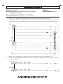
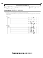
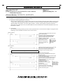
TECHNICAL BULLETIN
[Issue No.] T40-0007
[Title] Corrections in the QnPRHCPU User's Manual
(Redundant System)
[Page] 1/4
[Date of Issue] Dec., '06
[Relevant Models] Q12PRHCPU, Q25PRHCPU
Thank you for your continued support of Mitsubishi programmable logic controllers, MELSEC-Q series.
This bulletin provides information on corrections due to clerical errors in the program examples of the QnPRHCPU User's
Manual (Redundant System) (SH-080486ENG) of “version F (printed in June, 2006)”.
The contents of this technical bulletin are included in the "version G (printed in December, 2006)".
1. Correction
(1)
(2)
(3)
(4)
(5)
Section 7.1 (1) (b) [Diagram 7.2 Example of REMFR instruction programming]
Section 7.3 (1) [Diagram 7.13 Program That Turns on the "USER" LED after System Switching]
Section 8.2 (2) (c) [Diagram 8.10 Sample Program for Clearing Standby System CPU Module Error]
Appendix 4.5 (1) (a) 2) [Diagram App.7 A sample program of CHANGE]
Appendix 5 (2) [Diagram App.20 A program example]
2. Correction details
(1) Section 7.1 (1) (b) [Diagram 7.2 Example of REMFR instruction programming]
The setting condition for the host data link status has been corrected in the example of a program for reading
intelligent function module data of the remote I/O station using the REMFR instruction as shown below.
(Error)
(Correction)
HEAD OFFICE : 1-8-12, OFFICE TOWER Z 14F HARUMI CHUO-KU 104-6212, JAPAN
NAGOYA WORKS : 1-14, YADA-MINAMI 5-CHOME, HIGASHI-KU, NAGOYA, JAPAN
TECHNICAL BULLETIN
[Issue No.] T40-0007
[Title] Corrections in the QnPRHCPU User's Manual
(Redundant System)
[Page] 2/4
[Date of Issue] Dec., '06
[Relevant Models] Q12PRHCPU, Q25PRHCPU
(2) Section 7.3 (1) [Diagram 7.13 Program That Turns on the "USER" LED after System Switching]
The SM1518 contact and the storage destination device of the DMOV instruction have been corrected in the example
of a program for turning ON “USER” LED on the CPU module in the new control system after switching as shown
below.
(Error)
M100
16
END
(Correction)
F2047
F2047
(3) Section 8.2 (2) (c) [Diagram 8.10 Sample Program for Clearing Standby System CPU Module Error]
The SM1510 contact has been corrected in the example of a program for clearing errors of the CPU module in standby
system as shown below.
(Error)
(Correction)
HEAD OFFICE : 1-8-12, OFFICE TOWER Z 14F HARUMI CHUO-KU 104-6212, JAPAN
NAGOYA WORKS : 1-14, YADA-MINAMI 5-CHOME, HIGASHI-KU, NAGOYA, JAPAN
TECHNICAL BULLETIN
[Issue No.] T40-0007
[Title] Corrections in the QnPRHCPU User's Manual
(Redundant System)
[Page] 3/4
[Date of Issue] Dec., '06
[Relevant Models] Q12PRHCPU, Q25PRHCPU
(4) Appendix 4.5 (1) (a) 2) [Diagram App.7 A sample program of CHANGE]
The head device number in the remote register has been corrected in the example of a program when using CC-Link
as shown below.
(Error)
(Correction)
K4X1000
HEAD OFFICE : 1-8-12, OFFICE TOWER Z 14F HARUMI CHUO-KU 104-6212, JAPAN
NAGOYA WORKS : 1-14, YADA-MINAMI 5-CHOME, HIGASHI-KU, NAGOYA, JAPAN
TECHNICAL BULLETIN
[Issue No.] T40-0007
[Title] Corrections in the QnPRHCPU User's Manual
(Redundant System)
[Page] 4/4
[Date of Issue] Dec., '06
[Relevant Models] Q12PRHCPU, Q25PRHCPU
(5) Appendix 5 (2) [Diagram App.20 A program example]
1) Operation of the program before correction
When 32768 seconds (around 9. 1 hours) elapses after the CPU module became RUN status, SD412 value will be
–32768. In the following program (before correction), since the processing is repeated in the relevant program
until the SD412 value will be 10 or more again (around 9. 1 hours), other sequence operations cannot be
performed. Note when this occurs, the CPU module will not be STOP status even the RUN/STOP switch is set
from RUN to STOP.
2) Corrections
The method for starting with the previous control system has been corrected in the example of a program when
mounting a network module to the base unit as shown below.
(Before correction)
Permits system switching after System B's network
unit has started properly.
Executes the system switching instruction after
System B's network unit has started properly.
Jumps to the END instruction during system
switching command execution.
Enables communication with
Program which
GX Developers or others.
waits 10 seconds
Resets the watchdog timer.
while System B's
network module
Jumps to P0 until SD412=10
is starting
(10 seconds).
(After correction)
Makes the subroutine program (P100) execute when
the previous control system is the system B.
Jumps the processing to the END instruction by
executing the system switching instruction.
User program
Ends the main routine program.
Stores the value of SD412 at subroutine program
execution to D400.
Enables system switching when the network module
in the B system starts normally.
Executes the system switching instruction when the
network module in the B system starts normally.
Jumps the processing to P101 with the system
switching instruction.
Enables communications with
GX Developer or others.
Program which
Calculates the subroutine program
waits 10 seconds
executing time.
for the network
Resets the watchdog timer.
module startup
in the system B.
Continues the jumps to P100 until the
SD401 value becomes 10 (10 seconds).
Ends the subroutine program.
HEAD OFFICE : 1-8-12, OFFICE TOWER Z 14F HARUMI CHUO-KU 104-6212, JAPAN
NAGOYA WORKS : 1-14, YADA-MINAMI 5-CHOME, HIGASHI-KU, NAGOYA, JAPAN


![Model Q2AS (H) CPU (S1) User's Manual [1/2]](http://vs1.manualzilla.com/store/data/006867034_1-37d0fc894799b020d67c92be65e419bc-150x150.png)