1
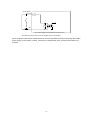
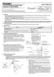
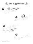
Mitsubishi Motion controller
No. 10-23E
Sales and Service
Correcting the Print on the Marked Tubes of the Forced Stop Input Cable
(Q170DEMICBL M)
Thank you for your continued patronage of the Mitsubishi motion controllers and FA products.
Regarding the forced stop input cable (Q170DEMICBL M), the print on the marked tubes of the cable
differs from that described in the user’s manual. Therefore, we will correct the print on the actual marked
tubes as shown below. The currently used cable can be used without any changes.
Check the following contents, and note the correction when using the forced stop input cable
(Q170DEMICBL M).
We ask for your understanding in this matter.
1. Reasons for Change
The print on the marked tubes of the forced stop input cable differs from that described in the user's
manual.
2. Target Model and Schedule
Product
Forced stop input cable
Cable length
0.5m
1m
3m
5m
10m
15m
20m
25m
30m
Model
Q170DEMICBL05M
Q170DEMICBL1M
Q170DEMICBL3M
Q170DEMICBL5M
Q170DEMICBL10M
Q170DEMICBL15M
Q170DEMICBL20M
Q170DEMICBL25M
Q170DEMICBL30M
Schedule
The print on the actual
marked tubes will be
corrected sequentially from
the October 2010 production.
3. Details of Change
The print on the actual marked tubes will be corrected as shown below.
<Before correction> White cable: "EMI", Black cable: "EMI.COM"
CPU module side
Marked tubes
Crimping terminals
EMI
2
1
EMI.COM
<After correction> White cable: "EMI.COM", Black cable: "EMI"
CPU module side
Marked tubes
Crimping terminals
EMI.COM
2
1
EMI
4. Forced Stop Input Circuit
The forced stop input circuit is configured as shown in the following figure.
Date
of
issue
October
2010
Title
Correcting the Print on the Marked Tubes of Mitsubishi Electric Corp., Nagoya Works
the Forced Stop Input Cable
5-1-14 Yada-minami, Higashi-ku, Nagoya 461-8670
(Q170DEMICBL M)
Tel.: +81 (52) 721-2111 Main line
24VDC (Note)
EMI.COM
R
R
EMI
Forced stop
* The system setting cannot disable the forced stop input.
Note. Both the positive common and the negative common are available.
Since the photocoupler works in both directions, the circuit operates normally even though the 24VDC
power supply is connected in reverse. Therefore, the replacement of the currently used cable is not
required.
-2-