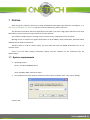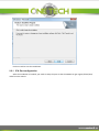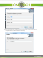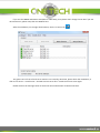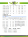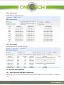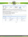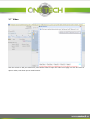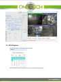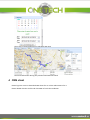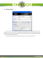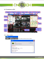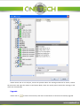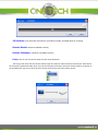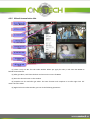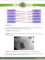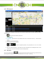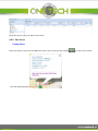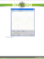
1
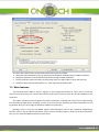
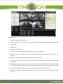
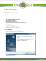
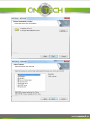
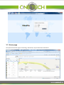
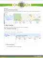
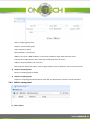
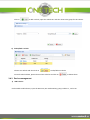
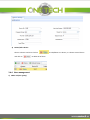
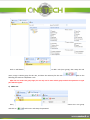
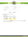
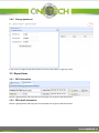
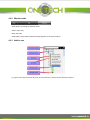
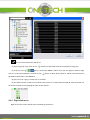
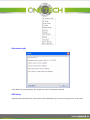
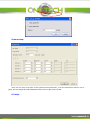
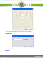
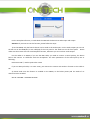
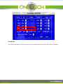
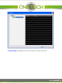
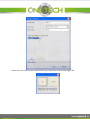
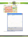
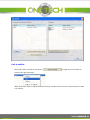
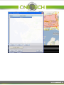
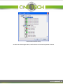
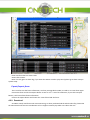
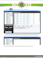
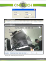
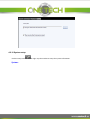
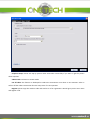
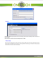
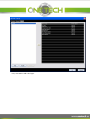
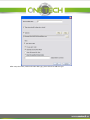
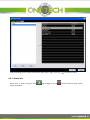
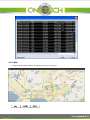
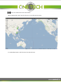
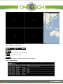
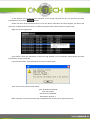
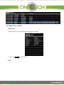
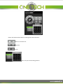
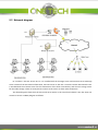
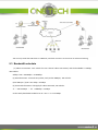
User Manual
For
CMS (WEB version)
NOTICE
The information in this manual was current when published. The manufacturer reserves the right to revise
and improve its products. All specifications are therefore subject to change without any notice.
The purpose of this manual is to kindly aid the user for the MINI MDVR CMS installation and setup.
This CMS installation manual is for S28, X5, A5, F5, X11, X3 and MINI3 module MDVR.
Contents
1
Preface .................................................................................................................................... 1
1.1 System requirements ................................................................................................................ 1
1.2 Main features............................................................................................................................ 2
2
Server Installation .................................................................................................................... 4
2.1 System requirement ................................................................................................................. 4
2.2 Installation ................................................................................................................................ 4
2.2.1 IP & Port configuration ................................................................................................... 6
3
Guide for WCMS ...................................................................................................................... 9
3.1 Supported browser ................................................................................................................... 9
3.2 Login ......................................................................................................................................... 9
3.3 Home page.............................................................................................................................. 10
3.4 Basic function ......................................................................................................................... 11
3.4.1 Company management ................................................................................................ 11
3.4.2 Vehicle management.................................................................................................... 12
3.4.3 Device management .................................................................................................... 13
3.4.4 User management ........................................................................................................ 14
3.4.5 Change password ......................................................................................................... 17
3.5 Report form ............................................................................................................................ 17
3.5.1 GPS information ........................................................................................................... 17
3.5.2 GPS detail information ................................................................................................. 17
3.5.3 Vehicle alarm ................................................................................................................ 18
3.5.4 Over speed ................................................................................................................... 18
3.5.5 User online ................................................................................................................... 19
3.5.6 User details ................................................................................................................... 19
3.6 System management .............................................................................................................. 19
3.6.1 Alarm message and Mail configuration ....................................................................... 19
3.6.2 Alarm message and Mail configuration ....................................................................... 20
3.7 Video ...................................................................................................................................... 21
3.8 GPS Playback........................................................................................................................... 22
4
CMS client.............................................................................................................................. 23
4.1 Network Setup ........................................................................................................................ 24
4.2 Functions on GUI .................................................................................................................... 25
4.2.1 Check version ............................................................................................................... 25
4.2.2 Window mode.............................................................................................................. 26
4.2.3 Vehicle tree .................................................................................................................. 26
4.2.4 Right click menu ........................................................................................................... 27
4.2.5 Video & transmission Info. ........................................................................................... 36
4.2.6 GPS playback ................................................................................................................ 39
4.2.7 Log query...................................................................................................................... 39
4.2.8 Geo fence ..................................................................................................................... 40
4.2.9 Download ..................................................................................................................... 47
4.2.10 System setup............................................................................................................... 50
4.2.11 Alarm Info. .................................................................................................................. 55
4.2.12 Map............................................................................................................................. 56
4.2.13 Vehicle online Info. ..................................................................................................... 58
4.2.14 Log window................................................................................................................. 58
4.2.15 Basic Info. and PTZ ...................................................................................................... 60
5
Case studies ........................................................................................................................... 62
5.1 Introduction ............................................................................................................................ 62
5.2 Network diagram .................................................................................................................... 63
5.3 Bandwidth calculate ............................................................................................................... 64
1 Preface
After you get the software, please try to setup the MDVR and the CMS to get video first according to 3G &
WIFI setup for MDVR28 and CMS3.0. If you don’t have this document, please contact us.
This document introduces the basic application of the CMS. If you have a big project which has more than
100 vehicles, please contact the support team for the best solution.
This software includes 4 parts: message server, transmit server, media proxy server and client.
Message server is used for the register information of all the MDVR, online information, GPS information
and deal with all kinds of commands.
Transmit server is used to transmit video, you must add and setup the MDVR information first in the
transmit server.
Client is for the video display, information display and the reception of the command from the
administrators.
1.1 System requirements
1. Operating System:
Server : windows 2003/2008 server
Client: XP/WIN7 32bit or 64 bit for client
2. The computer must have the drive of DirectX. Please check as follows: Start—Run--input “dxdiag”
Click on “OK”
The Direct Draw Acceleration and Direct3D Acceleration must be enabled.
3. Microsoft .Net Framework 3.5 SP1 or above version should be installed before the CMS installation
4. MySql 5.1 data base will be installed automatically during the CMS installation
5. Please install OCX activeX according to the prompt when you apply video on IE for the first time.
6. IE version: Microsoft Internet Explorer 6.0、Microsoft Internet Explorer 8.0
1.2 Main features
The standard version CMS no need to register, it can manage 100 vehicles on center server of transmit
server. The transmit server can transmit 48 channels concurrently to 3 clients (each has 16 video window) at the
same time.
The CMS is functional which integrate the video transmission, remotely PTZ control, alarm, GPS tracking,
local recording on CMS, alarm recording, and also it can show you the operating and alarm information on the
log window. Also, you can change the interface to different mode easily.
Message server is used for the MDVR register, GPS information and all the commands downloading.
Transmit server is for the video transmission. Client, the user friendly interface, shows you all the information.
Also, you can setup the MDVR remotely from the client.
Main features:
1.
Wireless Video/Audio transmission
2.
GPS tracking: show the real-time location of the vehicle on map window with MapInfo & Google map.
3.
GPS playback
4.
Report query
5.
Support IE browser client.
6.
Send Email to administrator/user automatically once alarm is triggered.
7.
Remotely PTZ control: control the PTZ on CMS, including change direction, pre-set position, call
position.
8.
CMS local recording: record the video from the CMS video window.
9.
Alarm report system: receive the alarm information, and deal with this alarm information according to
the settings.
10. Vehicle management: manage vehicle on the transmit server, show all the vehicle information on the
client vehicle window to check the online information and do some operations remotely to the MDVR.
11. Multi-clients supported: support many clients connect to the server to apply video.
12. Remotely configuration: setup the GPS upload interval, IO setup, stream setup for video transmission
and so on.
2 Server Installation
2.1 System requirement
1. Server: 2003 server, 2008 server
Message and transmit server:
CPU: Quad- Core Xeon 5504*2
RAM: 8GB, ECC DDR3
HDD:2*320GB SAS HDD, 15K RPM Hotplug
Ethernet card: 2* 1000Mbps
2. Client: XP/WIN 7 ( 32bit & 64 bit)
CPU:Dual Core Intel(R) Pentium(R) Processor E5400,2.7GHZ
RAM: 2GB, DDR3
HDD: 320G SATA 7200RPM
Graphics card: NVIDIA GeForce G310
Ethernet card: Integrated 1000 M Ethernet
2.2 Installation
Please double click the exe file to install the server.
Click on Next to continue
Click on Install to start the installation.
2.2.1 IP & Port configuration
After the installation is finished, you need to setup the port so that the WCMS can get register/alarm/GPS/
video from the vehicle.
These ports are the default ports. For 3G transmission, please make sure you have opened these ports:
During the installation, it will read the local IP automatically,
If you test the MDVR and CMS in LAN (WIFI or RJ45 cable), then please don’t change this IP. But if you test
3G transmission, please setup the IP as WAN IP here.
After the installation, on the right down bottom, there is a server icon
.
The green icons in front of each server means it run normally, otherwise, please check the installation, or
click on this server— Install server—uninstall current server first—Install the current server again.
Double click on the message server to check the online information of vehicle and client.
3 Guide for WCMS
3.1 Supported browser
Microsoft Internet Explorer 6.0, 8.0, 9.0.
3.2 Login
You must login the server for the management of vehicle and user. When login, you need to put IP+ port.
If on the server PC, put http://127.0.0.1:7260 in the IE address bar; for remote server, put the IP of PC and
the port like http://58.60.23.1218:7260 Note: “http” here is essential. The default administrator User name and
password is: admin/admin. This user has the authority of managing all vehicles and all users.
3.3 Home page
The layout of the home page is as following, vehicle fleet, map and the alarm information.
Vehicle fleet:
Green means online vehicle without alarm
Red means online vehicle which has alarm
Click on one vehicle to show the real time location of this vehicle, also, the details will be shown below the
vehicle icon
3.4 Basic function
Basic function is for company/group, vehicle, device and user management
3.4.1 Company management
1) Add a company/group
Click on Add button to add a company/group
Name: company/group name
Superior: choose father group
Type: Company or group
Phone Number: not necessary
WAN IP: the server’s WAN IP address, so the client in WAN can apply video from this server.
Transmit Port: 17891 this port is for video out to CMS client from the server.
Address: company address, not necessary
After input the above information, click on Apply button to save to database, click on Cancel to return.
2) Delete a company/group
Choose a company/group to delete.
3) Export a company/group
Export the company/group information to local disk, this information is saved to a excel document.
3.4.2 Vehicle management
1) Add a vehicle
Click on
to add a vehicle, input the vehicle No. and then choose the group for this vehicle.
2) Delete/Edit a vehicle
Choose one vehicle and then click on
to edit/delete a vehicle
For multi vehicle delete, please choose those vehicles and click on
to delete them.
3.4.3 Device management
1) Add a device
Click on Add to add a device, input the Device ID, Sim Card Number, group, vehicle N. , and so on.
2) Delete/Edit a device
Choose a device and then click on
and click on
3.4.4 User management
1) Add a role(user group)
to delete all of them.
to edit/delete one device, or choose several device
Click on add button
to add a role (user group), then setup the role
name, assign a vehicle group for this role, and limit the authority for this role.
following two mark to edit/delete a role.
Click on the
After the user under this group login, he can only see his own vehicle group and do the operations in right
part which is tipped.
2) Add a user
Then,
and click on
choose this user group
to add a user and setup the password.
Click on Apply button to save the user information
3) Delete/Edit a user
Choose on user and click on
delete them after choosing them.
to Edit/Delete a user, for multi user delete, click on
to
3.4.5 Change password
If you want to change the password, please click on the key button in right-top conner.
3.5 Report form
3.5.1 GPS information
Choose a group/vehicle and setup the start time/end time to get the GPS information.
3.5.2 GPS detail information
Choose a group/vehicle and setup the start time/end time to get the GPS information
3.5.3 Vehicle alarm
List out the alarm time/type information
3.5.4 Over speed
3.5.5 User online
Display the user’s login/log out time.
3.5.6 User details
Show you what the user has done after login.
3.6 System management
3.6.1 Alarm message and Mail configuration
This function is for server to send email/short message when certain type alarm information is reported to
server.
Send frequency
Immediately: once server receives IO alarm, send email or SMS to administrator immediately.
O’clock: send the alarm information on clock. For example, you setup it as 8:00:00 ~16:00:00. Then the server
will send all the alarm information between 8 ~9 to administrator at 9 o’clock. The other alarms happened
exceeds this time range won’t be send.
Timing: send all the alarm information to administrator at the setup time.
3.6.2 Alarm message and Mail configuration
Setup the servers sender email account.
3.7 Video
Click the vehicle in left part vehicle list, and choose Video to open the video on IE page. For the first time to
open a video, it will show you to install active X.
3.8 GPS Playback
Click on the vehicle icon and choose GPS playback
Then pull down the bar to setup the start time and end time for GPS route
Then click on Load Tracking Line to playback GPS route
The alarm information during this period will be listed out below.
4 CMS client
Please login the server to download CMS client first or ask the administrator for it.
Please double click the exe file and click NEXT to finish the installation.
4.1 Network Setup
Sever IP is the IP of the PC installed transmit sever, if transmit sever is in LAN with CMS client, the sever IP
should be LAN IP. If you connect to sever via WAN, then the IP should be public IP. If the message server and the
transmit server are on the same PC, and the port is default 5556, then you can tip Default. Otherwise, please
input the message server and port below.
User name and Password: ask the administrator to create for you, and define your authority.
4.2 Functions on GUI
4.2.1 Check version
: click on CMS to check the version number.
4.2.2 Window mode
:
Three button to change to window mode.
Video: video only.
Map: map only.
Video/Map: show video window and map together as the picture above.
4.2.3 Vehicle tree
(1) Type in all or part of vehicle ID, click on search button, it will list all the vehicles matched.
: this is used to refresh the vehicle list.
(2) A3 is the group name, click on this
(3) If the car icon is
button to expand and show all the vehicles in this group.
green, it means this MDVR is online, then you can apply for video or right
click on it to do some operation. And click on the
dns:0000 in the bracket is the MDVR ID.
button to show all the cameras. 11019 is the vehicle name.
(4) If the car icon is gray, it means this car is offline.
(5) The white cameras of the first 3 channels means there is no video data transmitted, while the black one
on the 4th channel means applying for video of this channel.
4.2.4 Right click menu
Right click on the online vehicle to do the following operations:
Get version Info:
If the device has some problem, you can get the version information remotely.
GPS Setup:
Setup the GPS upload interval. If you choose close upload GPS, you cannot see the green icon on the map.
02009: Device ID
Stream setup:
Here you can setup some parts of the upload stream parameters, so if the transmission speed is not so
good, you can change the total bandwidth and the frame to get a better speed.
IO setup:
Setup the IO output of the MDVR remotely, you can control the vehicle remotely.
Mileage setup:
Setup the total mileage of the vehicle.
Intercom:
For the interphone function, it needs both the CMS and the device has audio input and output.
Attention: if you want to use this function, please follow the steps:
1) On the MDVR, only the fourth channel can be used as the audio input. For the audio output you can use
the AV out on the DB44(X11) or AV cable(X3) of the rear panel or the Audio out on the front panel. Please
make sure the monitor has the sound amplifier function, otherwise you can not hear audio output.
For the audio in on MDVR, if you use the BNC cable, you need to connect a sound pick-up, the device
built-in the camera. It is different with the microphone. The main parameters of the sound pick-up are as
following:
Resistance: 600Ω; Peak-to-peak value: 1VPP
If you use DIN-jack cable, it is more easier, just connect the camera with audio in function to this cable is
OK.
2) Please make sure the function is enabled on the MDVR, as the below picture,and the audio of 4th
channel must be enabled.
SETUP—RECORD—CHANNEL SETTING.
Broad cast:
First, choose the vehicle, or select one group to choose all the vehicles, and then click “start” to broadcast.
Send message: the MDVR must connect a control panel to support this function.
Please choose the car on left part, choose the position where this message wanted to be shown, choose
the show time and input the content in the bottom blank, when the control panel receives this message, it will
read it out automatically.
Upgrade:
Please click on
to choose the firmware, and click on Start button to continue the remotely upgrade.
3G dormant: This command will make the 3G module standby, the MDVR keep on recording .
Remote Restart: Restart the MDVR remotely.
Remote Shutdown: shutdown the MDVR remotely.
Listen: click on one channel to listen the voice from the device.
You can get the voice from the device without open the video to reduce the data transmission. And also for
the X11-4CH, X3, MINI3 and D3, when you use the interphone function, the fourth channel will be occupied, so
on the CMS client you can not hear the voice of this channel even open the volume switch.
4.2.5 Video & transmission Info.
(1) There is only one No. for each video window. When you apply for video, it will show the MDVR ID
behind the window No..
(2) After get video, it will show the date and time on the screen of MDVR.
(3) Show the channel name on this window.
(4) Snapshot can be used after get video. The same function with snapshot in list after right click. “X”
means close this video.
(5) Right click on the video window, you can do the following operations:
Close video:
Only close the video, but remain the device ID and Channel No. on this window, so next time you can
choose 5) open video to open this channel video automatically in this window.
Close All: close all the video windows.
Snapshot:get picture of current window. The save path is configured in system setup. Or click on the
camera icon to snapshot
Record: click to record this channel and save to PC. There will be an “R” on right top of this channel.
Note: record means record the video from the CMS, and save path is the one setup in system. And once
the network disconnect, it will pack; otherwise pack it every 30 minutes.
Open video: only available when close one channel.
Open all: click to open all closed channels
Clear Data:
clear all the data of the window you choose, shown as the blow picture, no channel
information stays in this window.
Clear all the data: clear all the data of all the current open windows.
Scale: 3 options: default is fulfill the screen; 4:3; 16:9
Full screen: Full screen this channel.
(6) Get video info.
: Green means the CMS is receiving video now.
: can not get video.
VOLT: voltage of the power input.
Frame: the frame in the buffer.
SIZE: data package received now.
(7) Volume and window
:
Click
this icon to turn on/ turn off the audio. CMS can only play one channel audio currently by click
on the video window.
Click
to change the window number.
(8) Page up and down button
Page up/ page down
4.2.6 GPS playback
GPS playback is playback the GPS route of this vehicle of specified time slot. Please follow the steps to
playback:
1.
Click on this icon to choose a device first.
2.
The red dot on the calendar means there is GPS data at that day.
Choose the data
please.
3. Setup the start time and end time
4. Click on search to get the GPS data
5.
Buttons for playback operation: slow, pause/start, fast. X5 is the current
speed.
6. This is for alarm information. It will load all the alarm information when loading GPS data. You can
double click on the alarm information to locate the GPS position.
4.2.7 Log query
Click on the log query button
on right top of the main interface to check the log. It will link to the IE,
please login the IE using your own User name and password. Go to report—system log
Setup the source, type, user and time to search.
4.2.8 Geo fence
Create fence:
There two ways to enter into the GEO fence setup. Click on the Geo fence button
icon and choose GEO fence
.
, or click on the vehicle
Click on Create button,
Please enter into the Fence name, choose alarm type, setup alarm name and the trigger time.
Click on OK button, the fence will be shown on the list.
Link to vehicle:
Choose this fence and click on the button
or right click on this fence to
setup on the right click menu.
When choose this fence, it will be shown on the map, and then click on Link to a vehicle button, to bind
it to vehicles.
Click on OK to finish the setup.
So when the vehicle triggers alarm, it will be shown on the alarm log window as below.
Enter into fence alarm is alarm name.
Ge02 is fence name.
Note: this only gives an alarm log, if you want the CMS to record or play sound, please go to alarm setup in
system setup.
Export/Import fence:
This is used to save the fence information, so when you upgrade the CMS, no need to re-create them again.
Choose the fence and click on Export button to save it as a **.areas file. Otherwise, if you click on Export
button, it will save all the fences information.
Click on the Import button and choose the .areas file to load the fence.
4.2.9 Download
As CMS is mainly used for 3G real-time monitoring, so when you download the whole video file, please take
the 3G network and cost into consideration. Also it support remotely clip which can reduce the cost.
Click on the
download icon on right top of the main interface.
First choose an online device, setup the date, time, channel and file type to search. It will list all the files.
Then select one and click on download. And click on the download label to check the details information.
If you want to clip part of the file, click on Clip button to setup the start time and end time.
After download the video, you can easily check the video using playback function.
Setup the path: click on config label to setup save path.
4.2.10 System setup
Click the setup icon
System:
on right- top the window to setup the system information.
Snapshot Setup: Please tick Pop-up picture when Screenshot successfully if you want to get the picture
when snapshot.
Video mode: real-time or smooth mode
Cut off video: this function is developed to reduce the transmission cost when no one monitors video. It
will cut off the video transmission after the setup mins if no one operates.
Register: please copy the machine code and send it to us for registration. We will give you the user name
and register code.
Record:
Record Save Path: setup the disk for the local recording, and the alarm recording on CMS. The folder will
be in each disk.
Note: This path is used for the local recording function on CMS.
Alarm setup:
After setup the dealing type for each event here, when the CMS receive the alarm information from the
device (alarm information will be shown on the Log window—Alarm Log), it will make a sound, pop-up
video window and record video automatically.
First, click Add to add a deal type.
After setup the name, audio and video deal type, pleas click OK to add this type
Click the dealing type in the left and then the alarm type in right, then click
to setup the alarm.
4.2.11 Alarm Info.
When there is alarm, the green icon
alarm information.
will change to be red
. Click red icon to check all the
4.2.12 Map
In Map and Video/Map window, the Maximize button can be used.
: this one is used to full screen the window
When in Map mode, then if you click this icon, it only full screen the map.
If in Video/Map mode, it will full screen the video and map.
4.2.13 Vehicle online Info.
: This is the total number of device
: Currently online number.
: the number of vehicle which has GPS info. reported.
4.2.14 Log window
In this window, you can see all your operation on the system log. And also you can check all the alarm
information by click on the
button.
Please note that alarm information here is from the device, whenever the alarm happens, the device will
report this to CMS and be shown here. It is different with the alarm filter function in system setup.
Right click on the log window,
Scroll means: when the information is full of the log window, it can scroll down automatically, the latest
information is shown on the top.
Copy the information: copy information to paste it to other place.
Then use Ctrl+V to paste the information.
Time: 2010-05-13 12:28:18
Type: Close video
Device ID: dns:SZGJ0002
Information: Channel: 1
When snapshot, it will show you the path, and double click on this path to open the picture.
4.2.15 Basic Info. and PTZ
Basic Info.:
Click the online car, it will show you the information as follows:
Click this icon
PTZ:
to hide this part.
Please click the directional button to change the camera direction.
: Zoom in and zoom out.
: Aperture
: Focus
: This is for pre-set and calling position.
5 Case studies
5.1 Introduction
There are two typical cases: the first one need to transmit about 250 channels video all the time, so the PC
and network must very good to match this requirement; the second one have 1000 MDVRs, but no need to
transmit so many channels concurrently, so it is more easier compared with the first one.
CMS can support 2000 MDVRs at the same time, and it would be a little slow and refreshes every 15~20
seconds.
And if you want to get more channels at the same time, please take the 3G signal strength, bandwidth and
PC performance into consideration.
Here I will give you two examples:
(1) Project reference 1: UNINET
In this project, there are 325 vehicles, and almost 250 MDVRs' video need to be checked concurrently.
All the online vehicles report the online, GPS, and alarm information back to CMS message server.
Due to the limitation of the PC memory, 2 transmit servers are required for the video transmission. (4GB
memory can transmit less than 200 channels)
Due to the limitation of the 3G bandwidth, it won't be possible for the mass data transmission, our
experience with UNINET project (one of the biggest telecommunications operators).
In this project, 30 CMS clients are used for video live view checking. Each client has 16 video windows
because of the limitation of the PC graphics card.
(2) Project reference 2: public bus
In this project, 1000 vehicles report GPS, online and alarm information back to CMS message server.
Since there are not as much live video transmission as UNIET project, only one transmit server is
required for video transmission and 10 clients for video checking.
Conclusion:
(1) For live viewing, due to the limitation of the PC graphic card, you can only view 16 channels
concurrently per PC.
(2) For video transmission, due to the limitation of the PC memory, one PC can transmit less than 200
channels at the same time.
5.2 Network diagram
PC 1 and PC 2 are two servers PC. PC 1 is installed with the message server and transmit server. Message
server receive all the 325 vehicle information, transmit server on the PC1 is used to transmit 200 channels. PC2
is installed with the transmit server for the transmission of the other 125 vehicles, and also has storage server
for the video storage. There are many clients connect to the server to check video all the time.
The above diagram shows that the client and server works in the same local network. Also the client can
connect to server via WAN, diagram as follows:
You can only install the CMS client in a WAN PC, and then connect it to the server to realize monitoring.
5.3 Bandwidth calculate
(1) Video transmission: each vehicle has one channel video transmitted, and the bandwidth is 50Kbps,
325 vehicles.
50kbps *325 = 16250Kbps = 15.87Mbps
(2) GPS information: 5 seconds one packet, each packet 200Bytes, 325 vehicles.
(325*200 Byte / 5)*8 = 101.7kbps = 0.1Mbps
(3) Command information: like apply for video command, 325 vehicles.
2*((325*256 Byte )*8)=1300Kbps = 1.3Mbps
So the totally bandwidth needed is 15.87 + 0.1 + 1.3 = 17.27Mbps.