1
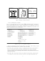
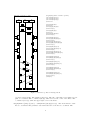
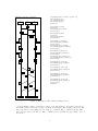
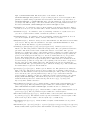
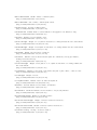
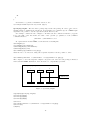
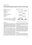
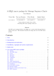
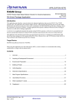
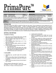
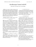
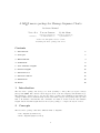
A LATEX macro package for Message Sequence Charts
Reference Manual
Victor Bos
Ton van Deursen
Sjouke Mauw
[email protected]
Université du Luxembourg
[email protected]
Université du Luxembourg
[email protected]
Version 1.17, last update October 1, 2012
Describing msc macro package version 1.17
Contents
1 Introduction
1
2 Concepts
1
3 Environments
3
4 Commands
6
5 User definable lengths
13
6 lnternal lengths
15
7 Internal boxes
15
8 Internal counters
15
9 Limitations
16
10 Tricks
16
1
Introduction
The msc macro package was developed to draw (actually, to write) Message Sequence Charts
(mscs) with LATEX. The current version supports most of the msc language standardized in [2].
The manual [1] describes how to use the msc macro package and is illustrated with numerous
examples. This reference manual briefly describes the main concepts of the package and it provides
lists of all available environments and commands. In addition, it lists both the user-definable
lengths and the internal lengths that are used by the package to compute the layout of mscs.
2
Concepts
The msc macro package offers three different kinds of diagrams:
• msc diagrams (normal mscs)
• hmsc diagrams (high level mscs)
1
hmsc Example 2
msc Example 1
i
mscdoc Example 3
j
A
a
A
b
?
B
C
(a) msc diagram
(b) hmsc diagram
(c) mscdoc diagram
Figure 1: Examples of different diagrams
• mscdoc diagrams (msc documents)
For each of these diagrams, the package provides a LATEX environment. Figure 1 shows an example of each diagram. The source code for these diagrams is given in Figure 2. Depending on
the environment, different msc macro package commands can be used. Furthermore, since each
environment is implemented as a pspicture (see pstricks documentation), it is possible to use
pstricks commands inside the msc environments.
\begin{msc}%
{Example 1}
\declinst{i}{$i$}{}
\declinst{j}{$j$}{}
\nextlevel
\mess{a}{i}{j}
\nextlevel[2]
\mess{b}{j}{i}
\nextlevel
\end{msc}
\begin{hmsc}%
{Example 2}%
(0,0)(4,4.65)
\hmscstartsymbol{S}(2,3.75)
\hmscconnection{c}(2,3.25)
\hmscreference{R1}{A}(2,2.5)
\hmsccondition{C}{?}(2,1.5)
\hmscendsymbol{E}(1.5,0.5)
\arrow{S}{c}
\arrow{c}{R1}
\arrow{R1}{C}
\arrow{C}
[(2.5,1)(3,1)(3,3.25)]
{c}
\arrow{C}[(1.5,1)]{E}
\end{hmsc}
\begin{mscdoc}%
{Example 3}%
(0,0)(4,4.65)
\reference{A}(1,3.0)
\reference{B}(3,3.0 )
\separator{2.0}
\reference{C}(2,1.0)
\end{mscdoc}
Figure 2: Source code for diagrams of Figure 1
The msc environment provides most functionality of the package. The following concepts
should help in understanding the user-commands of this environment.
current height The current height of an msc is a length that indicates the y-postion relative to
the top of the msc frame. The msc drawing commands use this y-position to draw msc
symbols, e.g., instance heads, messages, actions, and instance feet. The internal length
\msc@currentheight is the current height. This variables is changed whenever the command
\nextlevel is invoked.
current width The current width of an msc is the distance from the left side of the msc frame
to the right side of the msc frame. As such, it depends on the lengths \envinstdist and
2
\instdist as well as on the number of instances. The internal length \msc@currentwidth is
the current width. During construction of an msc, that is, in between \begin{msc} and
\end{msc}, \msc@currentwidth is equal to \envinstdist + (n × instdist), provided that n
is the number of instances defined so far (see \mscinstcnt in the section Internal counters
below) and the length \instdist is not changed between instances. At the end of an msc
construction, an additional \envinstdist is added to \msc@currentwidth. The
\msc@currentwidth determines the x-position of new msc instances.
level A level is a horizontal layer in an msc which is used to construct msc’s in a top-down
fashion. Each level is \levelheight units high and spans the complete width of the msc. The
first level starts at \topheaddist + \instheadheight + \firstlevelheight units below the
top of the msc frame. The \nextlevel commands advances the msc to the next (lower) level.
msc instance The main building blocks of MSC diagrams are instances. Instances are
represented by vertical bars. Fat instances are represented by two vertical lines. Usually, an
instance has both a head symbol and a foot symbol. In the msc macro package, each msc
instance has a nickname by which the instance is identified. In the msc macro package there
are special instances:
•
The left environment (nickname envleft).
•
The right environment (nickname envright).
•
The left side of an inline expression. If the nickname of the inline expression is nm, the
nickname of the left side is nmleft.
•
The right side of an inline expression. If the nickname of the inline expression is nm, the
nickname of the left side is nmright.
•
The left side of an reference expression. If the nickname of the reference expression is nm,
the nickname of the left side is nmleft.
•
The right side of an reference expression. If the nickname of the reference expression is
nm, the nickname of the left side is nmright.
•
A dummy instance is an instance that is invisible; it reserves space needed to draw an
instance. It is useful to create (see create command) instances with create-messages.
nickname
A nickname is a unique identification of an instance.
message label reference points In order to place a message label somewhere near the message
arrow, the msc macro package computes a reference point for each message label. This is a
location on the bounding box of the label such that the distance between the arrow and the
reference point is minimized. Figures 3 (page 4) and 4 (page 5) show the location of reference
points for all possible locations of message labels. Note that the boxes with the location of the
reference points are not generated by the LATEX code given in these figures; we enriched the
LATEX code with some extra pstricks code (see LATEX source code of this document).
3
Environments
\begin{msc}[titlepos]{title}...\end{msc} The environment to draw msc’s. The parameter
title defines the title of the msc. The optional parameter titlepos defines the position of the
title relative to the frame of the msc. Valid positions are l (left), c (center), and r (right).
The default position is l.
\begin{hmsc}[titlepos]{title}...\end{hmsc}(llx,lly)(urx,ury) The environment to draw
hmsc’s. The parameter title defines the title of the hmsc. The optional parameter titlepos
defines the position of the title relative to the frame of the hmsc. Valid positions are l (left),
3
msc Label reference points
I0
I1
\begin{msc}{Label reference points}
\declinst{m0}{I0}{}
\declinst{m1}{I1}{}
\declinst{m2}{I2}{}
\nextlevel
I2
\mess{S}{m0}{m1}
\nextlevel
\mess{N}[b]{m1}{m2}
\nextlevel[2]
s
n
s
\mess{S}{m1}{m0}
\nextlevel
\mess{N}[b]{m2}{m1}
\nextlevel[2]
n
e
w
w
\mess{E}{m0}{m0}[2]
\mess[r]{W}{m2}{m2}[2]
\nextlevel[4]
\mess{W}[r]{m0}{m0}[2]
\mess[r]{E}[l]{m2}{m2}[2]
\nextlevel[6]
e
e
\mess{E}{m0}{m0}[-2]
\mess[r]{W}{m2}{m2}[-2]
\nextlevel[4]
\mess{W}[r]{m0}{m0}[-2]
\mess[r]{E}[l]{m2}{m2}[-2]
\nextlevel[2]
w
w
e
\mess{SW}{m0}{m1}[2]
\mess{NE}[b]{m1}{m2}[2]
\nextlevel[6]
sw
\mess{SW}{m1}{m0}[-2]
\mess{NE}[b]{m2}{m1}[-2]
\nextlevel[2]
ne
\mess{SE}{m1}{m0}[2]
\mess{NW}[b]{m2}{m1}[2]
\nextlevel[6]
sw
ne
\mess{SE}{m0}{m1}[-2]
\mess{NW}[b]{m1}{m2}[-2]
\nextlevel[2]
\end{msc}
se
nw
se
nw
Figure 3: Reference points of message labels
c (center), and r (right). The default position is l. The size of the hmsc is determined by two
pairs of coordinates. The coordinates (llx,lly) define the lower left corner of the hmsc. The
coordinates (urx,ury) define the upper right corner of the hmsc.
\begin{mscdoc}[titlepos]{title}...\end{mscdoc}(llx,lly)(urx,ury) The environment to draw
mscdoc documents. The parameter title defines the title of the mscdoc document. The
4
msc Label reference points (2)
I0
I1
\begin{msc}{Label reference points (2)}
\declinst{m0}{I0}{}
\declinst{m1}{I1}{}
\declinst{m2}{I2}{}
\nextlevel
I2
\mess{S}{m0}[.9]{m1}
\nextlevel
\mess{N}[b]{m1}[.9]{m2}
\nextlevel[2]
s
n
s
\mess{S}{m1}[.9]{m0}
\nextlevel
\mess{N}[b]{m2}{m1}
\nextlevel[2]
n
e
\mess{E}{m0}[.9]{m0}[2]
\mess[r]{W}{m2}[.9]{m2}[2]
\nextlevel[4]
\mess{W}[r]{m0}[.9]{m0}[2]
\mess[r]{E}[l]{m2}[.9]{m2}[2]
\nextlevel[6]
w
w
e
e
\mess{E}{m0}[.9]{m0}[-2]
\mess[r]{W}{m2}[.9]{m2}[-2]
\nextlevel[4]
\mess{W}[r]{m0}[.9]{m0}[-2]
\mess[r]{E}[l]{m2}[.9]{m2}[-2]
\nextlevel[2]
w
w
e
\mess{SW}{m0}[.9]{m1}[2]
\mess{NE}[b]{m1}[.9]{m2}[2]
\nextlevel[6]
\mess{SW}{m1}[.9]{m0}[-2]
\mess{NE}[b]{m2}[.9]{m1}[-2]
\nextlevel[2]
sw
ne
sw
\mess{SE}{m1}[.9]{m0}[2]
\mess{NW}[b]{m2}[.9]{m1}[2]
\nextlevel[6]
ne
\mess{SE}{m0}[.9]{m1}[-2]
\mess{NW}[b]{m1}[.9]{m2}[-2]
\nextlevel[2]
\end{msc}
se
nw
se
nw
Figure 4: Reference points of shifted message labels
optional parameter titlepos defines the position of the title relative to the frame of the mscdoc
document. Valid positions are l (left), c (center), and r (right). The default position is l. The
size of the mscdoc is determined by two pairs of coordinates. The coordinates (llx,lly) define
the lower left corner of the mscdoc. The coordinates (urx,ury) define the upper right corner of
the mscdoc.
5
4
Commands
\action(*){txt}{nm} Draws an action symbol on the instance with nickname nm. The
parameter txt defines the name of the action. The size of the action symbol is controlled by
the \actionheight and \actionwidth lengths. The starred version expands the action
symbol based on the size of the contents.
\arrow(*){nm0 }[(xpos1 ,ypos1 ). . .(xposn ,yposn )]{nm1 } Draws an arrow in an hmsc diagram.
The arrow starts at the symbol with nickname nm0 and ends at the symbol with
nickname nm1. The optional parameter (xpos1 ,ypos1 ). . .(xposn ,yposn ) is a list of intermediate
points the arrow should pass through. The stared version draw a line, instead of an arrow.
\changeinstbarwidth{nm}{wd } Changes the bar width of instance nm to wd. The parameter
wd should be a valid LATEX length.
\msccomment[pos]{txt}{nm}[offset] Puts a comment at instance nm. The parameter txt is the
comment. The optional parameter pos defines the horizontal position of the comment relative
to instance nm. Valid positions are l (left), r (right), and all valid lengths. If the position is l
or r, the comment will be put at \msccommentdist units to the left or right, respectively, from
the instance axis. If pos is a length, the comment will be put pos units from the instance axis.
A negative pos puts the comment to the left and a positive pos puts it to the right of the
instance axis. The second optional parameter offset defines the y-position of the comment’s
box relative to starting point of the comment. The relative y-position is defined by
\msc@currentheight + (offset × \levelheight).
\condition(*){txt}{instancelist} Draws a condition symbol on the instances occurring in
instancelist. The parameter txt defines the text to be placed in the condition symbol. The
parameter instancelist is a comma separated list of instance nicknames. Note that there
should be no white space between the commas and the nicknames; only if a nickname contains
white space is a white space allowed in instancelist. The starred version expands the action
symbol based on the size of the contents.
\coregionend{nm}
\regionend).
Ends the co-region on the instance nm. This command is obsolete (see
\coregionstart{nm}
\regionstart).
Starts a co-region on the instance nm. This command is obsolete (see
\create(*){msg}[labelpos]{creator }[placement]{nm}[width]{na}[head height]{in}[foot height]
Creates the instance with label nm. If creator is specified, a message with label msg is sent
from instance creator to instance nm. Instance nm should be a dummy (invisible) instance at
the time of the create message, see \dummyinst. The starred version draw a dashed line
instead of a solid line. The head symbol of nm is drawn at \msc@currentheight. The
parameter an (above name) is put above the head symbol. The parameter in (inside name) is
put inside the head symbol. nm’s y-position is set to \msc@currentheight +
\instheadheight. The optional parameter labelpos defines the position of the message label.
Valid values are t and b, denoting a label position on top of the arrow and a label position
below the arrow, respectively. The optional parameter placement defines the relative position
of the message label along the message arrow. Valid values are real numbers in the closed
interval [0, 1], where 0 corresponds to the beginning of the arrow and 1 corresponds to the end
of the arrow. The default value is 0.5. The optionals parameters width, head height and foot
height customize the shape of the created intance. If the optionals parameters aren’t set the
values \instwidth, \instheadheight and \instfootheight are used.
\declinst(*)[width]{nm}[head height]{an}[foot height]{in} Defines an instance with
nickname nm. The starred version makes a fat instance. The x-position is \instdist to the
6
right of \msc@currentwidth. The head symbol of the instance is drawn at
\msc@currentheight. The parameter an (above name) is put above the head symbol. The
parameter in (inside name) is put inside the head symbol. The instance y-position is set to
\msc@currentheight + \instheadheight. The optionals parameters width, head height and
foot height customize the shape of the created intance.If the optionals parameters aren’t set
the values \instwidth, \instheadheight and \instfootheight are used.
\drawframe{str } A command to turn on/off the drawing of the frame around msc’s, hmsc’s,
and mscdoc’s. If str is ‘yes’, the frame will be drawn, otherwise the frame will not be drawn.
\drawinstfoot{str } A command to turn on/off drawing of instance foot symbols. If str is
‘yes’, the foot symbols will be drawn, otherwise they will not be drawn.
\drawinsthead{str } A command to turn on/off drawing of instance head symbols. If str is
‘yes’, the head symbols will be drawn, otherwise they will not be drawn.
\dummyinst(*){nm} Defines a dummy instance with nickname nm. The starred version makes
a fat instance. The x-position is \instdist to the right of \msc@currentwidth. No head
symbol is drawn. The instance y-position is undefined.
\found(*)[pos]{label }[labelpos]{gate}[offset]{nm}[placement] Draws a found message to
instance nm. The label parameter defines the message name. The gate parameter defines the
gate name. The starred version draw a dashed line instead of a solid line. The optional
parameter pos defines the position of the message relative to instance nm. Valid positions are
l (left) and r (right). The default position is l. The optional parameter labelpos defines the
position of the message label with respect to the arrow. Valid values are t (on top) and b
(below). The default value is t. The optional parameter placement defines the relative
position of the message label along the message arrow. Valid values are real numbers in the
closed interval [0, 1], where 0 corresponds to the beginning of the arrow and 1 corresponds to
the end of the arrow. The default value is 0.5. The length of the arrow is determined by
\selfmesswidth. The optional parameter offset defines the message slope. The default value
is 0. Valid values for offset are all real numbers.
\gate(*)[hpos][vpos]{txt}{nm} Draws a gate at instance nm. The parameter txt defines the
name of the gate. The starred version produces a visible gate by drawing a black circle at
instance nm. The unstarred version produces an invisible gate. The position of the parameter
txt is controlled by the optional parameters hpos and vpos: hpos defines the horizontal
position relative to instance nm and vpos defines the vertical position relative to the current
height (\msc@currentheight). Valid horizontal positions are l (left) and r (right). The
default horizontal position is l. Valid vertical positions are t (top), c (center), and
b (bottom). The default vertical is t.
\hmsccomment{nm}{txt}(xpos,ypos) Draws an hmsc comment symbol with nickname nm at
position (xpos,ypos). The txt parameter is placed inside the comment symbol. The leghts
\hmsccommentwidth and \hmsccommentheight determine the size of comment box.
\hmsccondition{nm}{txt}(xpos,ypos) Draws an hmsc condition symbol with nickname nm at
position (xpos,ypos). The txt parameter is placed inside the condition symbol.
\hmscconnection(*){nm}(xpos,ypos) Draws an hmsc connection symbol with nickname nm
at position (xpos,ypos). The unstarred version produces an invisible connection symbol. The
starred version produces a visible connection symbol (i.e., a small circle).
\hmscendsymol{nm}(xpos,ypos)
(xpos,ypos).
Draws an hmsc end symbol with nickname nm at position
\hmscinlinel[vert. separators]{nm}[hor. separators]{txt}(xposstart,yposstart)(xposend,yposend )
Draws an hmsc inline expresion symbol with nickname nm with upper left corner at position
7
(xposstart,yposstart) and bottom right corner at position (xposend,yposend ). The txt is placed
in the upper left corner of the rectangle.
\hmsckeyword
The hmsc keyword. The default value is ‘hmsc’.
\hmsckeywordstyle{kw } A one-parameter command to typeset the hmsc keyword. The
command can expect \hmsckeyword to be the value of kw. The default ‘value’ is \textbf.
\hmscreference{nm}{txt}(xpos,ypos) Draws an hmsc reference symbol with nickname nm at
position (xpos,ypos). The txt parameter is placed inside the condition symbol.
\hmscstartsymbol{nm}(xpos,ypos) hmsc start symbol with nickname nm at position
(xpos,ypos).
\inlineend(*){nm} Ends the matching inline expression (matching means equal nicknames).
The unstarred version draws a solid line to close the inline expression. The starred version
draws a dashed line to close the inline expression.
\inlineseparator{nm} Draws an inline separator line at the inline expression with nickname
nm. The separator is drawn at \msc@currentheight.
\inlinestart[lo][ro]{nm}{txt}{fi }{li } Defines an inline expression with nickname nm. The
inline expression is started at \msc@currentheight and continues until the level where a
matching \inlineend command is found (matching means equal nicknames). The txt
parameter defines the text of the inline expression. The first instance of the inline expression
is fi. The last instance of the inline expression is li. The optional parameter lo defines the left
and right overlap of the inline expression. If the second optional parameter, ro, is present, lo
defines the left and ro defines the right overlap.
\inststart[width]{nm}[head height]{an}[foot height]{in} Starts instance with nickname nm.
Instance nm should be a dummy (invisible) instance at the time of the \inststart command,
see \dummyinst. The head symbol is drawn at \msc@currentheight. The parameter an
(above name) is put above the head symbol. The parameter in (inside name) is put inside the
head symbol. The instance y-position is set to \msc@currentheight + \instheadheight.The
optionals parameters width, head height and foot height customize the shape of the created
intance. If the optionals parameters aren’t set the values \instwidth, \instheadheight and
\instfootheight are used.
\inststop{nm} Stops instance with nickname nm. The foot symbol is drawn at
\msc@currentheight. The instance y-position is undefined after this command.
\lost(*)[pos]{label }[labelpos]{gate}[offset]{nm}[placement] Draws a lost message from
instance nm. The label parameter defines the message name. The gate parameter defines the
gate name. The starred version draw a dashed line instead of a solid line. The optional
parameter pos defines the position of the message relative to instance nm. Valid positions are
l (left) and r (right). The default position is l. The optional parameter labelpos defines the
position of the message label with respect to the arrow. Valid values are t (on top) and b
(below). The default value is t. The optional parameter placement defines the relative
position of the message label along the message arrow. Valid values are real numbers in the
closed interval [0, 1], where 0 corresponds to the beginning of the arrow and 1 corresponds to
the end of the arrow. The default value is 0.5. The length of the arrow is determined by
\selfmesswidth. The optional parameter offset defines the message slope. The default value
is 0. Valid values for offset are all real numbers.
\measure(*)[pos]{txt}{nm1 }{nm2 }[offset][instance offset] Puts a measure at instances nm1
and nm2. The parameter txt defines the label of the measure. The starred version puts the
triangular measure symbols outside the measure; the unstarred version puts the triangular
8
measure symbols inside the measure. The optional pos parameter defines the horizontal
position of the measure relative to instances nm1 and nm2. Valid positions are l (left),
r (right), and all valid lengths. If the position is l or r, the measure will be put at
\measuredist units to the left or right, respectively, from the closest instance axis. If pos is a
length, the measure will be put pos units from the closest instance axis. A negative pos puts
the measure to the left and a positive pos puts it to the right of the instances. The optional
parameter offset defines the number of levels the measure should extend vertically. The
default value for offset is 1. Valid values for offset are all real numbers. The optional
parameter instance offset can correct false computation of end point x-position. The default
value is 0 and value can be expressed in any terms of length.
\directedmeasure[pos]{txt}{nm1 }{nm2 }[offset][instance offset]
measure except the top arrow isn’t drawn.
This command is the same as
\measureend(*)[pos]{txt}{nm}{gate} Puts a measure end symbol at instance nm. The
starred version puts the triangular measure symbol outside the measure; the unstarred version
puts the triangular measure symbol inside the measure. The txt parameter defines the label of
the measure. The gate parameter defines the name of the gate of the measure end symbol.
The optional pos parameter defines the horizontal position of the measure relative to the nm
instance. Valid positions are l (left), r (right), and all valid lengths. If the position is l or r,
the measure will be put at \measuredist units to the left or right, respectively, from the
instance axis. If pos is a length, the measure will be put pos units from the instance axis. A
negative pos puts the measure to the left and a positive pos puts it to the right of the instance.
\measurestart(*)[pos]{txt}{nm}{gate} Puts a measure start symbol at instance nm.The
starred version puts the triangular measure symbol outside the measure; the unstarred version
puts the triangular measure symbol inside the measure. The txt parameter defines the label of
the measure. The gate parameter defines the name of the gate of the measure start symbol.
The optional parameter pos defines the horizontal position of the measure relative to instance
nm. Valid positions are l (left), r (right), and all valid lengths. If the position is l or r, the
measure will be put at \measuredist units to the left or right, respectively, from the instance
axis. If pos is a length, the measure will be put pos units from the instance axis. A negative
pos puts the measure to the left and a positive pos puts it to the right of the instance.
\mess(*)[pos]{label }[labelpos]{sender }[placement]{receiver }[offset][instance offset] Draws a
message from sender instance to receiver instance. The starred version draws a dashed line
arrow, instead of a solid arrow. This can be used to distinguish method calls from method
replies. The sender and receiver may be the same instance, in which case the message is a self
message. The parameter label defines the message name. The message starting y-position is
\msc@currentheight and the ending y-position of the message is defined by
\msc@currentheight + (offset × \levelheight). The optional parameter pos defines the
position of self messages with respect to the instance axis. Valid values are l (left) and r
(right). The default value is l. The optional parameter labelpos defines the position of the
message label. In case of a self message, valid values are l and r, denoting a label position left
from the arrow and right from the arrow, respectively. For self-messages the default value of
labelpos is the value of pos. In case of a non-self message, valid values are t (default) and b,
denoting a label position on top of the message arrow and below the message arrow,
respectively. The optional parameter placement defines the relative position of the message
label along the message arrow. Valid values are real numbers in the closed interval [0, 1],
where 0 corresponds to the beginning of the arrow and 1 corresponds to the end of the arrow.
The default value is 0.5. The default value of the optional parameter offset is 0 for normal
messages and 1 for self messages. Valid values for offset are all real numbers. The optional
parameter instance offset can correct false computation of end point x-position. The default
value is 0 and value can be expressed in any terms of length
9
\messarrowscale{scalefactor }
The default value is 1.5
Sets the scale factor (a real number) of message arrow heads.
\mscdate The date of the msc macro package.
\mscdockeyword The mscdoc keyword. The default value is ‘mscdoc’.
\mscdockeywordstyle{kw } A one-parameter command to typeset the mscdoc keyword. The
command can expect \mscdockeyword to be the value of kw. The default ‘value’ is \textbf.
\msckeyword The msc keyword. The default value is ‘msc’.
\msckeywordstyle{kw } A one-parameter command to typeset the msc keyword. The
command can expect \msckeyword to be the value of kw. The default ‘value’ is \textbf.
\mscmark[pos]{txt}{nm} Puts a mark at instance nm. The parameter txt is the name of the
mark. The optional parameter pos defines the horizontal and vertical position of the mark
relative to instance nm and the current height \msc@currentheight. Valid positions are
tl (top-left), tr (top-right), bl (bottom-left), and br (bottom-right). The default position is
tl. The horizontal distance between the mark and the instance is defined by \selfmesswidth
and vertical distance by \markdist.
\mscunit A string denoting the (default) unit of all lengths used by the msc macro package.
Valid values are cm, em, ex, in, mm, pt, etc. The default value is cm.
\naction(*){txt}{nm} Draws an action symbol with a cross on the instance with nickname
nm. The parameter txt defines the name of the action. The size of the action symbol is
controlled by the \actionheight and \actionwidth lengths. The starred version expands the
action symbol based on the size of the contents.
\ncondition(*){txt}{instancelist} Draws a condition symbol with a cross on the instances
occurring in instancelist. The parameter txt defines the text to be placed in the condition
symbol. The parameter instancelist is a comma separated list of instance nicknames. Note
that there should be no white space between the commas and the nicknames; only if a
nickname contains white space is a white space allowed in instancelist. The starred version
expands the action symbol based on the size of the contents.
\setmscunit{unit} Changes the value of \mscunit into unit. Valid values for unit are cm, em,
ex, in, mm, pt, etc.
\mscversion
The version number of the msc macro package.
\ncondition(*){txt}{instancelist} Draws a crossed-out condition. Its functionality is
otherwise equal to the condition command.
\nextlevel[offset] Increases the number of levels by the value of the optional parameter offset.
Valid values for offset are all real numbers. The default value of offset is 1. Increasing the
level number means that \msc@currentheight is increased by offset × \levelheight. The
first time this macro is used, the actual increase of \msc@currentheight is
\firstlevelheight + ((offset − 1) × \levelheight). Negative values of offset back up a
number of levels. There are situations where this is useful, see Section 10.
\nogrid Turns off grid drawing in msc, hmsc, and mscdoc diagrams. This command should
not be used inside an msc, hmsc, or mscdoc evironment.
\order(*)[pos]{sender }{receiver }[offset][instance offset] Draws an order line from the sender
instance to the receiver instance. The starred version draw a line instead of an arrow. The
sender and receiver may be the same instance, in which case the order is a self-order. The
10
order starting y-position is \msc@currentheight and the ending y-position of the order is
defined by \msc@currentheight + (offset × \levelheight). In case of a self-order, the
optional parameter pos defines the position of the order relative to the sender instance. Valid
positions are l (left) and r (right). The default position is l. In case of a non-self-order, the
pos parameter is ignored. The default value of the optional parameter offset is 0 for normal
orders and 1 for self orders. Valid values for offset are all real numbers. The optional
parameter instance offset can correct false computation of end point x-position. The default
value is 0 and value can be expressed in any terms of length
\sideorder(*)[pos]{sender }{receiver }[offset][instance offset] This command is the same as
order except instead of a straight line is drawn a refracted line.
\reference{txt}(xpos,ypos) Draws an mscdoc reference symbol. The txt parameter defines the
text to be placed inside the mscdoc reference symbol. The coordinates (xpos,ypos) define the
position of the reference symbol.
\referenceend{nm}
Ends the reference expression with nickname nm.
\referencestart[lo][ro]{nm}{txt}{fi }{li } Defines a reference expression with nickname nm.
The reference expression is started at \msc@currentheight and continues until the level
where a matching \referenceend command is found. The txt parameter defines the text of
the reference expression. The first instance of the reference expression is fi. The last instance
of the reference expression is li. The optional parameter lo defines the left and right overlap of
the reference expression. If the second optional parameter, ro, is present, lo defines the left
and ro defines the right overlap.
\regionend{nm} Ends the current region on instance nm. The region style of the instance nm
is reset to normal again. Note: this command makes \coregionend obsolete.
\regionstart{rstyle}[regionbarwidth]{nm}[regionwidth] Starts a region on the instance nm.
The style of the region is defined by the rstyle parameter. Valid region styles are coregion,
suspension, activation, and normal. The regionbarwidth and regionwidth customize shape of
the current region. Note: this command makes \coregionstart obsolete.
\separator{ypos} Draws a separator in an mscdoc diagram. The ypos parameter defines the
vertical position of the separator in the mscdoc diagram.
\setfootcolor{color } Sets the color of the foot symbols of msc instances. Possible values are
black, white, gray, or lightgray. For more color values, see the documentation of the LATEX 2ε
color package.
\sethmsckeyword{kw } Sets the hmsc keyword to kw. For this command to be effective, it
should be used outside the hmsc environment.
\sethmsckeywordstyle{kwstylemacro} Redefines the \hmsckeywordstyle macro to the macro
kwstylemacro. This should be a 1-argument macro, like the standard LATEX \textbf and
\textit commands. For this command to be effective, it should be used outside the hmsc
environment.
\setmscdockeyword{kw } Sets the mscdoc keyword to kw. For this command to be effective, it
should be used outside the mscdoc environment.
\setmscdockeywordstyle{kwstylemacro} Redefines the \mscdockeywordstyle macro to the
macro kwstylemacro. This should be a 1-argument macro, like the standard LATEX \textbf
and \textit commands. For this command to be effective, it should be used outside the
mscdoc environment.
11
\setmsckeyword{kw } Sets the msc keyword to kw. For this command to be effective, it should
be used outside the msc environment.
\setmsckeywordstyle{kwstylemacro} Redefines the \msckeywordstyle macro to the macro
kwstylemacro. This should be a 1-argument macro, like the standard LATEX \textbf and
\textit commands. For this command to be effective, it should be used outside the msc
environment.
\setmscscale{scalefactor } Sets the scale factor of the msc environment to scalefactor. the
scale factor is supposed to be a real number. Scaling is done when the msc environment ends
(\end{msc}). The default of scalefactor is 1.
\setmscvalues{size} Sets the msc-lengths to one of the predefined sizes. Valid values for size
are: small, normal, and large.
\setstoptimer[pos]{label }{nm}[offset] Draws both a timer and a stop timer symbol on the
instance nm. The parameter label defines the name of the timer. The optional parameter pos
defines the position of the timer relative to the nm instance. Valid positions are l (left) and r
(right). The default position is l. The horizontal distance between the timer symbol and the
instance axis is defined by selfmesswidth. The optional parameter offset defines the number
of levels between the timer symbol and the point where the arrow meets the nm instance.
Valid values for offset are all real numbers. The default offset is 2.
\settimeout[pos]{label }{nm}[offset] Draws a timer symbol on the instance nm and connects
the timer symbol and the instance with an arrow. The parameter label defines the name of the
timer. The optional parameter pos defines the position of the timer relative to the nm
instance. Valid positions are l (left) and r (right). The default position is l. The optional
parameter offset defines the number of levels between the timer symbol and the point where
the arrow meets the nm instance. Valid values for offset are all real numbers. The default
offset is 2. The horizontal distance between the timer symbol and the instance axis is defined
by selfmesswidth.
\settimer[pos]{label }{nm} Draws a timer symbol on the instance nm. The parameter label
defines the name of the timer. The optional parameter pos defines the position of the timer
relative to the nm instance. Valid positions are l (left) and r (right). The default position
is l. The horizontal distance between the timer symbol and the instance axis is defined by
selfmesswidth.
\showgrid Turns on grid-drawing in msc, mscdoc, and hmsc diagrams. This is useful to
determine the values of the user definable lengths or if normal pstricks commands should be
included in the diagram. (Note that the vertical axis of the msc grid has no positive labels.)
This command should not be used inside an msc, hmsc, or mscdoc evironment.
\stop(*){nm} Stops the instance with nickname nm. The instance line of nm is drawn from
its y-position to the current y-position of the msc (\msc@curentheight). At the current
height, a stop symbol is drawn. The starred version draws an instance foot symbol instead of a
stop symbol.
\stoptimer[pos]{label }{nm} Draws a stop timer symbol on the instance nm. The parameter
label defines the name of the timer. The optional parameter pos defines the position of the
timer relative to the nm instance. Valid positions are l (left) and r (right). The default
position is l. The horizontal distance between the timer symbol and the instance axis is
defined by selfmesswidth.
\timeout[pos]{label }{nm} Draws a timer symbol on the instance nm and connects the symbol
and the instance with an arrow. The parameter label defines the name of the timeout. The
optional parameter pos defines the position of the timer symbol relative to the nm instance.
12
Valid positions are l (left) and r (right). The default position is l. The horizontal distance
between the timer symbol and the instance axis is defined by selfmesswidth.
5
User definable lengths
This section lists the user-definable lengths of the msc macro package. For each length, the default
values for large, normal, and small diagrams are given. The appearance of msc, hmsc, and mscdoc
diagrams can be changed by adjusting these lengths. Use the normal \setlength command to
change these lengths.
\actionheight Height of action symbols.
(large/normal/small value 0.75/0.6/0.5 cm.)
\actionwidth Width of action symbol.
(large/normal/small value 1.25/1.25/1.2 cm.)
\bottomfootdist Distance between bottom of foot symbol and frame.
(large/normal/small value 1.0/0.7/0.5 cm.)
\commentdist Distance between a comment and its instance.
(large/normal/small value 0.5/0.5/0.5 cm.)
\conditionheight Height of condition symbols.
(large/normal/small value 0.75/0.6/0.5 cm.)
\conditionoverlap Overlap of condition symbol.
(large/normal/small value 0.6/0.5/0.4 cm.)
\envinstdist Distance between environments and nearest instance line.
(large/normal/small value 2.5/2.0/1.2 cm.)
\firstlevelheight Height of level just below head symbols. Should not be changed inside the
msc environment.
(large/normal/small value 0.75/0.6/0.4 cm.)
\gatesymbolradius Radius of the gate symbol.
(large/normal/small value 0.5/0.5/0.5 mm.)
\hmscconditionheight Height of hmsc condition symbol.
(large/normal/small value 0.375/0.3/0.25 cm.)
\hmscconditionwidth Width of hmsc condition symbol.
(large/normal/small value 1.0/0.8/0.7 cm.)
\hmscconnectionradius Radius of hmsc connection symbol.
(large/normal/small value 0.06/0.05/0.04 cm.)
\hmscreferenceheight Height of hmsc reference symbol.
(large/normal/small value 0.8/0.7/0.6 cm.)
\hmscreferencewidth Width of hmsc reference symbol.
(large/normal/small value 1.6/1.4/1.2 cm.)
\hmscstartsymbolwidth Width of hmsc start symbol.
(large/normal/small value 0.85/0.7/0.4 cm.)
\hmsccommentheight Height of hmsc comment symbol.
(large/normal/small value 0.8/0.7/0.6cm.)
13
\hmsccommentwidth Width of hmsc comment symbol.
(large/normal/small value 2.4/2/1.6cm.)
\hmsccommenthem Size of hmsc comment symbol hem.
(large/normal/small value 0.3/0.2/0.1cm.)
\inlineoverlap Overlap of inline symbol.
(large/normal/small value 1.5/1.0/0.75 cm.)
\instbarwidth Default width of vertical instance bars (applies to fat instances only).
(large/normal/small value 0.0/0.0/0.0 cm.)
\instdist Distance between instance axes.
(large/normal/small value 3.0/2.2/1.5 cm.)
\instfootheight Height of foot symbols. Should not be changed inside the msc environment.
(large/normal/small value 0.25/0.2/0.15 cm.)
\instheadheight Height of head symbols. Should not be changed inside the msc environment.
(large/normal/small value 0.6/0.55/0.5 cm.)
\instwidth Width of header and foot symbols.
(large/normal/small value 1.75/1.6/1.2 cm.)
\labeldist Distance between labels and the symbols to which they belong (for instance,
message labels and arrows).
(large/normal/small value 1.0/1.0/1.0 ex.)
\lastlevelheight Height of level just above foot symbols. Should not be changed inside the
msc environment.
(large/normal/small value 0.5/0.4/0.3 cm.)
\leftnamedist Distance between left of the frame and (left of) msc, hmsc, or mscdoc title.
(large/normal/small value 0.3/0.2/0.1 cm.)
\levelheight Height of a level.
(large/normal/small value 0.75/0.5/0.4 cm.)
\lostsymbolradius Radius of the lost and found symbols.
(large/normal/small value 0.15/0.12/0.08 cm.)
\markdist Vertical distance from a mark to its instance.
(large/normal/small value 1.0/1.0/1.0 cm.)
\measuredist Horizontal distance from a measure to its (closest) instance.
(large/normal/small value 1.0/1.0/1.0 cm.)
\measuresymbolwidth Width of a measure symbol.
(large/normal/small value 0.75/0.6/0.4 cm.)
\mscdocreferenceheight Height of reference symbol in an mscdoc.
(large/normal/small value 0.8/0.7/0.6 cm.)
\mscdocreferencewidth Width of reference symbol in an mscdoc.
(large/normal/small value 1.6/1.4/1.2 cm.)
\referenceoverlap Overlap of reference symbol.
(large/normal/small value 1.5/1.0/0.75 cm.)
14
\regionbarwidth Width of region bars.
(large/normal/small value 0.8/0.6/0.3 cm.)
\regionwidth Width of region rectangle.
(large/normal/small value 0.5/0.4/0.2 cm.)
\selfmesswidth Length of horizontal arms of self-messages, self-orders, lost messages and
found messages as well as horizontal distance between instance axis and timer symbols.
(large/normal/small value 0.75/0.6/0.4 cm.)
\stopwidth Width of the stop symbol.
(large/normal/small value 0.6/0.5/0.3 cm.)
\timerwidth Width of the timer symbols.
(large/normal/small value 0.4/0.3/0.2 cm.)
\topheaddist Distance between top of head symbols and frame.
(large/normal/small value 1.5/1.3/1.2 cm.)
\topnamedist Distance between top of the frame and (top of) msc, hmsc, or mscdoc title.
(large/normal/small value 0.3/0.2/0.2 cm.)
6
lnternal lengths
The msc macro package uses some scratch lengths to perform calculations. Below, these scratch
lengths are listed.
\msc@commentdist Internal length to compute distance between comments and instances.
(This length should be removed in the future.)
\msc@currentheight The current height of the current msc environment.
\msc@currentwidth The current width of the current msc environment.
\msc@totalheight The final height of the current msc environment.
\msc@totalwidth The final width of the current msc environment.
\tmp@X
Scratch length for intermediate computations.
\tmp@Xa Scratch length for intermediate computations.
\tmp@Xb Scratch length for intermediate computations.
\tmp@Xc Scratch length for intermediate computations.
\tmp@Xd Scratch length for intermediate computations.
\tmp@Y
Scratch length for intermediate computations.
\tmp@Ya Scratch length for intermediate computations.
\tmp@Yb Scratch length for intermediate computations.
\tmp@Yc Scratch length for intermediate computations.
\tmp@Yd Scratch length for intermediate computations.
15
7
Internal boxes
\mscbox The box that contains the current msc just before it is put on paper.
\tmp@box Scratch box for intermediate computations
8
Internal counters
\mscinstcnt The msc instance counter. This counter is increased each time an instance is
created.
\tmpcnt Scratch counter for intermediate computations.
9
Limitations
1. The frames in an MSC do not automatically scale with the text inside the frame. However,
the size of the frames can be set manually.
2. Start and end points of messages are computed at the current level. This can give ill-looking
effects if the width of the bar of an instance changes after the message is drawn, e.g., if an
activation region starts or ends after the message is drawn. A solution for this problem is to
use optional parametr instance offset and manualy adjust the arrow.
3. Messages that cause the start of a region should be drawn after the \regionstart command,
but in the same level.
4. Messages that denote the end of a region should be drawn before the \regionend command.
5. Activation regions make crossing messages partly invisible. A solution for this problem is
to first draw the instance foot symbols at the right level (using \inststop{i}), then back
up the total number of levels of the MSC (using \nextlevel[-n]), and then drawing the
messages.
10
Tricks
In this section we describe some tricks to use the msc macro package efficiently.
Multi-line text arguments Many graphical objects in msc diagrams have text labels. In
general, the commands to draw these objects put the text arguments on one line. If the text
should consist of multiple lines, the LATEX \parbox command can be used. For instance, to
generate a message with a two-line label, write:
\mess{\parbox{1cm}{two\\lines}}{s}{r}
The following LATEX code snippet defines the command \resizebox. The resize box defines a
\parbox and computes its own width parameter.
\newlength{\minwidth}
\newcommand{\resizebox}[1]{
\setlength{\minwidth}{\widthof{
\begin{tabular}{@{}l@{}}
#1
\end{tabular}
}}
\parbox{\minwidth}{
16
#1
}
}
For instance, to generate a multi-line actionbox, use:
\action{\resizebox{action 1\\action 2}}{i}
Specifying lengths The msc macro package imports the calc package in order to have a more
natural syntax for arithmetical expressions. Consequently, if a command expects a LATEX length
argument, it is possible to use the expression syntax offered by calc.
For example, consider the msc of Figure 5. To make sure the comment for instance j appears
1ex to the right of the msc frame, the value of the optional pos parameter of the \comment
command should be
\instdist + \envinstdist + 1ex.
To express this in normal LATEX, one should write something like
\newlength{\l}
\setlength{\l}{\instdist}
\addtolength{\l}{\envinstdist}
\addtolength{\l}{1ex}
\msccomment[\l]{Comment for $j$}{j}
inside the msc code. However, using calc’s expression syntax, it is also possible to write
\msccomment[\instdist + \envinstdist + 1ex]{Comment for $j$}{j}
The complete code for the diagram of Figure 5 is given below. Since the calc package is included
in the standard LATEX distribution, there should be no compatibility problems.
msc Specifying lengths
i
j
k
Comment for j
Figure 5: Specifying lengths
\begin{msc}{Specifying lengths}
\declinst{i}{$i$}{}
\declinst{j}{$j$}{}
\declinst{k}{$k$}{}
\nextlevel
\msccomment[\instdist + \envinstdist + 1ex]{Comment for $j$}{j}
\nextlevel[2]
\end{msc}
17
Level backup It is possible to back-up several levels: just use a negative value in the \nextlevel
command. This feature can be useful to draw messages over regions instead of regions over
messages. Compare the diagrams of Figure 6. The code for these diagrams is given below.
msc Invisible message label
i
j
msc Level backup makes it visible
k
i
Message a
j
k
Message a
Figure 6: Level back-up
\begin{msc}{Invisible message label}
\declinst{i}{$i$}{}
\declinst{j}{$j$}{}
\declinst{k}{$k$}{}
\regionstart{activation}{j}
\nextlevel
\mess{Message a}{i}[0.25]{k}[2]
\nextlevel[2]
\regionend{j}
\nextlevel
\end{msc}
\begin{msc}{Level backup makes it visible}
\declinst{i}{$i$}{}
\declinst{j}{$j$}{}
\declinst{k}{$k$}{}
\regionstart{activation}{j}
\nextlevel[3]
\regionend{j}
\nextlevel[-2]% backing up
\mess{Message a}{i}[0.25]{k}[2]
\nextlevel[2]% fast forward
\nextlevel
\end{msc}
References
[1] V. Bos, T. van Deursen, and S. Mauw. A LATEX macro package for Message Sequence Charts—
User Manual—Describing msc macro package version 1.17, January 2010. Included in MSC
macro package distribution.
[2] ITU-TS. ITU-TS Recommendation Z.120: Message Sequence Chart (MSC). Geneva, 1997.
18