1
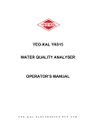
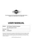
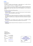
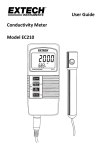
YEO-KAL
YEO-KAL YK611
WATER QUALITY ANALYSER
OPERATOR’S MANUAL
Y E O - K A L
E L E C T R O N I C S
P T Y
L T D
© 2002
YEO-KAL Electronics Pty Ltd,
Unit 18/26 Wattle St, Brookvale,NSW,2100, Australia
Information in this document is the copyright of YEO-KAL Electronics Pty Ltd and is subject to
change without notice. No part of this document may be copied or reproduced by any means
without the express written permission of YEO-KAL Electronics Pty Ltd. All trademarks are the
property of their respective companies.
Revision 2D
1
CONTENTS
1.
INTRODUCTION ........................................................................................ 1
1.1 GENERAL DESCRIPTION ............................................................................... 1
1.2 SPECIFICATIONS .......................................................................................... 1
1.2.1 Reader Unit: ........................................................................................... 1
1.2.2 Sensors ................................................................................................... 2
1.3 DESCRIPTION OF READER UNIT ................................................................... 5
1.3.1 Connector Pins ....................................................................................... 5
1.4 DESCRIPTION OF PROBE .............................................................................. 7
1.4.1 Temperature Sensor ............................................................................... 8
1.4.2 Dissolved Oxygen Sensor ...................................................................... 9
1.4.3 Conductivity Sensor ............................................................................... 9
1.4.4 Turbidity Sensor................................................................................... 10
1.4.5 PH/ORP Sensor ................................................................................... 10
2.
ASSEMBLY ................................................................................................ 11
2.1 CONNECTING THE PROBE ASSEMBLY ........................................................ 11
2.2 CONNECTING AN EXTERNAL POWER SUPPLY ............................................ 11
3.
OPERATION .............................................................................................. 12
3.1 OPERATING INSTRUCTIONS ........................................................................ 12
3.2 ALTITUDE AND SALINITY CORRECTIONS. .................................................. 14
3.3 DISPLAY CONTRAST .................................................................................. 14
3.4 USING THE READER UNIT MEMORY .......................................................... 14
3.4.1 Programming the Reader Unit ............................................................. 15
3.4.2 Clearing Reader Unit Memory. ............................................................ 16
3.5 DOWN LOADING DATA.............................................................................. 17
3.6 DATA PORT OFF/ON ................................................................................ 18
4.
CALIBRATION ......................................................................................... 19
4.1
4.2
4.3
4.4
4.5
4.6
4.7
4.8
5.
TEMPERATURE CALIBRATION .................................................................... 21
HIGH CONDUCTIVITY/SALINITY CALIBRATION .......................................... 22
LOW CONDUCTIVITY CALIBRATION ........................................................... 23
DISSOLVED OXYGEN CALIBRATION ........................................................... 23
PH CALIBRATION ...................................................................................... 24
ORP CALIBRATION ................................................................................... 25
TURBIDITY CALIBRATION .......................................................................... 26
DEPTH CALIBRATION ................................................................................. 26
MAINTENANCE ....................................................................................... 28
5.1 READER UNIT MAINTENANCE ................................................................... 28
5.1.1 Reset..................................................................................................... 28
5.1.2 Battery Replacement ............................................................................ 28
2
5.2 D.O. SENSOR MAINTENANCE .................................................................... 29
5.2.1 Changing the Membrane ...................................................................... 30
5.2.2 Dissolved Oxygen Stirrer Maintenance ............................................... 31
5.3 PH/ORP SENSOR MAINTENANCE .............................................................. 31
5.4 TURBIDITY SENSOR MAINTENANCE .......................................................... 33
5.5 CONDUCTIVITY SENSOR MAINTENANCE ................................................... 33
6.
STORAGE .................................................................................................. 35
7.
APPENDIX 1 - CONVERSIONS USED ................................................ 36
8.
APPENDIX 2 - COMPLIANCE ............................................................. 37
9.
APPENDIX 3 - PART NUMBERS ......................................................... 38
3
Chapter 1
Introduction
1. Introduction
The YK611 comes already assembled. The only construction required is to
connect the probe assembly to the reader unit and, if necessary, connect the
external power supply.
1.1 General Description
The YK611 Water Quality Analyser is a robust multi-parameter field
instrument which can be used for real time water quality measurements or
for remote operation using a built in data logger.
The instrument consists of a multi-sensor probe and a reader unit which can
both store and display the data. The probe and reader unit have been
designed to be compact, light weight and easy to use. Data is transferred to
the reader unit using serial communications giving reliable, interference free
measurements. The reader unit controls the operation of the instrument,
provides easy access to the data, control, memory and calibration functions.
The reader unit contains a real time clock and all stored data includes the
date and time of measurement. Both stored data and calibration information
can be easily down loaded to a computer using the YEO-KAL data transfer
programs.
The YK611 comes with an auxiliary battery lead (optional) for connecting
the instrument to an external power supply during extended periods of
remote logging and a storage container to protect the sensors while the
instrument is in storage.
1.2 Specifications
1.2.1 Reader Unit:
Display:
Two lines 16 character alphanumeric LCD.
Memory:
Remote logging - 2135 samples. Real time (store) 600
samples. All samples include date and time. Memory is
backed up by lithium battery to guard against main
battery failure.
Sample Rate:
1 per 2 minutes to 1 per day in Standard Logging Mode
1 per second in Fast Logging Mode
Display update, 2 seconds
Communications:
Baud rate 4800, 8 data bits, 0 parity, 2 stop bits.
1
Chapter 1
Introduction
Power:
Battery pack containing 8 "C" size cells. Memory
backup voltage supplied by ½ AA lithium cell.
Case:
Impact resistance polycarbonate; waterproof display,
keypad, connectors and case.
Dimensions:
130 mm x 95 mm x 190 mm
Weight:
1.6 kg
1.2.2 Sensors
Temperature
Range:
-2 - 50ºC
Accuracy:
±0.05ºC
Resolution:
0.01ºC
Type:
pt 100 platinum element
Conductivity
High Range:
0 - 80 ms/cm
Accuracy:
±0.05 ms/cm
Resolution:
0.02 ms/cm
Low Range:
0-8000 us/cm
Accuracy:
±5 us/cm
Resolution:
3 us/cm
Type:
Four electrode cell
Salinity
Range:
0 - 60 ppt
Accuracy:
±0.05 ppt
Resolution:
0.02 ppt
Type:
See Appendix 1 - Conversions Used
Dissolved Oxygen
Range:
0 - 200% saturation
0 - 20 mg/l
2
Chapter 1
Introduction
Accuracy:
±0.5%
Resolution:
0.1%
Type:
Active silver and lead electrode sensor with PTFE*
membrane and built-in stirrer
Turbidity
Range:
0 - 600 ntu
Accuracy:
±0.5 ntu (0 - 300 ntu range)
±5 ntu (300 - 600 ntu range)
Resolution:
0.3 ntu
Type:
Nephelometric measurement from a 90 sensor with pulsed
infra-red light source
pH
Range:
0 - 14
Accuracy:
±0.03
Resolution:
0.01
Type:
Combination silver/silver chloride type with sintered
Teflon* junction
ORP
Range:
-700 mV to +1100 mV
Accuracy:
±3 mV
Resolution:
1 mV
Type:
Combination bare metal electrode common reference
junction with pH electrode (see Appendix 1 - Conversions
Used)
Depth (optional)
Range:
0 - 100 m or
0 - 150 m
Accuracy:
±0.5% of full scale
Resolution:
0.1 m
Type:
Dual active silicone strain gauge
3
Chapter 1
Introduction
Cable length:
3 m or 10 m. Other lengths made to order.
Dimensions:
50 mm diameter, 320 mm long
4
Chapter 1
Introduction
1.3 Description of Reader Unit
The reader unit is housed in a tough, durable, high impact polycarbonate
case with a keypad and alpha-numeric display mounted on the front panel.
The side of the case has three connectors. The top connector is used for data
output, the second for connecting an external power supply and the third is
the sensor connector. Each connector is provided with a protective cap
which screws over the connector. The connectors also have a polarising pin
so that incorrect connection cannot be made. Inside the reader unit a CPU
controls the operation of the instrument, memory stores data and 8 C size
alkaline batteries power the instrument.
1.3.1 Connector Pins
The connector pins on the reader unit connectors are numbered in clockwise
order from the polarising pin (see figure 1). The following table lists the
purpose of each pin on the connectors.
Communications
Auxiliary Power
Sensor
Pin 1
Ground
Negative
Ground
Pin 2
RS232 out
Positive
Data
Pin 3
RS232 in
not used
+12V
5
Chapter 1
Introduction
Figure 1: Reader unit for the YK611 and Turo
T611 a) Top view showing key pad and
alphanumeric display b) End view showing
connectors.
6
Chapter 1
Introduction
1.4 Description of Probe
The probe assembly consists of sensor, cable and connectors. The body of
the probe is made of PVC with a PVC sensor guard. The interface cable is
permanently connected to the probe body to eliminate the need for
underwater connectors. In the event of the cable being cut, the probe has a
waterproof seal between the cable connection and the electronics package.
At the other end of the cable is a corrosion and water resistant connector for
attaching the assembly to the reader unit.
The sensors can easily be accessed by sliding the sensor guard up and
Figure 2: a) Complete probe assembly b) Sensor cluster exposed
by lifting sensor cage and rotating probe base C) Expanded view
of sensor cluster with dissolved oxygen sensor detached.
7
Chapter 1
Introduction
rotating the bottom section of the probe. (see fig 2b)
The conductivity and dissolved oxygen sensors can be removed for
servicing. However, the whole unit must be thoroughly dry before these
sensors are removed. A cotton bud can be used to dry the spaces in between
the sensors.
Figure 3: End view of probe
(without bottom section) showing
position of sensors.
1.4.1 Temperature Sensor
The temperature sensor consists of a pt 100 platinum element, housed in a
stainless steel sheath for robustness and corrosion resistance. The
temperature sensor requires little maintenance however the temperature
measurement is used for calculating the dissolved oxygen in mg/l and for
temperature correction of the conductivity sensor and so it is important that
the temperature sensor is properly calibrated.
8
Chapter 1
Introduction
1.4.2 Dissolved Oxygen Sensor
Dissolved Oxygen is measured using an active type membrane covered
sensor. The sensor itself consists of silver and lead electrodes and a 25um
ptfe membrane and is filled with a 1.0M potassium hydroxide. A constant
flow of water passes the sensor which is maintained by a stirrer located on
the bottom section of the probe.
When the silver and lead electrodes are connected through the external
circuit, electrons pass from the lead electrode to the silver electrode. When
oxygen is present at the surface of the silver electrode, it reacts with
electrons to produce hydroxyl ions.
At the lead electrode the loss of electrons produces lead ions. The lead's
electrons combine with hydroxyl to precipitate lead hydroxide on the lead
electrode.
The rate of transference of electrons via the external circuit from the lead to
silver electrode ie that is the current flowing in the external circuit, is the
measure of the rate of cell reaction and thus the rate at which oxygen
reaches the silver electrode. The current flowing in the external circuit is
directly related to the oxygen concentration in the sample being measured
by the electrodes.
The Dissolved Oxygen sensor may periodically require a new membrane
and electrolyte. A unique knurled nut is used to hold the sensor membrane
in position without overstressing the membrane. This gives long term
stability and allows easy replacement. The sensor can be removed from the
probe for servicing. A replacement probe is ready for use after installation
and calibration.
1.4.3 Conductivity Sensor
The conductivity is measured using a 4 electrode bridge. The four electrode
system uses automatic compensation to overcome any build up of
contamination on the electrodes. The electrodes are made from fine
platinum and are coated with platinum black to enhance the long term
stability and sensitivity of the sensor. The coating should last for a long
period of time if it is not mechanically removed, however, the coating can
be replaced using the optional platiniser or by returning the sensor to YEOKAL Electronics Pty Ltd.
9
Chapter 1
Introduction
1.4.4 Turbidity Sensor
The turbidity sensor is located in the hole which runs through the bottom
section of the probe and is lined with a glass tube. Turbidity is measured by
the nephelometric method which uses a light source and a detector which
measures light scattered at 90 degrees to the incident light beam. A pulsed
infra-red light source is used.
1.4.5 PH/ORP Sensor
The pH and oxidation reduction potential (ORP) are measured using
separate pH sensor and bare metal platinum electrode for ORP. They both
share an internal reference electrode in the pH sensor. The sensors only
require maintenance if there is a build up of contamination on the electrodes
and/or the reference becomes blocked or depleted of electrolyte.
10
Chapter 2
Assembly
2. Assembly
The YK611 comes already assembled. The only construction required is to
connect the probe assembly to the reader unit and, if necessary, connecting
the external power supply.
2.1 Connecting the Probe Assembly
To attach the probe assembly, first unscrew the knurled connector cap from
the SENSOR connector of the reader unit. The connector cap is attached to
the reader unit by a chain so that it can be replaced whenever the probe
assembly is disconnected. To connect the probe assembly, align the locating
pin on the reader unit with the slot on the cable connector and push the
cable connector into the reader unit sensor connector then screw home the
retaining ring.
2.2 Connecting an External Power Supply
For extended remote logging, the reader unit batteries can be supplemented
by connecting the unit to an external 12 Volt dc power supply such as a car
battery or solar panel. To connect the external power, first attach the
external battery lead to the reader unit. To do this, unscrew the knurled
connector cap from the AUX BATT connector of the reader unit. align the
locating pin on the reader unit with the slot on the cable connector and push
the cable connector into the reader unit connector then screw home the
retaining ring. The connector cap is attached to the reader unit by a chain so
that it can be replaced whenever the external power is disconnected.
Connect the red terminal clamp to the positive terminal of your power
supply and the black clamp to the negative terminal.
11
Chapter 3
Operation
3. Operation
The YK611 comes already assembled. The only construction required is to
connect the probe assembly to the reader unit and, if necessary, connecting
the external power supply.
If the pH sensor has a cap over it, the cap should be removed (SLIDE THE
CAP OFF, DO NOT UNSCREW) prior to operation. See section 6 for
IMPORTANT INFORMATION.
3.1 Operating Instructions
The following is provided as a quick reference for operation of the
instrument. To gain maximum performance and reliability from the YK611,
make sure that you read and understand the entire user manual before
operating the instrument.
The instrument is switched on or off by pressing the center of the ON/OFF
key.
ON
OFF
When the unit is switched on, the display will briefly show the serial
number of the instrument and the version number of the software loaded in
the reader unit. If the probe is connected, the display will then automatically
begin to show the value of readings from the probe. The parameters
displayed will be temperature and one other parameter. If the optional depth
sensor is fitted, then the display will show the depth and one other
parameter Press the arrow keys to scroll the display through the other
parameters.
From here, the main menu is entered by pressing the ENTER/MENU key.
If the sensor is not connected, the main menu is entered automatically when
the instrument is turned on. To scroll through the main menu options, press
the arrow keys. To select a menu item, press the ENTER key. You can
back out of any point in the menu without changing the current settings by
pressing the ESC key.
12
Chapter 3
Operation
The menu options are as follows:
Option
1.
ALT CORRECT
Enter altitude for correcting
D.O. readings
2.
SET LOGGER
Enter a logging program
3.
LOGGER OFF
Halts Logging to memory
4.
CLR STORE MEMORY Clear data entered using the
STORE key
5.
STORE DAT OUT
Down load store data to
computer
6.
LOGGD DAT OUT
Down load logged data to
computer
7.
CHECK BATTERY
Display Battery Voltage
8.
LCD CONTRAST
Alter display contrast
9.
CALIBRATION
Calibrate the sensors
10.
SET CLOCK
Change current time and date
11.
PANEL LIGHT
Switch display light on or off
12.
PRINT CONSTS
Down load calibration
constants to a computer
13.
DATA PORT OFF/ON
Displayed data is output thru
COMMS Port
14.
PROBE S/N
If available, serial number of
probe is displayed.
Notice that main menu options 1, 2, 9 and 10 require that all data be cleared
from memory. You will be asked for conformation before memory is
cleared.
The reader unit can be turned off without losing any of the instrument
settings. If the logger is activated, the unit will continue to record
measurements even if the reader unit is turned off.
13
Chapter 3
Operation
To check the date and time with the display in real time, press the
ENTER key. The date and time will appear on the LCD for approximately
3 seconds, then it will return to the original display.
3.2 Altitude and Salinity Corrections.
The solubility of oxygen in water is less in brackish or sea water than in
fresh water and also decreases with increasing altitude. For dissolved
oxygen concentration measurements to be accurate, they must be
compensated for the salinity of the water being tested and for the
atmospheric pressure. The YK611 will calculate the correct value of
dissolved oxygen concentration and percent saturation once you have
entered the altitude for the particular sample being tested, salinity
corrections are made automatically.
1.
With the instrument deployed, select 1)
ALT
CORRECTION from the main menu and press ENTER.
2.
Press the arrow keys until the display shows the correct
altitude in meters. Press ENTER. The altitude which you
have entered will remain until it is changed, even if you
turn the instrument off.
3.3 Display Contrast
When the instrument is used in the field, variations in ambient light and
temperature may make the display difficult to read. This can be remedied by
adjusting the display contrast.
To make this adjustment, start with the display showing dissolved oxygen
and temperature readings. Press one of the arrow keys to enter the main
menu and continue to press the arrow keys until the message 8) LCD
CONTRAST appears then press enter. Now press the up or down arrow
keys until the display is easier to read then press ENTER or ESC to return
to the main menu.
3.4 Using the Reader Unit Memory
The reader unit has two separate memories: the store memory and the logger
memory. The logger memory can hold up to 2135 readings and the store
memory can hold up to 600 readings. Once stored, the data can then be
down loaded into a computer via the YEO-KAL software or printed at a
later date.
14
Chapter 3
Operation
The store memory is used to hold spot measurements. To store a reading
while in the field simply press the STORE key. The data will be down
loaded in the order in which it is stored so keep a record of the site at which
each measurement was made so that the data can be easily analysed.
The YK611 can also be programmed to take measurements at regular
intervals and store the results in the logger memory.
The fastest sample rate in Standard Logging Mode is one per two minutes,
the stirrer is activated one minute before the sample is to be taken and will
switch off immediately after the data has been recorded.
In Fast Logging Mode the sample rate is 1 per second.
3.4.1 Programming the Reader Unit
To program the logger for a measurement routine, perform the following
steps:
1.
Enter the main menu, select 2 SET LOGGER and press
ENTER. If the logger memory is empty and the logger
disarmed, the message -SET START TIME- will be
displayed with a date displayed underneath.
If there is data in the logger memory, the message CLEAR
LOGGER will appear on the display. Press ENTER to
clear the memory or ESC to return to the main menu. If
there is a current logging routine, the message DISARM
LOGGER will appear. Press ENTER to reprogram the
logger or ESC to return to the main menu.
If the logger memory is empty and the logger disarmed (see
3. below), the message –FAST LOG (Y) ENT or (N) ESC
appears. If ENTER is pressed the unit will immediately
commence to log at approximately once every second. This
is the Fast Logging Mode. If ESC is pressed the message
SET START TIME will be displayed with a date displayed
underneath. This will set up the Standard Logging Mode.
2.
15
The first step in programming the logger is to set the date
and time at which you wish logging to commence. When
you first start the SET LOGGER routine, a date will be
displayed with the day shown as a flashing number. Use the
Chapter 3
Operation
arrow keys to change the day and then press ENTER. The
month will now begin to flash. Use the arrow keys to set
the appropriate month and press ENTER then, in a similar
fashion, set the desired year and press ENTER. The display
will then show the time at which logging is to commence
and the number corresponding to the hour will be flashing.
The time is displayed in 24 hour time in the format
HH:MM where HH is the hour and MM is the minute. Use
the arrow keys to set the required hour and then press
ENTER, set the required minutes, and press ENTER
again. The message -SET STOP TIME- will now be
displayed. This is the date and time at which logging will
stop and is set in the same manner as the start time.
3.
When the start and stop times have been set, you will be
asked to set the sample rate. The sample rate is changed by
again pressing the arrow keys to scroll through the
available choices. When the desired sample rate is
displayed press ENTER. The message CLEAR LOGGER
MEM? Y)-ENTER, (N)- ESC. If the ENTER key (CLEAR
LOGGER MEM) is pressed existing data will be cleared
and new data will be stored at the beginning of memory. If
ESC is pressed the existing logged data will remain and
new data will be stored contiguously from the last data
point. The message LOGGER ARMED will be briefly
displayed and the instrument then automatically returns to
the main menu.
The instrument is now programmed and can be switched off. The logger
will automatically switch on the stirrer 1 minute before the programmed
measurement time and the message AUTO LOG SAMPLES STIRRING
will be displayed. When the sample has been taken, the instrument will
automatically shut down again until the next sample time has arrived.
To halt the logging process, select 3) LOGGER OFF from the main menu.
You will then see the message CONFIRM (ENT/ESC) press ESC to
continue logging or ENTER to stop the logging routine.
3.4.2 Clearing Reader Unit Memory.
To erase data from the memory, enter the main menu and, using the arrow
keys, scroll to 9 CLEAR MEMORY then press ENTER. Use the arrow
16
Chapter 3
Operation
keys to select the store memory or the logger memory and press ENTER.
You are then asked to confirm that you really want to delete the data in
memory, if so press ENTER or else press ESC.
3.5 Down Loading Data
Data stored in the YK611 can be down loaded to a computer and then
stored, graphed or printed out using most popular applications. The data can
also be sent directly to a printer. When the data is down loaded, it includes a
header, as shown in figure 4 below, indicating whether the data is from the
logger or store memory.
All the parameters recorded are averaged over 10. This enhances the quality
of the data by smoothing out any unwanted transients.
Calibration coefficients
Serial Number
0
Cal
DATE/TIME
Sensor
01/12/02
18:00
Depth
01/12/02
18:00
Temperature
01/12/02
18:00
Sal/Cond ms/cm
01/12/02
18:00
Cond us/cm
01/12/02
18:00 Dissolved Oxygen
01/12/02
18:00
pH
01/12/02
18:00
ORP
01/12/02
18:00
Turbidity
AUTO LOGGED DATA
SERIAL NUMBER:
Offset
****
****
****
****
****
****
****
****
Slope
****
****
****
****
****
****
****
****
1
SAM
TEMP COND COND SAL DO
DO
PH ORP TURB
NUM
DATE
TIME
C ms/cm us/cm ppt %sat mg/l pH
mv
ntu
-----------------------------------------------------------------------1 01/12/02 18:43:00
2.0
0.9
879 0.5
0.0 0.0 7.4 224
3.8
2 01/12/02 18:45:00
2.1
0.9
877 0.5
0.0 0.0 7.4 227
4.0
3 01/12/02 18:47:00
2.2
1.0
879 0.5
0.0 0.0 7.4 228
4.2
4 01/12/02 18:49:00
2.2
1.0
877 0.5
0.0 0.0 7.4 230
4.2
5 01/12/02 18:51:00
2.3
1.0
875 0.5
0.0 0.0 7.4 231
4.2
6 01/12/02 18:53:00
2.4
0.9
872 0.5
0.0 0.0 7.4 232
4.2
7 01/12/02 18:55:00
2.5
1.0
869 0.5
0.0 0.0 7.4 233
4.2
8 01/12/02 18:57:00
2.6
1.0
867 0.5
0.0 0.0 7.4 234
4.0
9 01/12/02 18:59:00
2.7
1.0
868 0.5
0.0 0.0 7.4 235
3.8
10 01/12/02 19:01:00
2.8
1.0
866 0.5
0.0 0.0 7.4 235
3.8
-----------------------------------------------------------------------Figure 4: Sample of data output from the YK611 (date format: dd/mm/yy).
17
Chapter 3
Operation
In order to down load the data stored in memory to a computer, you will
need a copy of the YEO-KAL Data Transfer program or YEO-KALGraph
and the purpose built communications cable. To transfer data, perform the
following operations:
1.
Connect the 3 pin connector of the communications cable
to the COMMS connector of the reader unit, (see figure 1).
Connect the other end of the cable to an RS232 (serial
communications) port on your computer.
2.
Start your data transfer program and prepare it for receiving
data.
3.
Switch on the YK611 and select 5) STORE DAT OUT to
down load data from the store memory or select 6) LOGGD
DAT OUT to down load data from the logger memory or
12) PRINT CONSTS to down load the calibration
constants, then press ENTER. The unit will then display
the message DOWNLOADING DATA and down load data
to your computer. When the operation is finished, the
instrument will automatically return to the main menu.
3.6 Data Port OFF/ON
When Data Port is ON, displayed data is outputted from the serial
communications port. This can be directly linked to a computer where data
can be displayed and/or stored onto a disk. The unit also enables:
a)
storage of data directly into its memory while
outputting data to a P.C. This is accomplished by:
b)
Switching the unit ON, then going to the set
logging routine. Set up the desired stop/start times
and sample rates. Then go to main menu and switch
Data Port ON. Do not switch the unit OFF. The
unit will immediately transmit data to the serial port
and start logging when the start time is reached.
c)
Output displayed data only, this is accomplished
by:
Switching the unit ON, then go to Data Port
ON/OFF on the main menu and press ENTER.
18
Chapter 4
Calibration
4. Calibration
In order to ensure the accuracy of the YK611, the instrument needs to be
calibrated on a regular basis as well as after any maintenance has been
performed on the probe. The frequency at which calibration is required will
depend on the specific application for which the instrument is to be used.
The optimum time between calibrations can be established by regularly
checking the performance of the instrument in standard solutions. If the
YK611 is kept well maintained and calibrated on a regular basis, a single
point calibration is sufficient to keep the instrument performing to
specification. However, two point calibrations whenever a sensor has had
any maintenance.
The calibration procedures require that the probe be immersed in standard
solutions. The probe storage container which is supplied with the YK611 is
ideal for this purpose as it provides a water tight seal on the probe and
minimizes the volume of standard solution required (about 150 ml). Make
sure that you rinse both the probe and container before each calibration and
between each calibration solution. The standard solutions are available from
YEO-KAL Electronics Pty Ltd or most major scientific suppliers.
Both dissolved oxygen and conductivity measurements require a correction
for temperature (this correction is automatically made by the instrument)
hence the temperature sensor must be correctly calibrated before you can
calibrate either the dissolved oxygen or salinity / conductivity sensors.
To enter the calibration menu, choose option 9) CALIBRATION from the
main menu and press ENTER. If there is any data in the reader unit
memory, the message CLEAR ALL MEM? will appear on the display. Press
ENTER to clear memory or ESC to return to the main menu. Once you
have entered the calibration menu, use the arrow keys to scroll through the
menu and select the sensor which you wish to calibrate by pressing
ENTER.
If the user mistakenly places the probe into the incorrect solution ie high
standard instead of a low standard the message will appear on the LCD
display "CALIBRATION ERROR RECAL HIGH & LOW". To remove the
message recalibrate the sensor correctly. Note: This does not ensure that the
unit is calibrated accurately, but does ensure that a major mistake or error
does not occur.
19
Chapter 4
Calibration
During calibration, the display shows a D number (“D = ”). These are the
raw numbers from the analogue to digital converter prior to conversion to
real units (such as °C temperature or mS/cm conductivity or %sat dissolved
oxygen, etc). Calibration coefficients are used to convert the D number to the real
units.
20
Chapter 4
Calibration
4.1 Temperature Calibration
The temperature calibration should vary very little over the lifetime of the
instrument however it is worth checking on the accuracy of your
temperature measurements before calibrating the dissolved oxygen or
salinity sensors.
Temperature calibration is performed at two temperatures. The low
temperature must be between 0 and 20 C and the high temperature must be
between 30 and 50C. To calibrate temperature, proceed as follows:
21
1.
Select TEMPERATURE from the calibration menu. The
message CAL TEMP oC will appear, press ENTER to
calibrate or ESC to main menu. The message 0-20C
(ENT/ESC) will appear. Press ENTER to calibrate the low
temperature range or ESC to proceed directly to the high
range calibration.
2.
If you proceed with the low range calibration, the raw data
D is displayed. Immerse the probe in a stirred water bath
held at a constant temperature between 0 and 20 C and wait
until the probe and water bath reach thermal equilibrium.
Raw temperature data is displayed on the lower left hand
side of the LCD display. When the data is stable press
enter. Press the arrow keys to change the displayed
temperature to the correct value then press ENTER. The
message 30-50C (ENT/ESC) will now appear. Press ESC
to exit the temperature calibration or ENTER to continue
with the high temperature range calibration.
3.
If you proceed with the high range calibration, the message
CAL TEMP oC 25-50 Press ENTER OR ENTER will
appear. Press ENTER, the raw data D is displayed.
Immerse the probe in a stirred water bath held at a constant
temperature between 25 and 50 C and wait for the probe to
reach a constant temperature. Press the arrow keys to
change the displayed temperature to the correct value then
press ENTER. The temperature calibration is now
complete.
Chapter 4
Calibration
4.2 High Conductivity/Salinity Calibration
The conductivity/salinity sensor is calibrated using solutions with a salinity
of 0 ppt (air calibration) and 35 ppt. Conductivity is a parameter derived
from the salinity measurement and so calibrating salinity simultaneously
calibrates the conductivity measurements. To calibrate the sensor, proceed
as follows:
1.
First, ensure that the temperature sensor is reading
accurately and, if necessary, perform the temperature
calibration described above.
2.
Select CONDUCTIVITY from the calibration menu, the
message 0 PPT (ENTER/ESC) will be displayed. Press
ESC to exit without changing the calibration.
3.
If you wish to continue for low calibration, leave the probe
in air, a visual display of the raw data is seen on the bottom
left hand side of the LCD display. When the raw data D is
stable press ENTER, the salinity calibration coefficient
will then be automatically updated.
4.
If you wish to continue for an upper calibration, immerse
the probe in a solution with a salinity of 30-40 ppt, Press
ENTER; a visual display of the raw data D is seen on the
bottom left hand side of the LCD display. When the data is
stable press ENTER, then use the UP/DOWN arrows keys
to set the salinity value of the solution that was used and
then the calibration coefficient will be automatically
updated and the instrument will return to the calibration
menu.
22
Chapter 4
Calibration
4.3 Low Conductivity calibration
1.
Select CAL C25 us/cm from the main menu press ENTER
to continue or ESC and go to main menu.
2.
To proceed with the low conductivity calibration press
ENTER. Leave the probe in air and press ENTER for zero
conductivity calibration.
3.
If you wish to continue for an upper calibration, immerse
the probe in a KCl solution. To prepare the solution,
dissolve 0.7459 grams anhydrous KCl in distilled water and
make up the solution to 1 litre. This has an electrical
conductivity of 1413 umhos/cm. The raw data will be
displayed on lower left hand side of the display. When the
raw data D is stable press ENTER. Then use the
UP/DOWN arrows keys to set the conductivity value of the
solution that was used and then the calibration coefficient
will be automatically updated and the instrument will return
to the calibration menu.
Other conductivities can be selected between 100 to 8000 us/cm. It is
advisable to use the solution of KCl which has the conductivity of
1413us/cm. The calculation for temperature correction is at its optimum
when this value is used. If other standards are used the temperature changes
in the sample will cause small changes in the displayed conductivity.
4.4 Dissolved Oxygen calibration
Dissolved oxygen calibration is performed using solutions with zero % and
100% oxygen saturation. To prepare a sample with zero % saturation,
dissolve 26 grams of sodium sulphite in 500 ml of water and add 0.2 grams
of cobalt chloride. Stir the solution until the crystals are dissolved. Discard
the solution after 30 minutes as it will begin to absorb oxygen. Alternatively
use the optional dummy zero plug. To make a solution with 100%
saturation, aerate a sample of fresh water for about two hours. A fish tank
air pump and air stone is ideal for this purpose. When you have the
calibration standards ready, perform the following steps:
1.
23
Before calibrating dissolved oxygen, ensure that the
temperature sensor is reading accurately and, if necessary,
perform the temperature calibration described above. If the
Chapter 4
Calibration
membrane has been replaced wait 2 hours before doing the
calibration. You should also check that the stirrer is
operating correctly. The paddle should oscillate freely when
the instrument is performing measurements.
2.
Select DISSOLVED OXYGEN from the calibration menu,
the message CAL DO % sat (ENTER/ESC) will be
displayed. Press ESC to exit without changing the
instruments calibration.
3.
If you wish to continue, immerse the probe in the 0%
oxygen solution, a visual display of the raw data for zero
can be seen at the bottom left hand side of the LCD display.
When the data is stable press ENTER, the dissolved
oxygen calibration coefficients will then be automatically
updated and the message 100% SAT (ENTER/ESC) will
be displayed.
4.
Immerse the probe in the aerated solution, a visual display
of the raw data is seen on the bottom left hand side of the
LCD display. When the data is stable press ENTER, the
dissolved oxygen calibration coefficients will then be
automatically updated and the instrument will return to the
calibration menu.
4.5 pH Calibration
The pH sensor is calibrated using buffer solutions with a pH of 3 - 9 and 612. To calibrate the pH sensor, proceed as follows:
1.
Select pH from the calibration menu, the message CAL pH
(ENTER/ESC) will be displayed. Press ESC to exit without
changing the instruments calibration.
2.
If you wish to continue, immerse the probe in a solution of
the desired pH between 3 and 9, Press ENTER a visual
display of the raw data is seen on the bottom left hand side
of the LCD display. When the data is stable press ENTER.
Press the arrow keys to change the displayed pH to the
correct value (whichever was selected between 4 and 9)
then press ENTER, the pH calibration coefficients will
then be automatically updated.
24
Chapter 4
3.
Calibration
Rinse the probe in distilled water to remove all traces of the
low buffer solution. Immerse the probe in a buffer solution
with pH between 6 and 12, press ENTER and a visual
display of the raw data is seen on the bottom left hand side
of the LCD display. When the data is stable press ENTER.
Press the arrow keys to change the displayed pH to the
correct value (whichever was selected between 6 and 12)
then press ENTER, the pH calibration coefficients will
then be automatically updated and the instrument will
return to the calibration menu.
4.6 ORP Calibration
Oxidation reduction potential is factory calibrated using standard solutions
producing ORP of 295.2 mV and 472.2 mV. Other solutions within the
ranges of 50 – 500mV and 250- 500mV can be selected.
To prepare the 295.2 mV solution, measure out enough pH 7 buffer to cover
the ORP sensor and saturate the solution with quinhydrone. This will only
require a small amount of quinhydrone and is best done by adding a pinch
and then stirring for 30 seconds. There should still be solid, undissolved
quinhydrone in the solution. If no solid is seen, add an additional amount
and repeat stirring until solid quinhydrone is seen. To prepare the 472.2 mV
standard, repeat the above except use pH 4 buffer instead of pH 7. Perform
the calibration as follows:
25
1.
Select ORP from the calibration menu, the message CAL
ORP mv (ENTER/ESC) will be displayed. Press ESC to
exit without changing the ORP calibration.
2.
If you wish to continue, immerse the probe in 295.2 mV
solution, a visual display of the raw data is seen on the
bottom left hand side of the LCD display. When the data is
stable press ENTER, using the arrow keys, select 295mV
from the range of 50 – 300mV the ORP calibration
coefficients will then be automatically updated.
3.
Immerse the probe in solution 472.2 mV solution, press
ENTER a visual display of the raw data is seen on the
bottom left side of the LCD display. When the data is stable
press ENTER using the arrows select the 472mV from the
range of 250 – 500mV and press ENTER the ORP
Chapter 4
Calibration
calibration coefficients will then be automatically updated
and the instrument will return to the calibration menu.
4.7 Turbidity Calibration
The turbidity sensor is calibrated using solutions with a turbidity of 0 ntu
(distilled water) and a high value between 10 - 600 ntu's. These solutions
can be prepared by diluting a concentrated formazin solution. Beware,
formazin is a suspected carcinogen. Always wear rubber gloves when
handling formazin solutions. Note: Always clean the glass tube before
calibration. To calibrate the turbidity sensor, proceed as follows:
1.
Select TURBIDITY from the calibration menu, the
message CAL TURB ntu (ENTER/ESC) will be displayed.
Press ESC to exit without changing the turbidity
calibration.
2.
If you wish to continue, immerse the probe in distilled
water press ENTER a visual display of the raw data is seen
on the bottom left hand side of the LCD display. When the
data is stable press ENTER, the turbidity calibration
coefficients will then be automatically updated.
3.
Immerse the probe in solution with turbidity between 100
and 600ntu's, press ENTER a visual display of the raw data
is seen on the bottom left hand side of the LCD display.
When the data is stable press ENTER. Press the arrow
keys to change the displayed value to the correct value
(whichever was selected between 10 and 600) then press
ENTER, the turbidity calibration coefficients will then be
automatically updated and the instrument will return to the
calibration menu.
4.8 Depth calibration
If the optional depth sensor is fitted then it will also require calibration. To
perform the depth calibration you need to lower the probe to a known depth
in the water. This can be done by placing a mark on the probe cable at a
measured distance from the bottom of the probe assembly then, making sure
that the probe cable is vertical, lower the probe until the mark is at the
surface of the water.
26
Chapter 4
27
Calibration
1.
Select DEPTH from the calibration menu, the message
CAL DEPTH M. (ENTER/ESC) will be displayed. Press
ESC to exit without changing the depth calibration.
2.
If you wish to continue, make sure that the probe is above
the surface of the water and press ENTER, the raw data
will be displayed on the bottom left hand side of the LCD
display depth calibration coefficients will then be
automatically updated. Submerge the probe to your pre
measured depth and make sure that the cable is vertical.
Press the ENTER key keys to from 1 to 100 meter points.
Press ENTER the raw data will be displayed on the bottom
left hand side of the LCD display. When stable press
ENTER and use the arrow keys to change the display to
the correct value then press ENTER. The depth calibration
is now complete.
Chapter 5
Maintenance
5. Maintenance
5.1 Reader Unit Maintenance
The reader unit requires little maintenance except to change the batteries as
necessary and the connectors are kept clean and dry. When the voltage from
the battery pack falls below 7.2 volts, the reader unit display the message
BATTERY FLAT then record the date and time at which this occurred. The
instrument will then automatically shut down, although any data stored in
the memory will be retained. When this occurs, the only way to restart the
instrument is to replace the batteries. Ensure that the connector caps are
secured onto any connectors which are not in use.
5.1.1 Reset
The system can be RESET if the reader unit fails to function properly (hang
up) or exhibiting the following:
The reader unit will not switch ON or OFF
LDC display will not display all the characters
Press keys will not operate reliably
The RESET function is initiated by keeping the ESC key depressed while
pressing the ON/OFF key. The message on the LCD display will ask you if
you wish to continue or escape. Press the ENTER key for yes. It will then
ask you if the unit is fitted with a depth sensor. If there is no depth sensor
fitted on the probe press the ESC key, if there is a depth sensor then press
the ENTER key.
The RESET function will not change or clear the calibration constants from
the reader unit’s memory.
5.1.2 Battery Replacement
The procedure for replacing the reader unit batteries is as follows:
1.
Turn off the instrument and place the reader unit face down
on a clean dry table and remove the four stainless steel
retaining screws under the front panel flange.
2.
Turn the unit upright and lift the front panel from the body
of the reader unit and place it face down on the lid. Unplug
28
Chapter 5
Maintenance
the battery lead connector (the one with red and black
wires) on the printed circuit board.
3.
Unscrew the battery carrier retaining screw (the one in the
center of the battery pack) and remove the battery carrier.
4.
Take out the old batteries and replace with eight new "C"
size batteries positioned with the "-" terminals against the
spring connectors of the battery pack.
5.
Place the battery carrier in the reader unit and tighten the
retaining screw. The screw must be firmly secured so that
the batteries do not move during deployment of the
instrument.
6.
Make sure that the rubber gasket on the reader unit lid and
the surfaces in contact with it are clean.
7.
Replace the printed circuit board connector making sure
that it is pushed firmly in place. The connector will only fit
if it is oriented correctly.
8.
Replace the front panel and the four retaining screws,
making sure that you tighten them firmly in a diagonal
pattern.
5.2 D.O. Sensor Maintenance
To maintain the performance and accuracy of the dissolved oxygen sensor,
the membrane should also be replaced if it becomes damaged or
contaminated with organic matter. Clean the membrane with cotton wool
saturated with alcohol
29
Chapter 5
Maintenance
5.2.1 Changing the Membrane
Figure 5: Exploded view of dissolved oxygen
sensor.
To change the membrane, perform the following steps, refer to figure 5.
1.
Remove the dissolved oxygen sensor from the probe. To do
this, lift the sensor guard and rotate the bottom section of
the probe to expose the sensors. Ensure that the probe and
sensors are completely dry. Use a cotton bud to dry the area
between the sensors. Using pliers, lever the dissolved
oxygen sensor out of the probe.
2.
Unscrew the retaining ring and remove the old membrane.
3.
Check the O-ring and discard if it is damaged then flush out
the old electrolyte.
4.
To refill with electrolyte (1.0 M KOH), hold the probe
vertical and place the nozzle of the squeeze bottle beside
the silver electrode. Squeeze the bottle to fill the probe with
electrolyte until it flows over the top of the probe.
5.
Be sure that there are no bubbles inside the sensor.
6.
Take a new membrane and centralise it on top of the
electrode and let it float on the surface.
7.
Place the retaining nut over the membrane and screw down
firmly so that the membrane is well tensioned.
8.
Check that there are no bubbles in the electrolyte. If
bubbles are found, repeat the above procedure.
30
Chapter 5
Maintenance
9.
Apply a smear of O-ring grease to the body of the sensor
and push it back into the probe. Be sure not to damage the
membrane and be sure to push the sensor in until it clicks
into place
10.
Wait at least 2 hours for the sensor to stabilise then
recalibrate the dissolved oxygen readings.
5.2.2 Dissolved Oxygen Stirrer Maintenance
The Stirrer for the dissolved oxygen sensor is a magnetically operated
paddle which oscillates and forces water past the sensor membrane. This
stirrer may occasionally become clogged, particularly if the water you are
testing contains a large amount of magnetic particles. To remove the stirrer
paddle for cleaning, proceed as follows:
1.
Remove the retaining clip that is located on the support
posts. Lift one end from the groove and slide out while
lifting the clip over the paddle.
2.
Be sure not to lose the paddle spacers
3.
Clean the paddle and replace it in the reverse order.
5.2 PH/ORP sensor maintenance
To service the pH sensor it is better to remove the sensor from the probe
housing. This done by drying the probe by shaking of excess water and
drying as best as possible. Then move the probe cage up and swivel the
bottom section to one side. Firmly grasp the pH sensor and pull down.
Slow response or non-reproducible measurements are signs that the
electrodes have become coated or clogged. The glass electrode is
susceptible to coating by many substances. The speed of response, normally
95% of the reading in less than 10 seconds, is dramatically changed if a
coating is present. Usually a rinse with methyl alcohol will remove any
films on the glass and restore the speed of response.
If the methanol rinse does not restore the response, soak the sensor in 0.1
Molar HCl for five minutes. Remove and rinse the sensor with water and
place in 0.1 Molar NaOH for five minutes. Remove and rinse again, then
place the sensor in pH 4.0 buffer for 10 minutes. The response should now
be improved. Do not use abrasive cleaners as this will destroy the sensor.
31
Chapter 5
Maintenance
The pH and ORP electrodes share a common reference (half cell), as the
electrolyte gel becomes exhausted it can become replaced by water and the
pH and ORP sensors become unstable. Unplug the pH sensor as previously
described. An indication if water is present is that the viscosity is low as
compared with gel. The can be seen though the pH sensor housing. If there
is water present either replace with a new pH sensor or return the sensor to
Yeo-Kal for regelling.
After cleaning the sensor, be sure to recalibrate both pH and ORP.
If cleaning the sensor does not restore performance, the sensor will have to
be replaced.
32
Chapter 5
Maintenance
Turbidity Sensor Maintenance
The turbidity sensor requires little maintenance except ensuring that the
glass tube is kept clean. Do not use an abrasive cleaner. Clean the tube with
a soft rag and, if required, detergent. Make sure that you rinse the probe so
that there is no residual detergent film to interfere with the sensor optics.
Make sure that you recalibrate turbidity after cleaning the sensor.
The later 611’s come with a black acetyl screen. This is inserted into the
glass tube to reduce stray infra red from causing errors in clear water. At the
end of the tube are two holes (apertures) that allow the infra red light source
to pass which is then detected at 90 deg to the source. If the probe is berried
in mud these holes may become blocked and obscure the light source. They
can be cleaned by either using a small bottle brush or remove the screen to
clean it.
Remove the screen by unscrewing two retaining screws at the bottom of the
probe, situated on the flange. Pull the tube out and wash it and also clean
the glass tube. Reinsert the screen and do up the two retaining screws.
5.3 Conductivity Sensor Maintenance
To maintain the performance and accuracy of the conductivity / salinity
sensor, the electrodes need to be periodically cleaned and if the platinum
black coating is damaged, the electrodes will need to be re-platinised.
Inspect the sensor on a regular basis. If there is any evidence of a build up
of contamination on the electrodes, then the sensor should be removed and
cleaned using the platiniser unit as described below. If the platinum black
coating is damaged, the electrodes should be cleaned and then re-platinised.
To perform these operations, proceed as follows:
1.
33
To remove the sensor, lift the sensor guard and rotate the
bottom section of the probe to expose the sensors. Ensure
that the probe and sensors are completely dry. Use a cotton
bud to dry the area between the sensors. Pull the
conductivity sensor down out of the probe by hand. Do not
twist the sensor. Ensure that the vacant sensor socket is
kept completely dry.
Chapter 5
Maintenance
2.
To clean the electrodes, plug the sensor into the platiniser
unit. Connect the unit to a 6V power supply (such as a
lantern battery). Fill the platiniser with 0.1M HCl and
switch on the platiniser for 5 minutes. Switch off the
platiniser and rinse with distilled water. Now inspect the
electrodes. If the platinum black coating is intact, replace
the sensor in the probe assembly as described in step 5
below. If the electrodes need to be re-platinised, proceed as
follows.
3.
To strip the old platinum black coating from the electrodes,
plug the sensor into the platiniser unit fill with 5M HCl.
Connect the unit to a 6V power supply and switch the unit
on. The old platinum black will be stripped off the
electrodes. Once completed, switch the platiniser off and
rinse with distilled water.
4.
To replace the electrode coating, plug the sensor into the
platiniser unit and connect to a 6V power supply. To make
the platinising solution, mix 3g of chloroplatinic acid with
0.3g of lead acetate and top up to 100ml with distilled
water. Fill the platiniser with platinising solution and
switch the unit on for 10 minutes. The electrodes will be
plated with a sooty black coating. When complete, rinse the
unit and electrodes with distilled water then fill the unit
with 0.1M HCl and switch on for 2 minutes to remove any
occluded platinum black solution remaining on the
electrodes. Rinse the sensor and platiniser with distilled
water and install the sensor in the probe assembly.
5.
Before installing the conductivity sensor into the probe
assembly, make sure that both the sensor and probe
assembly are dry. Apply a smear of vacuum grease to the
sensor body to ensure that a water tight seal is achieved.
The sensor can only be installed with the black dot on the
electrode housing pointing to the outside of the probe.
Align the sensor and push it into the probe assembly. Be
sure to recalibrate the salinity and low conductivity.
34
Chapter 6
Storage
6. Storage
When storing the instrument, the pH electrode should be kept moist in a
solution of 3M KCl (approximately 22 grams of KCl dissolved in water to
make 100 ml of solution). It is advisable to buffer this solution to bring it to
approximately pH 5 or 6.
This solution may be contained in either the small pH sensor cap (in some
YK611 models) or in the probe storage canister:
If the YK611 pH sensor has a small cap around it, this simply pushes
into place. The solution can be put into this cap for storage of the pH
sensor. If this method is used, a drop of clean water should be put into
the storage container to keep air around the DO sensor damp.
CARE SHOULD BE TAKEN when removing or replacing this cap. DO
NOT UNSCREW THE CAP, (SLIDE THE CAP OFF) The glass
sensor is EXTREMELY DELICATE and should not be bumped or
touched.
Alternatively, the probe storage canister
may be used to hold the storage solution.
The YK611 comes with a storage canister which clamps onto the probe
providing a waterproof seal. Enough storage solution should be put into
the canister so that the pH sensor is kept wet. This allows the instrument
to be stored and transported with the sensors kept immersed in the
storage solution.
35
Appendix 1 - Conversions Used
7. Appendix 1 - Conversions Used
The YK611 measures dissolved oxygen as % saturation and then
automatically converts the reading to milligrams per litre. This conversion is
calculated from the dissolved oxygen solubility tables found in International
Oceanographic Tables vol.2. National Institute of Oceanography 1972.
The conversion between conductivity and salinity is performed using the
Practical Salinity Scale. UNESCO Technical Papers in Marine Science
1983.
The conversion of low conductivity raw data to conductivity referenced to
25 Deg C is performed using constants derived from HANDBOOK OF
CHEMISTRY AND PHYSICS, 1963, Chemical Rubber Publishing
Company, Page 2691, Conductivity of Standard Solutions using KCl,
0.001 M solution.
Redox potential (ORP) conforms to International Standard IEC 746-5,
“Expressions of Performance of Electrochemical Analyzers, Part 5:
Oxidation-Reduction potential”. In accordance with this standard, the
Redox potential is referred to the standard (“normal”) hydrogen electrode
(NHE) and is expressed in mV.
36
Appendix 2 - Compliance
8. Appendix 2 - Compliance
N 10255
37
Appendix 3 - Part Numbers
9. Appendix 3 - Part Numbers
Part Number
Description
YK611-001 Probe assembly
YK611-002 Cable assembly
YK611-003 Dissolved oxygen sensor
YK611-004 pH/ORP sensor
YK611-005 Conductivity sensor
YK611-006 Depth sensor
YK611-007 Dissolved oxygen membrane
YK611-008 Dissolved oxygen O-ring
YK611-009 Dissolved oxygen membrane retaining ring
YK611-010 Dissolved oxygen electrolyte
YK611-011 Platiniser unit
YK611-012 Platinising solution
YK611-013 Sensor storage solution
YK611-014 pH buffer 4.0 1 litre
YK611-015 pH buffer 10.0 1 litre
YK611-016 Salinity standard 35.00 ppt 1 litre
YK611-017 Formazin solution 1 litre
YK611-018 Battery pack
YK611-019 Battery pack c/w batteries
YK611-020 Front panel membrane
YK611-021 Circuit board
YK611-022 Communications cable
YK611-023 Auxiliary 12V supply cable
YK611-024 Auxiliary 12V Bulk head connector
YK611-025 Communications bulk head connector
38
Appendix 3 - Part Numbers
YK611-026 Sensor bulk head connector
YK611-027 YEO-KALGraph graphics software
39