1
MDI Security Systems
10226 San Pedro Ave., Ste. 200
San Antonio, TX 78216
Phone: 210-477-5400
Fax: 210-582-2678
www.mdisecure.com
MDI
TeraMotion
PCI Card
User Guide
MDI TeraMotion PCI Card
(With onboard WatchDog and Alarm I/O.)
Introduction
Thank you for choosing MDI Security System as your digital video
source. You have purchased the latest in MDI’s cutting edge digital video
technology. A feature-rich solution that can be customized to fit most any
application, from full-motion video to extended time-lapse recording. The
MDI TeraMotion PCI card is your anchor-point for Analog to Digital Video
processing. The MDI TeraMotion PCI acts as either a single card solution,
or, with 32 cameras, a dual card solution. As a single stand-alone capture
card, it can achieve a frame rate of 30 frames per second, four cameras, or a
total of 240 frames per second with 2 cards and 8 cameras!
All frame rates are divided among all cameras, when exceeding four
cameras (single card solution), or 8 cameras (dual card solution). For
example, a single card with 16 cameras will yield 4 frames per second for
each camera.
Max. Frame Rates
1 to 4 cameras, single card – 120 fps
1 to 8 cameras, two cards – 240 fps
More than 4 cameras, single card – 64 fps.
More than 8 cameras, two cards – 128 fps.
Page 1
OVERVIEW
Specifications
Dimensions: 6” Long x 37/8” High (15.2cm x 9.8cm).
Inputs: Up to 32 BNC composite video (CVBS).
Outputs: 16 in, 4 out BNC composite video (CVBS).
Power consumption:
5v (PCI bus), 12v 40VA (with External Alarm I/O),
5v (WatchDog).
Recording and Display Frame Rates: (NTSC)
1 Card, 4 to 16 cameras @ 30 to 120 fps.
2 Cards, 4 to 32 cameras @ 60 to 240 fps.
Video Formats: NTSC, PAL, SECAM 352x240, 640x480.
Video Compression Algorithm: Wavelet & Mpeg4.
Maximum Frame Rate: 240 fps with 2 cards. (200 PAL).
Supported Operating Systems: Windows XP.
The upgrade kit consists of the following:
• 1 MDI TeraMotion PCI Video compression card.
• 1 or more Auxiliary Video Input Adapter (AVIA) cable(s).
• 1 Set of Hardware WatchDog Cables.
• MDI application and TeraMotion PCI Drivers installation CD.
• MDI Application User Manual.
• MDI Easy Reference Guide.
• MDI TeraMotion PCI Card Installation Guide.
•
Leave the cards in their protective packaging until you are ready to
install them.
• Use an anti-static wrist strap when handling the cards. If an anti-static
strap is not available, you may be able to discharge static by touching
the chassis. WARNING! If you use this method of discharging static
electricity, the power supply should be powered off and
disconnected from the motherboard, but still be attached by the
power cable to a 3 –prong grounded wall outlet! You must then
remove it from the wall outlet before plugging it back into the
motherboard.
• Handle the cards by the edges only. Do not touch the edge connector
or the exposed circuitry.
Alarm Inputs: End of Line Terminated Dry Contact
Alarm Outputs: Form C Relays. 24Volt, 1Amp maximum.
Page 17
Page 2
TeraMotion Jumpers and Pinouts
5. LOAD THE SOFTWARE
Cameras 1-8
J6
Cameras 9-16
Spot Monitors 1-4
Stand-By Power
J7
J 13
J8
I2C
Alarm
TERAMOTION PCI DRIVER
(Must be installed before RemoteWatch.)
J5
J 11
JP2
LED
WatchDog
Connections
1
P1
PWR
RST
JP1
J4
J3
Relay Outputs
J2
P2
J1
Cameras
Internal
J6 – Video Inputs 1 – 8 (Secondary Card Inputs 17 – 22)
J7 – Video Inputs 9 – 16 (Secondary Card Inputs 23 – 32)
External
P1 – Cameras 1 – 8 & Spot Monitor 1 – 3 (Secondary Card Inputs 17 – 22)
P2 – Cameras 9 – 16 (Secondary Card Inputs 23 – 32)
When Windows starts, it will immediately see a PCI multimedia device and
ask you to install the driver for it. Put the diskette marked “TeraMotion PCI
drivers” into the floppy drive and click OK. If installing from a CD, insert
the Transmitter software CD in the CD drive. Follow the prompts and
Windows will install the drivers. If you are updating the driver, you can
access the Device Manager in Windows XP by right clicking on My
Computer, left click on Properties, and then click the Hardware tab.
Click the Device Manager Button. The TeraMotion PCI card(s) can be
found in the Sound, video and game controllers’ category.
Important! During the driver installation process, you will be prompted
with an alert that the driver has not been digitally signed. You must click
the button labeled ‘Continue Anyway’. The TeraMotion PCI card is fully
compatible with Windows XP. Windows Logo Testing is mostly intended
for products competing on retail shelves. At this time, MDI views
submission to the Windows Logo program as a needless step that would add
additional cost, which would have to be passed on to you.
Spot Monitors
Internal
J13 – Spot Monitors 1 – 3
Relay Outputs
J1 thru J4 – Relays 1 thru 4
Pins 1 and 2 – Normally Closed.
Pins 2 and 3 – Normally Open.
*Factory defaults for all of the outputs is Normally Open.
Page 3
You must complete the driver installation process for the TeraMotion PCI
WDM Audio Capture, though MDI has not implemented this feature.
Windows will detect each TeraMotion Card 4 times for Video and 4
times for Audio. Driver installation must be completed each time.
Page 16
Onboard Parallel Port (Printer Port)
Onboard Legacy Audio
Game Port
IV.
POWER MANAGEMENT SETUP:
1. Power Management: User Define
Note: Turn off all Power Management Features.
2. MODEM Use IRQ: NA
V.
PNP/PCI CONFIGURATION:
1. PNP OS Installed: Yes
2. Resources Controlled by: Manual
3. Reset Configuration Data: Enabled (It is normal for this setting to
always show Disabled when re-entering CMOS setup.)
IRQ 3
assigned to: Legacy ISA(Serial Port 1)
IRQ 4
assigned to: Legacy ISA(Serial Port 2)
IRQ 5
assigned to: PCI/ISA PnP
(Sound Card, MODEM,)
IRQ 7
assigned to: PCI/ISA PnP
(Printer Port)
IRQ 9
assigned to: PCI/ISA PnP
IRQ 10
assigned to: PCI/ISA PnP
IRQ 11
assigned to: PCI/ISA PnP
(The best for TeraMotion
Card)
IRQ 12
assigned to: Legacy ISA
IRQ 14
assigned to: PCI/ISA PnP
(Primary Controller)
IRQ 15
assigned to: PCI/ISA PnP
(Secondary Controller)
Watchdog
5v (Purple Wire) from
power supply
Black
1
Yellow
Standy
Power
White
J17
Yellow
Black
Black
White
JP1
JP2
Red
1
+
Power LED
-
Reset SW
Reset on
Motherboard
Power SW
Power on
Motherboard
+
Violet
-
Red
+
Black
-
LED on case
Violet
Watchdog
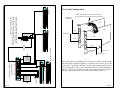
Attach WatchDog header to JP1 and JP2 with wires oriented as shown.
J8 – Standby power for Watchdog. Connect center pin (2) to 5VSB
(Purple wire) from ATX power supply using 26 AWG wire. If you
are using an AT power supply, or cannot attach a wire, a jumper can
be placed over pins 1 and 2.
JP1 – Watchdog Status LED. This connects to the power LED on the
system case. Attach the connector so that the yellow wire goes to
the + Power LED connector from the case, and the Black wire goes
to the – Power LED connector from the case.
JP2 – Reset and Power connectors on the motherboard.
POWER: Attach the female connector so that the red wire goes to the +
(positive), and the black wire goes to the – (negative) power
connector on the motherboard.
Attach the male connector so that the red wire goes to the +
(positive), and the black wire goes to the – (negative) power
connector from the case.
Page 15
RESET: Attach the female connector so that the purple wire goes to the
reset + (positive), and the white wire goes to the reset – (negative)
connector on the motherboard. Attach the male connector so the
purple wire goes to the reset + (positive) connector and the white
wire goes to the reset – (negative) connector from the case.
Page 4
Alarm I/O
The Alarm I/O interface is not required for the TeraMotion card to
operate. Skip this section if you are not using Alarm I/O.
Red stripe align
with pin 1
J8
Jll
I/O Adapter
J5
Red stripe align
with pin 1
To 12V 40VA
Transformer
J4
J5
J6
Teramotion Card
To External 8Digial I/O Relay
Module
J2
External 4-I/O
Relay Terminal
1. Attach the 3-wire cable to J11 with the red wire facing the back of
the computer. Attach the other end to J2 on the I/O Adapter with
the red wire facing the top.
2. Attach the ribbon cable to J5 with the red stripe facing the back of
the computer. Attach the other end to J5 on the I/O Adapter with
the red stripe facing the back of the computer.
3. Place the I/O Adapter in an open slot on the computer and secure it
with a screw.
4. Connect the Relay Terminal to the 15-pin connector of the I/O
Adapter and secure the two screws.
Page 5
5. POWER UP THE SYSTEM AND CHECK CMOS SETTINGS
Before replacing the cover on the computer, turn the power ON and verify
that it goes through the boot up process correctly. While the system is
starting, enter the CMOS setup by pressing the delete key. Most systems
will show a prompt at the bottom of the screen stating ‘PRESS DEL TO
ENTER SETUP’. Some systems will not show the prompt or use F1 to
enter setup. See the motherboard or PC manufacturer documentation for
details, since CMOS settings vary greatly. The following settings will
reside in different areas of the CMOS setup utility and some may not be
available at all.
RECOMMENDED BIOS CONFIGURATION FOR MDI SYSTEMS
Note: In order to leave enough resources for each TeraMotion PCI card
installed in the system, you may have to disable the printer port, game port,
unused onboard sound, and or onboard USB.
I.
STANDARD CMOS SETUP:
1. HARD DISKS: - MODE: Auto
2. Video: EGA/VGA
3. Halt On: No Errors
II.
BIOS FEATURES SETUP:
1. Virus Warning: Disabled
2. CPU Internal Cache: Enabled
3. External Cache: Enabled
4. Quick Power On Self Test: Enabled
5. Assign IRQ For VGA: Disabled (Reserves IRQ for other devices)
6. PCI/VGA Palette Snoop: Disabled
III.
CHIPSET FEATURES SETUP:
1. Auto Configuration: Enabled
2. SDRAM CAS Latency: Depends on the memory. Lower numbers
mean higher performance but can cause instability. Change at your own
risk.
3. On Chip USB: Disabled, if not used.
4. PCI Delay Transaction: Enabled (Enables PCI 2.1 compliance.
Improves Switching Cameras and getting Frames)
IV.
INTEGRATED PERIPHERALS:
Here, you can disable any of the following devices if they are not being
used:
Onboard Serial Port 1 / 2
Page 14
Connecting Output Devices
Output devices can be bells, sirens, lights, speakers or any other device that
can be turned on when an input is activated. The following illustration uses
a light as an output device, but you can substitute any powered security
device.
To connect a powered output device such as a light to Relay 1, connect one
lead of the device to the ground of the power supply, and then connect the
other lead to Relay 1. Relay 1-C connects to the power supply output.
Light
GND
Voltage Out
Before you begin, turn off the computer and unplug any cables from the
back if necessary (be sure and make a note of where the cables attach so that
they can be properly replaced). Take the cover off the computer. Most
computers have four or more screws that hold the cover to the chassis. If
you have a problem, consult the manual that came with the computer, or call
the vendor that supplied the computer. Once the cover is off, attach your
anti-static wrist strap.
2. INSTALL THE CARDS
This procedure is the same for all of the relays.
Power Supply
1. OPEN THE COMPUTER
Connector Card
Relay1
Relay1_C
Connecting an Externally Powered Device to Relay Output
Follow this same procedure to connect powered output devices to the
remaining relays on the 4 I/O Module Connector Board.
If you use an external power supply to power an external device and the
MDI relay output to control it, observe the following precautions:
Select an empty 32-bit PCI expansion slot and remove the slot cover from
the back of the computer. You must use the first PCI slot. It is usually
labeled PCI 1. If a card is already using it, remove the existing card and
place it in an empty slot, if possible. Remove the TeraMotion card from the
anti-static package.
Remember to handle the card by its edges. The TeraMotion PCI Card is
a Plug & Play device so Windows configures the IRQ and I/O ports.
Carefully lower the TeraMotion card into the PCI slot (they are usually
beige or white colored, though not always. Check the PC or motherboard
documentation to identify the slots,) until it touches the connector, then
press down gently until it seats in the slot. Never force the card into the
slot, if it doesn’t want to seat, then it’s not correctly aligned with the slot.
Do not rock the card back and forth to force it to seat. Doing so can damage
the gold pins on the card, or the PCI slot. Secure the card’s bracket to the
chassis using the screw you removed.
1. The relay outputs are floating relative to all other relays and to the
MDI equipment and can be used accordingly.
2. Connect two wires to the relay output. One wire should connect to
the power supply, and the other wire should connect to the external
device to be powered. Do not use the ground on the MDI
equipment as the external power supply’s ground. Do not connect
either of the wires (connected to the relay output) to the ground on
the MDI equipment.
3. If you are absolutely sure the power supply and the external device
are floating, they can be connected to the MDI equipment ground.
Page 13
Page 6
The 4 I/O Module Connector Card
3. CONNECT THE CABLES
The TeraMotion PCI includes external cables for the 25 and 15 pin
connectors. The cables come in two sizes. It is not always necessary to use
both, that depends on how many cameras the system will have.
The 25 – pin connector is for the Spot Monitor outputs and cameras one
through eight. The 15 – pin connector is for cameras nine through sixteen.
Output devices are connected to the Relay terminals on the I/O Relay
Module Connector Card, and input devices are connected to the Zone
terminals. The I/O Relay Module can accept powered output devices, or it
can supply +8VDC 0.05A power. The Input terminals have 5.6k-ohm
resistors installed. Maximum cable length for input devices is 1,000 feet.
For software activation and control, Input 1 will correspond to Output 1,
Input 2 to Output 2 and so on.
Connecting Input Devices
Input devices are connected to the Zone terminals on the I/O Relay Module
Connector Card. The Zone terminals have 5.6k-ohm resistors installed to
permit both open-switch and closed-switch operation. Refer to the
illustration of the I/O Relay Module Connector Card to locate the Zone
terminal.
Spot 1
Spot 2
Spot 3
Camera 1
Camera 2
One end of the input-device cable is inserted into the screw terminal labeled
Zone-1 and the other into the terminal labeled GND, keeping the 5.6 k-ohm
resistor in place for Normally Open operation.
Attach connectors firmly in place
and tighten screws by hand.
Camera 3
One end of the 5.6k-ohm resistor has been removed from terminal Zone 2
and connected to one of the input-device cables. The other cable connects
to GND on the module. Maximum cable length is 1,000 feet.
Camera 4
Camera 5
Camera 6
P1
DB-25
Male
Camera 7
Camera 8
Camera 9
GND
Normally Closed Device
ZONE-2
Camera 10
GND
Camera 11
Camera 12
Camera 13
Camera 14
Camera 15
Camera 16
Page 7
P2
DB-15
Male
5.6k Resistor
Normally Open Device
ZONE-1
This illustrates how both Normally Open and Normally Closed input
devices are attached to the screw terminals of the external 4-I/O Connector
Card. Repeat the applicable procedure for each of the remaining inputs. If
you don’t know whether your device is normally open or closed, it won’t
hurt to wire it one way, then the other. If the input trips constantly, you may
have it wired incorrectly. Set it the other way.
Page 12
Control In
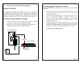
Two Card Configuration
W HEN YOU USE THE POWER /DATA DISTRIBUTORS,
YOU DO NOT NEED TO PLUG THE 12 VAC POWER
3 Spot Monitors,
Cameras 1-8
Card 1
J13
Card 2
Control In
25 pin
J13
Cameras 9-16
25 pin
15 pin
Power /Data
Control cable
SUPPLY TO THE INTERNAL I/O ADAPTER IN THE BACK
OF THE COMPUTER. THE POWER SUPPLIES PLUGGED
INTO THE HUB WILL BE SUFFICIENT.
15 pin
8-DIGITAL I/O MODULES
SUPPLY FOR
1ST 4
12 VAC POWER
THE
POWER OUTS
Control In
Control In
8 Control Cable OUTs
Cameras 17-22
Cameras 23-32
When installing two TeraMotion PCI cards for 32 camera support, attach
the ribbon cable supplied by MDI to J13 from the first card to J13 on the
second card. The 25 pin connector on card #1 will output cameras 1 thru 8
and 3 spot monitors. The 15 pin connector on card #1 will output cameras 9
thru 16. The 25 pin connector on card #2 will output cameras 17 thru 22,
and the 15 pin connector on card #2 will output cameras 23 thru 32.
TO ADDITIONAL
8 DIGITAL I/OS
12 VAC
2ND 4
POWER
THE
SUPPLY FOR
POWER OUTS
POWER/DATA DISTRIBUTOR
Page 11
Ribbon Cable attached to J13 from Board 1 to Board 2.
The colored stripe faces toward the bracket edge of the card.
Page 8
4. ATTACH ALARM I/O DEVICES (Optional)
Attaching multiple 8-Digital I/O Modules
A Power/Data Distributor is required when using more than one 8-Digital
I/O Module.
8-Digital I/O Module
Up to eight external 8-Digital I/O Modules can be used to expand the
I/O capabilities to 68 inputs and outputs. (If you are not using the 4I/O Relay Terminal, the maximum is 64.) When using more than one
8-Digital I/O module, an MDI Power/Data Distributor is required.
Attaching a Single 8-Digital I/O Module
1. Connect the Control Cable to the internal I/O Adapter. Attach the
other end to ‘Control In’ on the 8-Digital I/O Module.
2. Attach the 12VAC 40VA Power supply to the Internal I/O
Adapter. Attach the other end to the wall outlet.
1. Attach a Control Cable to the Internal I/O Relay Adapter. Attach
the other end to the Control In port on the ‘A’ side of the
Power/Data Distributor.
2. Attach another Control Cable to the first Control Out on the ‘A’
side of the Power/Data Distributor. Attach the other end to the
Control In on the first 8-Digital I/O Module. Repeat for the
remaining modules, making sure to set the DIP switches as shown
on the module’s cover.
3. Attach the 12VAC 40VA power supply to the ‘A’ side of the
Power/Data Distributor. If more than four 8-Digital I/O Modules
are being used, attach another power supply to the ‘B’ side of the
Distributor. Attach the power supply plug(s) to the wall outlet.
See diagram on the following page.
Internal I/O Relay Adapter
Power /Data
Control cable to Control IN
8-DIGITAL I/O MODULE
Power supply
Control Cable IN
12VAC
40VA
Control Cable OUT
POWER
SUPPLY
Page 9
Page 10