1
f,
FIATALLIS
EL INJECTION
PUMP
ROOSA MASTER DM Series
service manua
and
parts catalog
Form 73112988 English
2/89
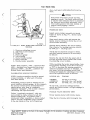
AVOID ACCIDENTS
Most accidents, whether they occur in industry, on the farm, at home or on
the highway, are caused by the failure of some individual to follow simple and
fundamental safety rules or precautions For this reason MOST ACCIDENTS CAN BE
PREVENTED by recognizing the real cause and doing something about it before the
accident occurs.
Regardless of the care used in the design and construction of any type of
equipment there are conditions that cannot be completely safeguarded against without
interfering with reasonable accessibility and efficient operation.
A careful operator is the best insurance against an accident.
The complete observance of one simple rule would prevent many
thousand serious injuries each year.
That rule is
Never attempt to clean, oil or adjust a machine while it is in motion.
WARNING
On machines having hydraulically, mechanically, and/or cable controlled equip- .
ment (such as shovels, loaders, dozers, scrapers, etc) be certain the equipment is
lowered to the ground before servicing, adjusting and/or repairing. If it is necessary to
have the hydraulically, mechanically, and/or cable tontrolled equipment partially or Ailly
raised to gain access to certain items; be sure the equipment is suitably supported by
means other than the hydraulic lift cylinders, cable and/or mechanical devices used for
controlling the equipment.
CALIFORNIA
Proposition 65 Warning
Diesel engine exhaust and some of its constituents are known
to the State of California to cause cancer, birth defects, and
other reproductive harm.
COPYRIGHT BY FIATALLIS
All rights reserved. Reproduction of text and illustrations
in whole or in part, is strictly prohibited.
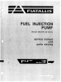
FUEL INJECTION
PUMP
(ROOSA MASTER DM Series)
service manual
and
parts catalog
Form 73112988 English
A
WARNING
STUDY THE OPERATION AND MAINTENANCE
INSTRUCTION MANUAL THROUGH BEFORE STARTING
OPERATING, MAINTAINING, FUELING OR SERVICING
THIS MACHINE.
.
The Operation and Maintenance Instruction Manual provides the
instructions and procedures for starting, operating, maintaining, fueling,
shutdown and servicing that are necessary for properly conducting the
procedures for overhaul of the related components outlined in this
Service Manual.
This symbol is your safety alert sign. It MEANS ATTENTION! BECOME
ALERT! YOUR SAFETY IS INVOLVED.
Read and heed all safety instructions carrying the signal words
WARNING and DANGER.
Machine mounted safety signs have been color coded yellow with
black borders and lettering for warning and red with white borders
and lettering for danger points.
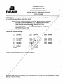
SUPPLEMENT NO. 5
FUEL INJECTION PUMP
(ROOSA-MASTER DM SERIES)
F1AT-ALLIS
SERVICE MANUAL AND PARTS CATALOG
FORM 73112988
( 1-81 )
ATTENTION: Insert this sheet in the front of publication as record of receipt. Replace or add pages
in the publication according to instructions below.
Additional copies of this supplement are available. Please direct your request to:
Fiat-Allis Construction Machinery, Inc., Publications Services Dept.,
3000 South 6th Street, Springfield, Illinois 62710 U.S.A.
or
Fiat-Allis M.M.T. S.p.A. - MAGAZZINO STAMPATI - Vide Torino,
STUPINIGI (Torino) - Italy
Replace the following like pages:
1-7 (No change)
1-8 (Revised)
9-7 (Revised)
9-8 (No change)
12-13 (No change)
12-14 (Revised)
6-3 (Revised)
6-4 (Revised)
11 1 (Revise
11-2 (No
12-25 (Revised)
12-26 (No change)
6-5 (Revised)
6-6 (Revised)
12-3 (R Cr co 0o
12-4 / - 41/4
12-31 (Revised)
12-32 (Revised)
9-1 (Revised)
9-2 (No change)
9-5 (Revised)
9-6 (Revised)
-
■
12
.\.*
co 4,
\4/
ti v\§)
a)
.range )
12-35 (No change)
12-36 (Revised)
,evised)
No change)
REASON: Add spring colors o text; delete (not-used) speed light load
advance informa on; add timing information, page 9-1; include
additional cali • ation data, pages 9-b, 9-6, 9-7; add Fiat-Allis
tool part nu • ers, page 11-1.
Any • roduct change described In this publication is part of the continuing effort of Fiat-Allis to make its product responsive to customer
n • d and is not to be construed as a field campaign. A product change may be incorporated with or without prior notice and without
igation to Fiat-Allis or Its affiliates.
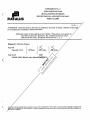
SUPPLEMENT NO. 4
FUEL INJECTION PUMP
(ROOSA-MASTER DM SERIES)
FIAT-ALLIS
SERVICE MANUAL AND PARTS CATALOG
FORM 73112988
( 11-79
ATTENTION: Insert this sheet in the front of publication as record of receipt. Replace or add pages
in the publication according to instructions below.
Additional copies of this supplement are available. Please direct your request to:
Fiat-Allis Construction Machinery, Inc., Publications Services Dept.,
3000 South 6th Street, Springfield, Illinois 62710 U.S.A.
or
Fiat-Allis M.M.T. S.p.A. - MAGAZZINO STAMPATI - Viale Torino,
STUPINIGI (Torino) - Italy
Write in the following changes:
Page 5-16 (after STEP 18)
/I/07-E' ,60 svre fh e
90 varier ,5:70r/r
C
orreci- - - comietvie,
c.etta. I oj
clie..4 4 4,,
Page 5-17 (add at bottom of first column -- in STEP 21) 4,04404,"
Be St rG fLi c advance -5p45k
-orPec-7e -- coo27/0.
the
co r)
zeia1-17
-i-h c ,s pc,
2 d/G4 ?Led
/ 7c2 r./3 Cedir/,' •
Go/or of the Sir'/i79 4a/A C.- 610
•
.csiC
v\SQ ..:ontrol
Page 12-3
27
74061781
1
SPRII•T'
Page 12-7
27
74061836
1
SPRIN , go iernor control 6 ,-seen -diu
Page 12-8
97
74059667
1
Page 12-13
74061836
27
1
SPRING, governor control (9/u e -
Page 12-14
74059662
97
1
SPRING, outer advance itiack -
Page 12-19
27
7406
1
SPRING, governor control 66fire- e Ate)
Page 12-20
97
4059662
1
SPRING, outer advance (ig / a- c4 - peer)
74061836
1
SPRING, governor control (dlue
(Continued)
Page 12 5
CS/
-1Sn owr?.)
RING, outer advance (' e
II ow)
e)
re
-
e
ghee)
Any product change described in this publication is part of the continuing effort of Fiat-Allis to make its product responsive to customer
n d and is not to be construed as a field campaign. A product change may be incorporated with or without prior notice and without
ligation to Fiat-Allis or its affiliates.
SUPPLEMENT NO. 3
FUEL INJECTION PUMP
FIAT-ALLIS
(ROOSA-MASTER DM SERIES)
SERVICE MANUAL AND PARTS CATALOG
FORM 73112988
( 6-79
ATTENTION: Insert this sheet in the front of publication as record of receipt. Replace or add pages
in the publication according to instructions below.
Additional copies of this supplement are available. Please direct your request to:
Fiat-Allis Construction Machinery, Inc., Publications Services Dept.,
3000 South 6th Street, Springfield, Illinois 62710 U.S.A.
Or
Fiat-Allis M.M.T. S.p.A. - MAGAZZINO STAMPATI - Viale Torino,
STUPINIGI (Torino) - Italy
Replace the following like pages:
12-7 (Revised)
12-8 (No cha' •
12-33 (Revised)
12-34 (Added)
9-1
9-2
(Revised)
(No change)
9-3
9-4
(No change)
(Revised)
12-35 (Added)
12-36 (Added)
9-5
9-6
(Revised)
(Revised)
12-37 (Added)
12-38 (Added)
-7 (Added)
9BLANK
v
ti
Reason: Add Service Manual data for new
ries engines.
Any product change described in this publication is part of the continuing effort of Fiat-Allis to make its product responsive to customer
d and is not to be construed as a field campaign. A product change may be incorporated with or without prior notice and without
ligation to Fiat-Allis or its affiliates.
SUPPLEMENT NO. 2
FUEL INJECTION PUMP
(ROOSA-MASTER DM SERIES)
SERVICE MANUAL AND PARTS CATALOG
FORM 73112988
FIATALLIS
( 3-79 )
ATTENTION: Insert this sheet in the front of publication as record of receipt. Replace or add pages
in the publication according to instructions below.
Additional copies of this supplement are available. Please direct your request to:
Fiat-Allis Construction Machinery, Inc., Publications Services Dept.,
3000 South 6th Street, Springfield, Illinois 62710 U. S. A.
Write in the following changes:
Page 9-6
Timing B.T.D.C.
14
16°Static
0
14°
Static
Page 12-13
3500
MK IT
USAGE: 645-B Wheel Loader (Model4c.
,A
e
Cr c) c)
4S 0 i•c?
■
.cs)
O
v\SQ
ti
Any •roduct change described in this publication is part of the continuing effort of Fiat-Allis to make its product responsive to customer need
a is not to be construed as a field campaign. A product change may be incornorated with or without prior notice and without obligation to
iat-Allis or its affiliates.
SUPPLEMENT NO. 1
FIAT-ALLIS
FUEL INJECTION PUMP
(ROOSA-MASTER DM SERIES)
SERVICE MANUAL AND PARTS CATALOG
FORM 73112988
(
1-79 )
ATTENTION: Insert this sheet in the front of publication as record of receipt. Replace or add pages
in the publication according to instructions below.
Additional copies of this supplement are available. Please direct your request to:
Fiat-Allis Construction Machinery, Inc., Publications Services Dept.,
3000 South 6th Street, Springfield, Illinois 62710 U. S. A.
Replace the following pa g es:
V (Revised)
VI (No change)
12-3 (Revised)
12-4 (Revised)
12-19 (Added)
12-20 (Added)
8-1 (Revised)
8-2 (Revised)
12-5 (Rev )
12-6 (Rr
Zsi
12-21 (Added)
12-22 (Added)
8-3 (Revised)
8-4 (Revised)
12-7cd*b.
12-23 (Added)
12-24 (Added)
8-5 (Added)
Blank
12-25 (Added)
12-26 (Added)
9-1 (Revised)
9-2 (Revised)
Lsed)
C
.evised)
c• 4c,
4, c.
v1 (Added)
-12 (Added)
9-3 (Revised)
9-4 (Revised)
12-13 (Added)
12-14 (Added)
12-29 (Added)
12-30 (Added)
9-5 (Added)
9-6 (Added)
12-15 (Added)
12-16 (Added)
12-31 (Added)
12-32 (Added)
12-17 (Added)
12-18 (Added)
12-33 (Added)
Blank
12A‘ oi)
c.3
12-27 (Added)
12-28 (Added)
Reason: To pro ide complete fuel injection pump service, calibration and
parts Information, for the "DM" series pump as applicable to the
262 B, 263-B Scrapers, 545-B, 605-B, 645-B and 745-C Wheel
1 ders and the 100-C, 150-C and 200-C Graders.
Any roduct change described in this publication is part of the continuing effort of Fiat-Allis to make its product responsive to customer need
an is not to be construed as a field campaign. A product change may be incornorated with or without prior notice and without obligation to
at-Allis or its affiliates.
SAFETY RULES
GENERAL
Study the Operation and Maintenance Instruction Manual before starting, operating, maintaining, fueling, or servicing
machine.
Read and heed all machine-mounted safety signs before
starting, operating, maintaining, fueling or servicing machine.
Machine-mounted safety signs have been color coded yellow
with black border and lettering for WARNING and red with
white border and lettering for DANGER points.
Never attempt to operate the machine or its tools from any
position other than seated in the operator's seat. Keep head,
body, limbs, hands and feet inside operator's compartment at
all times to reduce exposure to hazards outside the operator's
compartment.
Do not wear rings, wrist watches, jewelry, loose or hanging
apparel, such as ties, torn clothing, scarves, unbuttoned or
unzipped jackets that can catch on moving parts. Wear proper
safety equipment as authorized for the job. Examples: hard
hats, safety shoes, heavy gloves, ear protectors, safety
glasses or goggles, reflector vests, or respirators. Consult
your employer for specific safety equipment requirements.
Do not carry loose objects in pockets that might fall unnoticed
into open compartments. Do not use machine to carry loose
objects by means other than attachments for carrying such
objects.
DO NOTCARRY RIDERSunless the machine is equipped for
carrying people to reduce personal exposure to being thrown
off.
Do not allow unauthorized personnel to operate service or
maintain this machine.
Do not operate machinery in a condition of extreme fatigue
or illness. Be especially careful towards the end of the shift.
Always check work area for dangerous features. The following are examples of dangerous work areas: slopes, over
hangs, timber, demolitions, fire, high walls, drop off, back fills,
rough terrain, ditches, ridges, excavations, heavy traffic,
crowded parking, crowded maintenance and closed areas.
Use extreme care when in areas such as these.
Roll Over Protective Structures are required on wheel loaders, dozer tractors, track type loaders, graders and scrapers
by local or national requirements. DO NOT operate this
machine without a Roll Over Protective Structure.
An operator must know the machine's capabilities. When
working on slopes or near drop offs be alert to avoid loose or
soft conditions that could cause sudden tipping or loss of
control.
Do not jump on or off machine. Keep two hands and one foot,
or two feet and one hand, in contact with steps grab rails and
handles at all times.
Do not use controls or hoses as hand holds when climbing on
or off machine. Hoses and controls are movable and do not
provide a solid support. Controls also may be inadvertently
moved causing accidental machine or equipment movement.
Keep operator's compartment, stepping points, grab-rails
and handles clear of foreign objects, oil, grease, mud or snow
accumulation to minimize the danger of slipping or stumbling.
Clean mud or grease from shoes before attempting to mount
or operate the machine.
Be careful of slippery conditions on stepping points, hand
rails, and on the ground. Wear safety boots or shoes that have
a high slip resistant sole material.
For your personal protection. Do not attempt to climb on or off
machine while machine is in motion.
Never leave the machine unattended with the engine running.
Always lock up machine when leaving it unattended. Return
keys to authorized security. Heed all shut down procedures of
the Operation and Maintenance Instruction Manual. Always
set the parking brake when leaving the machine for any
reason.
Do not operate a machine without a falling object protective
structure (FOPS).
Do not operate this machine without a rear canopy screen
when machine is equipped with rear mounted towing winch.
Seat belts are required to be provided with roll over protective
structures or roll protection cabs by local or national regulations. Keep the safety belt fastened around you during operation.
Where noise exposure exceeds 90 dBA for 8 hours, wear
authorized ear protective equipment per local or national
requirements that apply.
Keep clutches and brakes on machine and attachments such
as power control units, winches and master clutches adjusted
according to Operation and Maintenance Instruction Manuals
of the manufacturers at all times. DO NOT adjust machine
with engine running except as specified.
Do not operate a machine with brakes out of adjustment. See
the Operation and Maintenance Instruction Manual.
Move carefully when under, in or near machine or implements. Wear required protective equipment, such as hard
hat, safety glasses, safety shoes, ear protectors.
To move a disabled machine, use a trailer or low boy truck if
available. If towing is necessary, provide warning signals as
required by local rules and regulations and follow Operation
and Maintenance Instruction Manual recommendations. Load
and unload on a level area that gives full support to the trailer
wheels. Use ramps of adequate strength, low angle and
proper height. Keep trailer bed clean of clay, oil and all materials that become slippery. Tie machine down securely to
truck or trailer bed and block tracks (or wheels) as required by
the carrier.
SAFETY RULES
To prevent entrapment in cabs or mounted enclosures,
observe and know the mechanics of alternate exit routes.
Use recommended bucket for machine and material load
ability and heaping characteristics of material, terrain, and
other pertinent job conditions.
On machines equipped with suction radiator fans, be sure to
periodically check all engine exhaust parts for leaks as
exhaust gases are dangerous to the operator. Keep a vent
open to outside air at all times when operating within a closed
cab.
Avoid abrupt starts and stops when transporting a loaded
bucket.
Inspect your seat belt webbing and hardware at least twice a
year for signs of fraying, wear or other weakness that could
lead to failure.
STARTING FLUID IS FLAMMABLE. Follow the recommendations as outlined in the Operation and Maintenance Instruction Manual and as marked on the containers. Store containers in cool, well-ventilated place secure from unauthorized
personnel. DO NOT PUNCTURE OR BURN CONTAINERS.
Use only designated towing or pulling attachment points. Use
care in making attachment. Be sure pins and locks as provided are secure before pulling. Stay clear of draw bars,
cables or chains under load.
Follow the recommendations of the manufacturer for storage
and disposal.
When pulling or towing through a cable or chain, do not start
suddenly at full throttle. Take up slack carefully. Guard
against kinking chains or cables. Inspect carefully for flaws
before using. Do not pull through a kinked chain or cable due
to the high stresses and possibility of failure of the kinked
area. Always wear heavy gloves when handling chain or
cable.
Wire rope develops steel slivers. Use authorized protective
equipment such as heavy gloves, safety glasses when handling.
OPERATION
Before starting machine, check, adjust and lock the operator's
seat for maximum comfort and control of the machine.
Be sure cables are anchored and the anchor point is strong
enough to handle the expected load. Keep exposed personnel clear of anchor point and cable or chain. DO NOT PULL
OR TOW UNLESS OPERATOR'S COMPARTMENT OF
MACHINES INVOLVED ARE PROPERLY GUARDED
AGAINST POTENTIAL CABLE OR CHAIN BACKLASH.
DO NOT START OR OPERATE AN UNSAFE MACHINE
Before working the machine, be sure that any unsafe condition has been satisfactorily remedied. Check brakes, steering
and attachment controls before moving. Advise the proper
maintenance authority of any malfunctioning part or system.
Be sure all protective guards or panels are in place, and all
safety devices provided are in place and in good operating
condition.
During operation always carry ripper in full raised position
when not in use and lowered to ground when parked.
When counterweights have been provided, do not work
machine if they have been removed unless their equivalent
weight has been replaced. See the Operation and Maintenance Instruction Manual.
Check instruments at start-up and frequently during operation.
Do not run the engine of this machine in closed areas without
proper ventilation to remove deadly exhaust gases.
When operating a machine know what clearances will be
encountered, overhead doors, wires, pipes, aisles, roadways; also the weight limitations of ground, floor, and ramps.
Be sure exposed personnel in the area of operation are clear
of the machine before moving the machine or its attachments.
WALK COMPLETELY AROUNDthe machine before mounting. Sound horn. Obey flag man, safety signals and signs.
Know bridge and culvert load limits and do not exceed them.
Know machine's height, width, and weight. Use a signal
person when clearance is close.
Be sure that the exact location of gas lines, utility lines,
sewers, overhead and buried power lines, and other obstructions or hazards are known. Such locations should be precisely marked by the proper authorities to reduce the risk of
accidents. Obtain shut-down or relocation of any such facilities before starting work, if necessary.
Knowthe principles of cross steering of crawler tractors. Read
section in Operation and Maintenance Instruction Manual on
cross steering.
Keep engine exhaust system and exhaust manifolds clear of
combustible material. Equip machine with screens and guards
when working under conditions of flying combustible material.
Be certain to comply with all local, state, and federal regulations regarding working in the vicinity of power lines.
If engine has a tendency to stall for any reason under load or
idle, report this for adjustment to a proper maintenance
authority immediately. Do not continue to operate machine
until condition has been corrected.
When roading find out what conditions are likely to be met clearances, congestion, type of surface, etc. Be aware of fog,
smoke or dust element that obscure visibility.
Never use bucket as a man-lift.
II
When backing, always look to where the machine is to be
moved. Be alert to the position of exposed personnel. DO
NOT OPERATE if exposed personnel enter the immediate
work area.
SAFETY RULES
Never travel a machine on a job site, in a congested area, or
around people without a signal person to guide the operator.
The grade of slope you should attempt will be limited by such
factors as condition of the ground, load being handled, the
type of machine, speed of machine and visibility.
In darkness, check area of operation carefully before moving
in with machine. Use all lights provided. Do not move into area
of restricted visibility.
NEVER COASTthe machine down grades and slopes with
the transmission in neutral on power shift machines, or clutch
disengaged on manually shifted machines.
Maintain dear vision of all areas of travel or work. Keep cab
windows dean and repaired. Carry blade low for maximum
visibility while traveling. Obtain and use fan blast deflectors
where tractors are used a pusher tractors in tandem.
To reduce the danger of uncontrolled machine, choose a gear
speed before proceeding down grade that will hold machine
to proper speeds for conditions.
Transport a loaded bucket with the bucket as far tipped back
and in as low a position as possible for maximum visibility,
stability, and safest transport of the machine. Carry it at a
proper speed for the load and ground conditions.
Operating in virgin rough terrain that includes previously
mentioned hazards is called pioneering. Be sure you know
how this is done. Danger from falling branches and upturning
- roots is acute in these areas.
Carry the bucket low when traveling with a load.
When pushing overtrees, the machine must be equipped with
proper over head guarding. Never allow a machine to climb up
on the root structure particularly while the tree is being felled.
Use extreme care when pushing over any tree with dead
branches.
Maintain a safe distance from other machines. Provide sufficient clearance for ground and visibility conditions. Yield
right-of-way to loaded machines.
Avoid going over obstacles such as rough terrain, rocks, logs,
curbs, ditches ridges, and railroad tracks whenever possible.
When obstructions must be crossed, do so with extreme care
at an angle if possible. Reduce speed - down-shift. Ease up
to the break over point - pass the balance point slowly on the
obstruction and ease down on the other side.
Avoid brush piles, logs or rocks. DO NOT DRIVE THE
MACHINE ONTO BRUSH PILES, LOGS, LARGE ROCKS or
other surface irregularities that break traction with the ground
especially when on slopes or near drop offs.
Avoid operating equipment too close to an over hang or high
wall either above or below the machine. Be on the look out for
caving edges, falling objects and slides.Beware of concealment by brush and under growth of these dangers.
Cross gullies or ditches at an angle with reduced speed after
insuring ground conditions will permit a safe traverse.
Be alert to soft ground conditions close to newly constructed
walls. The fill material and weight of machine may cause the
wall to collapse under the machine.
Park in a non-operating and non traffic area or as instructed.
Park on firm level ground if possible. Where not possible,
position machine at a right angle to the slope, making sure
there is no danger of uncontrolled sliding movement. Set the
parking brake.
Operate at speeds slow enough to insure complete control at
all times. Travel slowly over rough ground, on slopes or near
drop offs, in congested areas or on ice or slippery surfaces.
Never park on an incline without carefully blocking the machine to prevent movement.
Be alert to avoid changes in traction conditions that could
cause loss of control. DO NOTdrive on ice or frozen ground
conditions when working the machine on steep slopes or near
drop offs.
If parking in traffic lanes cannot be avoided, provide appropriate flags, barriers, flares and warning signals as required.
Also provide advance warning signals in the traffic lane of
approaching traffic.
Keep the machine well back from the edge of an excavation.
Move the machine away from pits, trenches, overhangs and
over head power lines before shutting down for the day.
Be especially careful when traveling up or down slopes.
Position the bucket in such a way as to provide a possible
anchorage on the ground in case of a slide.
When stopping operation of the machine for any reason,
always return the transmission or hydrostatic drive control to
neutral and engage the control lock to secure the machine for
a safe start up. Set parking brake, if so equipped.
When proceeding across a hill side proceed slowly. Never
turn sharply up hill or down hill.
Avoid side hill travel whenever possible. Drive up and down
the slope. Should the machine start slipping sideways on a
grade, turn it immediately downhill.
Never lower attachments or tools from any position other than
seated in operator's seat. Sound the horn. Make sure the area
near the attachment is clear. Lower the attachment slowly.
DO NOT USEfloat position to lower hydraulic equipment.
In steep down hill operation, do not allow engine to over
speed. Select proper gear before starting down grade.
There is no substitute for good judgement when working on
slopes.
III
SAFETY RULES
Always before leaving the operator's seat and after making
certain all people are clear of the machine, slowly lower the
attachments or tools flat to the ground in a positive ground
support position. Move any multi purpose tool to positive
closed position. Return the controls to hold. Place transmission control in neutral and move engine controls to off
position. Engage all control locks, set parking brake, and
open and lock the master (key, if so equipped) switch. Consult
Operation and Maintenance Instruction Manual.
Avoid running engine with open unprotected air inlets. If such
running is unavoidable for service reasons, place protective
screens over all inlet openings before servicing engine.
Always follow the shut down instructions as outlined in the
Operation and Maintenance Instruction Manual.
If movement of an attachment by means of machine's hydraulic system or winches is required for service or maintenance,
do not raise or lower attachments from any position other than
when seated in the operator's seat. Before starting machine
or moving attachments or tools, set brakes, sound horn and
call for an all clear. Raise attachments slowly.
Do not place head, body, limbs, feet, fingers, or hands near
rotating fan or belts. Be especially alert around a pusher fan.
Keep head, body, limbs, feet, fingers, or hands away from
bucket, blade or ripper when in raised position.
MAINTENANCE
Do not perform any work on equipment that is not authorized.
Follow the Maintenance or Service Manual procedures.
Never place head, body, limbs, feet, fingers, or hands into an
exposed portion between uncontrolled or unguarded scissor
points of machine without first providing secure blocking.
Machine shciuld not be serviced with anyone in the operator's
seat unless they are qualified to operate the machine and are
assisting in the servicing.
Never align holes with fingers or hands - Use the proper
aligning tool.
Shut off engine and disengage the Power Take Off lever if so
equipped before attempting adjustments or service.
Disconnect batteries before working on electrical system or
repair work of any kind.
Always turn the master switch (key switch if so equipped) to
the OFFposition before cleaning, repairing, or servicing and
when parking machine to forestall unintended or unauthorized starting.
Check for fuel or battery electrolyte leaks before starting
service or maintenance work. Eliminate leaks before proceeding.
Disconnect batteries and TAG all controls according to local
or national requirements to warn that work is in progress.
Block the machine and all attachments that must be raised
per local or national requirements.
BATTERY GAS IS HIGHLY FLAMMABLE Leave battery box
open to improve ventilation when charging batteries. Never
check charge by placing metal objects across the posts. Keep
sparks or open flame away from batteries. Do not smoke near
battery to guard against the possibility of an accidental
explosion.
Never lubricate, service or adjust a machine with the engine
running, except as called for in the Operation and Maintenance Instruction Manual. Do not wear loose clothing or
jewelry near moving parts.
Do not charge batteries in a closed area. Provide proper
ventilation to guard against an accidental explosion from an
accumulation of explosive gases given off in the charging
process.
Do not run engine when refueling and use care if engine is hot
due to the increased possibility of a fire if fuel is spilled.
Be sure to connect the booster cables to the proper terminals
(+ to+) and (-to -) at both ends. Avoid shorting clamps. Follow
the Operation and Maintenance Instruction Manual procedure.
Do not smoke or permit any open flame or spark near when
refueling, or handling highly flammable materials.
Always place the fuel nozzle against the side of the filler
opening before starting and during fuel flow. To reduce the
chance of a static electricity spark, keep contact until after fuel
flow is shut off.
Due to the presence of flam mable fluid, never check orfill fuel
tanks, storage batteries or use starter fluid near lighted
smoking materials or open flame or sparks.
Do not adjust engine fuel pump when the machine is in
motion.
Rust inhibitors are volatile and flammable. Prepare parts in
well ventilated place. Keep open flame away - DO NOT
SMOKE. Store containers in a cool well ventilated place
secured against unauthorized personnel.
Never attempt to check or adjust fan belts when engine is
running.
When making equipment checks that require running of the
engine, have an operator in the operator's seat at all times
with the mechanic in sight. Place the transmission in neutral
and set the brakes and lock. KEEP HANDS AND CLOTHING
AWAY FROM MOVING PARTS.
Do not use an open flame as a light source to look for leaks
or for inspection anywhere on the machine.
DO NOTpile oily or greasy rags - they are a fire hazard. Store
in a closed metal container.
IV
SAFETY RULES
Never use gasoline or solvent or other flammable fluid to
clean parts. Use authorized commercial, non-flammable,
non-toxic solvents.
When servicing or maintenance requires access to areas that
cannot be reached from the ground, use a ladder or step
platform that meets local or national requirements to reach
the service point. If such ladders or platforms are not available, use the machine hand holds and steps as provided.
Perform all service or maintenance carefully.
Never place gasoline or diesel fuel in an open pan.
Shut off engine and be sure all pressure in system has been
relieved before removing panels, housings, covers, and caps.
See Operation and Maintenance Instruction Manual.
Shop or field service platforms and ladders used to maintain
or service machinery should be constructed and maintained
according to local or national requirements. .
Do not remove hoses or check valves in the hydraulic system
without first removing load and relieving pressure on the
supporting cylinders. Turn radiator cap slowly to relieve
pressure before removing. Add coolant only with engine
stopped or idling if hot. See Operation and Maintenance
Instruction Manual.
Lift and handle all heavy parts with a lifting device of proper
capacity. Be sure parts are supported by proper slings and
hooks. Use lifting eyes if provided. Watch out for people in the
vicinity.
In lifting and handling heavy parts, slings must be of adequate
strength for the purpose intended and must be in good
condition.
Fluid escaping under pressure from a very small hole can
almost be invisible and can have sufficient force to penetrate
the skin. Use a piece of card board or wood to search for
suspected pressure leaks. DO NOT USE HANDS. If injured
by escaping fluid, see a doctor at once. Serious infection or
reaction can develop if proper medical treatment is not
administered immediately.
Handle all parts with extreme care. Keep hands and fingers
from between parts. Wear authorized protective equipment
such as safety glasses, heavy gloves, safety shoes.
When using compressed air for cleaning parts use safety
glasses with side shields or goggles. Limit the pressure to 207
kPa (30 psi) according to local or national requirements.
Never use any gas other than dry nitrogen to charge accumulators. See Operation and Maintenance Instruction Manual.
When making pressure checks use the correct gauge for
expected pressure. See the Operation and Maintenance
Instruction Manual or Service Manual for guidance.
Wear welders protective equipment such as dark safety
glasses, helmets, protective clothing, gloves and safety shoes
when welding or burning. Wear dark safety glasses near
welding. DO NOT LOOK AT ARC WITHOUT PROPER EYE
For field service, move machine to level ground if possible
and block machine. If work is absolutely necessary on an
incline, block machine and its attachments securely. Move
the machine to level ground as soon as possible.
PROTECTION.
Replace seat belts every two years on open canopy units and
every three years on machines with cabs or at change of
ownership.
Brakes are inoperative when manually released for servicing.
Provision must be made to maintain control of the machine by
blocking or other means.
Wear proper protective equipment such as safety goggles or
safety glasses with side shields, hard hat, safety shoes,
heavy gloves when metal or other particles are apt to fly or fall.
Block all wheels before bleeding or disconnecting any brake
system lines and cylinders.
Use only grounded auxiliary power source for heaters, chargers, pumps and similar equipment to reduce the hazards of
electrical shock.
Never use make shift jacks when adjusting track tension.
Follow the Undercarriage Service Manual.
Keep maintenance area CLEAN and DRY. Remove water or
oil slicks immediately.
Know your jacking equipment and its capacity. Be sure the
jacking point used on the machine is appropriate for the load
to be applied. Be sure the support of the jack at the machine
and under the jack is appropriate and stable. Any equipment
up on a jack is dangerous. Transfer load to appropriate
blocking as a safety measure before proceeding with service
or maintenance work according to local or national requirements.
Remove sharp edges and burrs from reworked parts.
Be sure all mechanics tools are in good condition. DO NOT
use tools with mushroomed heads. Always wear safety
glasses with side shields.
Do not strike hardened steel parts with anything other than a
soft iron or non-ferrous hammer.
Always block with external support any linkage or part on
machine that requires work under the raised linkage, parts, or
machine per local or national requirements. Never allow
anyone to walk under or be near unblocked raised equipment.
Avoid working or walking under raised blocked equipment
unless you are assured of your safety.
Do not rush. Walk, do not run.
Know and use the hand signals used on particular jobs and
know who has the responsibility for signaling.
V
SAFETY RULES
Face the access system when climbing up and down.
Apply the parking device and place the transmission in neutral
before starting the machine.
Use extreme caution when removing radiator caps, drain
plugs, grease fittings or pressure taps. Park the machine and
let it cool down before opening a pressurized compartment.
Do not bypass the starter safety switch. Repair the starter
safety controls if they malfunction.
Release all pressure before working on systems which have
an accumulator.
Fasten seat belt before operating.
When necessary to tow the machine, do not exceed the
recommended towing speed, be sure the towing machine has
sufficient braking capacity to stop the towed load. If the towed
machine cannot be braked, a tow bar must be used or two
towing machines must be used - one in front pulling and one
in the rear to retard. Avoid towing over long distances.
Steering should be checked to both right and left. Brakes
should be tested against engine power. Clutch and transmission controls should be moved through or to neutral positions
to assure disengagement. Operate all controls to insure
proper operation. If any malfunctions are found, park machine, shut off engine, report and repair before using machine.
Observe proper maintenance and repair of all pivot pins,
hydraulic cylinders, hoses, snap rings and main attaching
bolts.
If the power steering or the engine ceases operating, stop the
machine motion as quickly as possible. Lower equipment, set
parking device and keep machine securely parked until the
malfunction is corrected or the machine can be safety towed.
Never lift loads in excess of capacity.
Always keep the brakes and steering systems in good operating condition.
Replace all missing, illegible or damaged safety signs. Keep
all safety signs clean.
Should the machine become stuck or frozen to the ground,
back out to avoid roll over.
Do not fill the fuel tank to capacity. Allow room for expansion.
Know and understand the job site traffic flow patterns.
Wipe up spilled fuel immediately.
Keep the machine in the same gear going down hill as used
for going up hill.
Always tighten the fuel tank cap securely. Should the fuel cap
be lost, replace it only with the original manufacturers approved cap. Use of a non-approved cap may result in overpressurization of the tank.
When roading a machine, know and use the signaling devices
required on the machine. Provide an escort for roading where
required.
Never drive the machine near open fires.
Use the correct fuel grade for the operating season.
Always use the recommended transport devices when roading the machine.
Do not attempt repairs unless proper training has been
provided.
VI
FOREWORD
Always furnish serial number if making an inquiry to dealer or factory
about this machine.
Many equipment owners employ the Dealer Service Department for
all work other than routine lubrication and minor service. This
practice is encouraged, as our Dealers are well informed and
equipped to render efficient service by factory trained mechanics.
This manual may not be reprinted or reproduced, either in whole or
in part, without written permission of Fiatallis ®.
Illustrations show standard and optional items.
IMPORTANT
The information in this manual was current at the time of publication.
It is our policy to constantly improve our product and to make
available additional items. These changes may affect procedures
outlined in this manual. If variances are observed, verify the information through your Dealer.
Fiatallis is not responsible for any liability arising from any damage
resulting from defects caused by parts and/or components not
approved by Fiatallis for use in maintaining and/or repairing products
manufactured or merchandized by Fiatallis.
In any case, no warranty of any kind is made or shall be imposed with
respect to products manufactured or merchandized by Fiatallis when
failures are caused by the use of parts and/or components not approved by Fiatallis.
1
TABLE OF CONTENTS
TOPIC
1
2
3
4
5
6
7
8
9
10
11
12
TITLE
PAGE
Safety Rules
General
A. Purpose of the Manual
B. Model Number System
C. General Information
Construction and Operation
A. Components and Functions
B. Fuel Flow
C. Transfer Pump
D. Charging and Discharging
E. Delivery Valve Function
F. Return Oil Circuit
G. Mechanical Governor
H. Automatic Advance
Removal From Engine
Disassembly
Parts Inspection
A. General Inspection
B. Detailed Inspection
C. Supplementary Inspection
Reassembly
Accessories
Electrical Shut-Off
Speed Light Load Advance
Aneroid
Torque Control
Spill Port/Torque Chopper
Test Bench Data
A. Bench Component and Test Fluid
Recommendations
B. Checking Bench Drive Shaft Alignment
Fluid Injection Pump References, Calibration
Procedures and Data
A. References
B. Calibration Procedures
C. Procedure Example
D. Aneroid Adjustments
E. Calibration Data
Installation (Fuel Injection Pump)
General Data
Service Tools
Torque Values
Troubleshooting
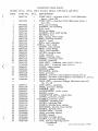
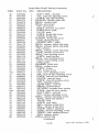
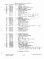
Parts Catalog (Roosa-Master Pumps)
262-B, 263-B Scrapers
545-B, 605-B Wheel Loaders
645-B Wheel Loaders
745-C Wheel Loaders
100-C, 150-C, 200-C Graders
0-2
0-2
0-2
0-2
1-1
1-1
1-2
1-3
1-5
1-6
1-7
1-7
1-8
2-1
3-1
4-1
4-1
4-1
4-2
5-1
6-1
6-1
6-4
6-6
7-1
7-2
8-1
8-1
8-4
9-1
9 1
-
9-1
9-3
9-3
9-4,5,6
10-1
11-1
11-1
11-3
11-4
12-2
12-6
12-12,18
12-24
12-30
NOTICE
CONSULT FIAT-ALLIS DEALER FOR OTHER
SERVICE MANUALS AVAILABLE FOR YOUR
UNIT . SEE TECHNICAL PUBLICATIONS INDEX
70658800 FOR ALL AVAILABLE PUBLICATIONS.
Study SAFETY RULES in the front of this manual thoroughly for the protection of machine and safety of personnel.
SERVICE MANUAL
(Revised January 1979)
0-1
FORM 73112988
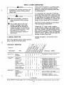
GENERAL
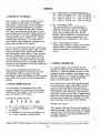
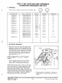
d. 3a - Abbreviation of Plunger Diameter.
25 - .250" (6.35mm) 33 - .330" (8.38mm)
27 - .270" (6.86mm) 35 - .350" (8.89mm)
29 - .290" (7.37mm) 37 - .370" (9.40mm)
31 - .310" (7.87mm) 39 - .390" (9.91mm)
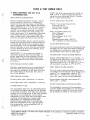
A.PURPOSE OF THE MANUAL
This manual is expressly intended to provide sufficient information for qualified
technicians, experienced in diesel engines
and diesel injection equipment, to disassemble and reassemble the Roosa Master
DM Type Fuel Injection Pump and to make
such adjustments and parts replacements as
may be needed. It is recommended that an
inexperienced person refrain from making
adjustments and repairs, as such action
may result in very extensive damage to the
pump and possibly to the engine .
e . JN - Accessory Code .
The code pertains to combinations of
special accessories such as electrical
shut-off, automatic advance, variable
speed droop adjustment, etc. See the
proper manual section for operation and
construction of these accessories. Include this in any reference to the pump.
No service should be performed on the pump
before making a careful study of this manual
and becoming familiar with the principles
and instructions which follow . Since several
critical adjustments of the injection pump
are required which cannot readily be made
on the engine, it is also necessary that the
service be performed in a facility equipped
with the proper special tools and an approved,
motorized test stand.
This manual completely describes the •
operating principles of the pump and most
accessories . Only through a thorough
knowledge of these principles can the serviceman locate and correct possible operational
defects .
C. GENERAL INFORMATION
In a diesel engine, air is drawn into the
cylinder through the intake valve and compressed. A metered quantity of fuel is then
injected into the cylinder, producing a combustible misture . This mixture ignites from
heat of compression, and the expanding
gases force the piston downward.
The function of a diesel fuel injection pump
is to accurately meter and deliver fuel to a
nozzle in each cylinder and to inject it at
high pressure into the combustion chamber
at precisely timed intervals . The extreme
precision necessary can well be appreciated
since this cycle must be repeated thousands
of times per minute with virtually no variation in timing or amount of fuel injected.
B. MODEL NUMBER SYSTEM
It is necessary to understand the model
number system for reference to the proper
sections of this manual covering operation
and maintenance of the pump.
EXAMPLE: Model Number
e
a
b
c d
DM
2 6 33 JN
1. 2580 - Specification Number.
Determines selection of parts and adjustments within a given accessory code .
Must be included in any reference to the
pump.
f
2580
MODEL DM PUMP
a. DM "M" version of "D" series pump.
b . 2 - Number of Plungers (2 or 4 plunger
versions) .
c . 6 - Number of Cylinders (available in 2,
3.4.6 and 8 cylinder configuration).
The models DM2 and DM4 are described as
opposed plunger, inlet metering, distributor
type pumps. The DM2 incorporates a single
pumping chamber, whereas the DM4 has 2
pumping chambers .
Study SAFETY RULES, pages I thru Ill, thoroughly for the protection of personal and machine safety.
0-2
General
The necessity for cost reduction is more
apparent in the small diesel engine where
the injection equipment represents a greater
percentage of the cost. Since the basic
model has but 100 odd parts, and only four
main rotating members, there is less chance
of part failure . Repairs are generally very
inexpensive . Today's small high output
engines have created a need for improved,
yet low cost injection equipment capable of
higher speed operation, quieter running and
lower exhaust emissions.
D. Increased diameter drive shaft with
larger tang drive . The drive shaft
is retained in the pump.
E Drive shaft roll pin for gear hub
alignment.
F . Spring-loaded, steel-backed, lip
type drive shaft seals.
2. Head and Rotor
A. Integral, angled discharge fittings.
B. Threaded transfer pump cap.
C. Shear groove in the rotor .
3. Governor
A. Weight retainer hub press fitted to
the rotor.
B. Cushioned weight retainer with
rubber compression members fully
enclosed within the assembly.
C. Low mass governor weights .
D. Larger diameter metering valve.
Precise distribution. between cylinders, inherent in the pump design, and the ability to
preset fuel flow eliminates lengthy periods
on the test stand. The pump is self lubricated (with the exception of the drive shaft
ball bearing), contains essentially the same
number of parts regardless of the number
of cylinders served, and operates in any
position.
4. Transfer Pump
A. Larger area inlet screen.
NEW DESIGN FEATURES
5. Automatic Advance
A . Advance circuit direct from transfer
pump.
B. Reed check valve.
This addition to the line of fuel injection
equipment incorporates many design
improvements, and has been durability
tested for more than 200,000 hours prior to
release for production.
New Design Features include:
1. Housing and Drive
A. Housing strengthened in the neck
area.
B. Rugged mounting flange.
Co Drive shaft supported by a heavy
duty ball bearing.
Study SAFETY RULES, pages 1 thru III, thoroughly for the protection of personal and machine safety.
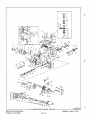
0-3
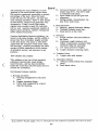
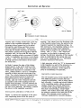
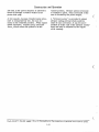
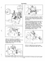
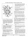
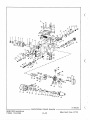
TOPIC 1 CONSTRUCTION AND OPERATION
FIG. 1.1
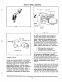
A. COMPONENTS AND FUNCTIONS
The main rotating components are the drive
shaft (1), distributor rotor (2), transfer
pump blades (3), governor (8).
It is necessary to become familiar with the
function of the main components to understand the basic operating principles of the
DM pump. See cutaway view (Fig. 1.1) for
construction details.
With reference to Fig. 1.1, the drive engages the distributor rotor in the hydraulic
head. The drive end of the DM2 rotor incorporates two pumping plungers and the
DM4 incorporates four
MAIN COMPONENTS
1.
2.
3.
4.
5.
6.
7.
8.
9.
10.
11.
Drive Shaft
Distributor Rotor
Transfer Pump Blades
Pumping Plungers
Internal Cam Ring
Hydraulic Head
Pressure Regulator Assembly
Governor
Automatic Advance
Housing
Metering Valve
The plungers are actuated toward each
other simultaneously by an internal cam
ring through rollers and shoes which are
carried in slots at the drive end of the rotor.
The number of cam lobes normally equals
the number of engine cylinders.
The transfer pump at the rear of the rotor
is of the positive displacement vane type
and is enclosed in the end cap. The end cap
also houses the fuel inlet strainer and
transfer pump pressure regulator. The
Study SAFETY RULES, pages I thru Ill, thoroughly for the protection of personal and machine safety
1-1
.
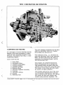
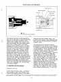
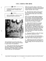
Construction and Operation
0 INLET
O TRANSFER PUMP PRESSURE
O HOUSING PRESSURE
■ INJECTION LINE PRESSURE
■ LUBE OIL
FIG . 1 .2
T -80638
through a positive linkage to the metering
valve . The metering valve can be closed to
shut off fuel through a solid linkage by an
independently operated shut-off lever .
face of the regulator assembly is compressed against the distributor rotor and
forms an end seal for the transfer pump.
The distributor rotor incorporates two
charging ports and a single axial bore with
one discharge port to serve all head outlets
to the injection lines. The weight retainer
hub is a shrink fit to the drive end of the
rotor .
The automatic advance is a hydraulic
mechanism which advances or retards the
beginning of fuel delivery from the pump.
B. FUEL FLOW
The hydraulic head contains the bore in
which the rotor revolves,the metering valve
bore, the charging ports and the head discharge fittings . The high pressure injection lines to the nozzles are fastened to
these discharge fittings .
The operating principles of the pump can be
understood more readily by following the
fuel circuit during a complete pump cycle
(Fig. 1.2). The fuel flow for the DM4 (Fig.
1.3) is basically the same as that of the
DM2 (Fig. 1.4) with the exception of the
charging of two additional plungers. Fuel is
drawn from the supply tank through filters
into the pump through the inlet filter screen
(1) by the vane type fuel transfer pump (2).
Some fuel is by-passed through the pressure
regulator assembly (3) to the suction side.
The DM pump contains its own mechanical
governor, capable of close speed regulation . The centrifugal force of the
weights in their retainer is transmitted
through a sleeve to the governor arm and
Study SAFETY RULES. pages I thru III, thoroughly for the protection of personal and machine safety.
1-2
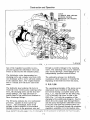
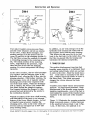
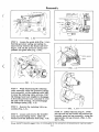
Construction and Operation
DM4
DM2
CAM ROLLER
CAM ROLLERCAM ROLLER
LEAF SPRING SCREW
SHOE
IWO
LEAF SPRING
SHOE
PLUNGER
SHOE PLUNGER
PLUNGER
SHIM
CHAMFER
INWARD
LEAF SPRING SCREW
CHAMFER
INWARD
FIG . 1.3
FIG . 1 .4
Fuel under transfer pump pressure flows
past the rotor retainers (4) into an annulus
on the rotor. It then flows through a connecting passage (5) in the head to the advance (6) and also to the charging circuit (7).
The fuel flows around the annulus (8) through
a connecting passage to the metering valve
(9). The radial position of the metering
valve, controlled by the governor, regulates the flow of fuel into the charging
annulus (10) which incorporates the charging ports.
As the rotor revolves, the two inlet passages
(11) register with the charging ports in the
hydraulic head, allowing fuel to flow into the
pumping chamber. With further rotation, the
inlet passages move out of registry and the
discharge port of the rotor registers with
one of the head outlets. While the discharge
port is opened, the rollers (12) contact the
cam lobes forcing the plungers together.
Fuel trapped between the plungers is then
pressurized and delivered by the nozzle to
the combustion chamber .
In addition, an air vent passage (13) in the
hydraulic head connects the outlet side of
the transfer pump with the pump housing.
This allows air and some fuel to be bled
back to the fuel tank via the return line. The
fuel thus by-passed fills the housing and
lubricates the internal components .
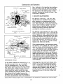
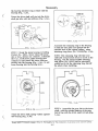
C. TRANSFER PUMP
The positive displacement vane type fuel
transfer pump consists of a stationary liner
and spring loaded blades which are carried
in slots in the rotor . Since the inside diameter of the liner is eccentric to the rotor
axis, rotation causes the blades to move in
the rotor slots. This blade movement
changes the volume between the blade
segments .
Transfer pump output volume and pressure
increase as pump speed increases . Since
displacement of the transfer pump exceeds
injection requirements, some of the fuel is
recirculated by means of the transfer pump
regulator to the inlet side of the transfer
pump.
With the exception of the drive shaft bearing,
self-lubrication of the pump is an inherent
feature of the Roosa Master design. As fuel
at transfer pump pressure reaches the
charging ports, slots on the rotor shank allow fuel and any entrapped air to flow into
pump housing cavity .
Figure 1.5 illustrates the pumping principle .
Blade movement causes a volume increase
in the quadrant between blade 1 and 2 (Fig.
1.5a). At this time, the quadrant is in
Study SAFETY RULES, pages I thru III, thoroughly for the protection of personal and machine safety.
1-3
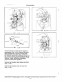
Construction and Operation
INLET SLOT
BLADE
LINER
ROTOR
a.
b.
c.
OUTLET GROOVE
■ INLET
$ TRANSFER PUMP PRESSURE
FIG . 1.5
running. Fuel output from the discharge side
registry with a kidney shaped slot in the top
of the transfer pump forces the piston in the
portion of the regulator assembly. The inregulator against the regulating spring. As
creasing volume causes fuel to be pulled
flow increases, the regulating spring is comthrough the inlet fitting and filter screen
pressed until the edge of the regulating
into the transfer pump liner Volume bepiston starts to uncover the pressure regtween the two blades continues to increase
ulating slot "A" (Fig. 1.6a). Since fuel
until blade 2 passes out of registry with the
pressure on the piston is opposed by the
regulator slot. At this point the rotor has
spring, the delivery pressure of the transfer
reached a position where movement of blades
1 and 2 is negligible and volume is not chang- pump is controlled by the spring rate and
size of the regulating slot "A". Therefore
ing (Fig. 1.5b). The fuel between the blades
pressure
increases with speed.
is being carried to the bottom of the transfer pump liner .
A high pressure relief slot "B" is incorporated
in the regulator as part of the pressure reAs blade 1 passes the edge of the kidney
gulating slot to prevent excessively high
shaped groove in the lower portion of the
transfer
pump pressure, if the engine or
regulator assembly (Fig. 1.5c), the liner,
pump
is
accidentally overspeeded.
whose inside diameter is eccentric to the
rotor, pushes blades 1 and 2 in a direction
opposite to their previous movement (Fig.
VISCOSITY COMPENSATION
1.5a). The volume between the blades is reduced and pressurized fuel is delivered
The DM transfer pump works equally well
through the groove of the regulator aswith different grades of diesel fuel and
sembly, past the rotor retainers and into
varying temperatures, both of which affect
an annulus on the rotor leading to the hyfuel viscosity. A unique and simple feature
draulic head passages . Volume between the
of the regulating system offsets pressure
blades continues to decrease, pressurizing
changes caused by viscosity difference.
the fuel in the quadrant, until blade 2 passes
Located in the spring adjusting plug is a
the groove in the regulator assembly.
thin plate incorporating a sharp-edged
orifice . The orifice allows fuel leakage past
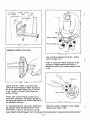
REGULATOR ASSEMBLY OPERATION
the piston to return to the inlet side of the
pump. Flow through a short orifice is
Figure 1.6 shows the operation of the presvirtually unaffected by viscosity changes.
sure regulating piston while the pump is
Study SAFETY RULES, pages I thru III, thoroughly for the protection of personal and machine safety.
1-4
Construction and Operation
REGULATING SLOT
REGULATING PISTON
REGULATING SPRING
INLET SIDE
REGULATOR
THIN PLATE
ORIFICE
M72;1r--
E\ %.r
r
SPRING ADJUSTING PLUG
DISCHARGE SIDE
a.
b.
INLET
2 TRANSFER PUMP PRESSURE
FIG . 1.6
The biasing pressure exerted against the
back side of the piston is determined by the
leakage past designed clearance of the
piston in the regulator bore and the pressure drop through the sharp edged orifice .
With cold or viscous fuels, very little
leakage occurs past the piston. The additional force on the back side of the piston
from the viscous fuel pressure is slight.
With hot or light fuels, leakage past the
piston increases. Fuel pressure in the
spring cavity increases also, since flow
through the orifice remains the same as
with cold or viscous fuel. The increased
fuel pressure assists the regulating spring
and moves the piston, reducing opened regulating slot area. This variation in piston
position compensates the leakage which
would occur with thin fuels and design pressures are maintained over a broad range
of viscosity changes.
pressure from the transfer pump, controlled by the opening of the metering valve,
flows into the pumping chamber forcing the
plungers apart.
The plungers move outward a distance
proportionate to the amount of fuel required
for injection on the following stroke. If only
a small quantity of fuel is admitted into the
pumping chamber, as at idling, the plungers
move out a short distance . Maximum
plunger travel and, consequently, maximum
fuel delivery is limited by a single leaf
spring (DM2) or two leaf springs (DM4)
which contact the edge of the roller shoes.
Only when the engine is operating at full
load will the plungers move to the most outward position. Note (Fig. 1.7) that while the
angled inlet passages in the rotor are in
registry with the ports in the charging
annulus, the rotor discharge port is not in
registry with a head outlet. Note also that
the rollers are off the cam lobes. Compare
their relative positions (Fig. 1.7 and 1.8).
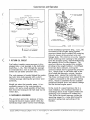
D. CHARGING AND DISCHARGING
CHARGING CYCLE
As the rotor revolves, (Fig. 1.7) the two
inlet passages in the rotor register with
ports of the charging annulus. Fuel under
Study SAFETY RULES, pages I thru Ill, thoroughly for the protection of personal and machine safety.
1-5
Construction and Operation
line . Delivery to the injection line continues
until the rollers pass the inner-most point
on the cam lobe and begin to move outward.
The pressure in the axial passage is then
reduced, allowing the nozzle to close. This
is the end of injection.
METERING VALVE
CHARGING ANNULUS
ANNULUS IN HYDRAULIC
HEAD
I
0.ity
SHOE
PLUNGER
CHAMBER
DISTRIBUTOR ROTOR
trait
ww,4
121i04 4%;(4
eff._
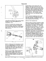
E. DELIVERY VALVE FUNCTION
1110
The delivery valve (Fig. 1.9a and 1.9b),
rapidly decreases injection line pressure
after injection to a predetermined value
lower than that of the nozzle closing pressure. This reduction in pressure causes the
nozzle valve to return rapidly to its seat,
achieving sharp delivery cut-off and preventing improperly atomized fuel from
entering the combustion chamber.
Pik 161►r4;.4FAI
l OWN
f/,
CAM WirefiC
LEAF SPRING
INLET PASSAGES
ROLLER BETWEEN CAM LOBE
TRANSFER PUMP
■
The delivery valve operates in a bore in the
center of the distributor rotor. Note that the
valve requires no seat - only a stop to limit
travel. Sealing is accomplished by the close
clearance between valve and bore into which
it fits. Since the same delivery valve performs the function of retraction for each injection line, the result is a smooth running
engine at all loads and speeds.
TRANSFER PUMP PRESSURE
FIG. 1.7
DISTRIBUTOR ROTOR
DISCHARGE FITTING
HEAD OUTLET
CAM
TO NOZZLE
When injection starts, fuel pressure moves
the delivery valve slightly out of its bore and
adds the volume of its displacement, section
"A", to the delivery valve spring chamber.
Since the discharge port is already opened to
a head outlet, the retraction volume and
plunger displacement volume are delivered
under high pressure to the nozzle. Delivery
ends when the pressure on the plunger side
of the delivery valve is quickly reduced, due
to the cam rollers passing the highest point
on the cam lobe which allows the plunger to
move outward.
DISCHARGE
etiiiirmamm iRT
1417141341
CHAMBER
)1149
LEAF
SPRING
PLUNGER
II
A..,
Imme P%sla
i>
SHOE
ROLLER
CONTACTS
CAM LOBE
DELIVERY VALVE
DISCHARGE PASSAGE
■
INJECTION LINE PRESSURE
FIG . 1.8
DISCHARGE CYCLE
As the rotor continues to revolve (Fig. 1.8),
the inlet passages move out of registry
with the charging ports . The rotor discharge port opens to one of the head outlets.
The rollers then contact the cam lobes and
injection begins. Further rotation of the
rotor moves the rollers up the cam lobe
ramps pushing the plungers inward. During
this stroke the fuel trapped between the
plungers flows through the axial passage of
the rotor and discharge port to the injection
Following this, the rotor port closes completely and a residual injection line pressure is maintained. Note that the delivery
valve is only required to seal while the discharged port is opened. Once the port is
closed, residual line pressures are maintained by the seal of the close fitting head
and rotor.
Study SAFETY RULES, pages I thru III, thoroughly for the protection of personal and machine safety.
1-6
Construction and Operation
AIR VENT PASSAGE TO GOVERNOR
LINKAGE COMPARTMENT
DISCHARGE PORT
DELIVERY VALVE
DELIVERY VALVE SPRING
DISCHARGE PASSAGE
DELIVERY VALVE STOP
DELIVERY VALVE
SCREW
DISTRIBUTOR
ROTOR
DELIVERY VALVE OPEN
A
INJECTION LINE
PRESSURE
RESIDUAL LINE
/ PRESSURE
HOUSING PRESSURE
ZI TRANSFER PUMP PRESSURE
DELIVERY VALVE CLOSED
FIG. 1.10
8
In the mechanical governor (Fig. 1.11), the
movement of the weights acting against
governor thrust sleeve rotates the metering
valve by means of the governor arm and
linkage hook. This rotation varies the registry
of the metering valve opening to the passage
from the transfer pump, thereby controlling
the quantity of fuel to the plungers . The
governor derives its energy from weights
pivoting in the weight retainer. Centrifugal
force tips them outward, moving the
governor thrust sleeve against the governor
arm, which pivots on the knife edge of the
pivot shaft and through a simple, positive
linkage hook, rotates the metering valve .
The force on the governor arm caused by the
weights is balanced by the governor spring
force, which is controlled by the manually
positioned throttle lever and vehicle linkage
for the desired engine speed.
IN INJECTION LINE PRESSURE
0 RESIDUAL LINE PRESSURE
FIG. 1.9
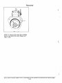
F. RETURN OIL CIRCUIT
Fuel under transfer pump pressure is discharged into a vent passage in the hydraulic
head (Fig. 1.10). Flow through the passage
is restricted by a wire to prevent excessive
return oil and undue pressure loss.
The vent passage is located behind the metering valve bore and connects with a short
vertical passage entering the governor compartment.
Should air enter the transfer pump, it immediately passes to the vent passage as
shown. Air and a small quantity of fuel then
flow from the housing to the fuel tank via the
return line .
In the event of a speed increase due to a
load reduction, the resultant increase in
centrifugal force of the weights rotates the
metering valve clockwise to reduce fuel.
This limits the speed increase (within the
operating range) to a value determined by
governor spring rate and setting of the
throttle .
G. MECHANICAL GOVERNOR
The governor serves the purpose of maintaining the desired engine speed within the
operating range under various load settings.
Study SAFETY RULES, pages I thru III, thoroughly for the protection of personal and machine safety
1-7
Construction and Operation
LINKAGE HOOK
\'X
GOVERNOR ARM
WEIGHT
GOV ERr)1\
ING
)
•
j
4,1f, OTTLE SHAFT
' I
PIVOT SHAFT
LOW IDLE SPRING
THRUST SLEEVE
WEIGHT RETAINER
METERING VALVE
•
FIG. 1.11
When the load on the engine is increased,
the speed tends to reduce . The lower speed
reduces the force generated by the weights
permitting the spring force to rotate the
metering valve in a counter-clockwise
direction to increase fuel. The speed of the
engine at any point within the operating range
is dependent upon the combination of load on
the engine and the governor spring rate and
setting as established by the throttle position.
A light idle spring is provided for more
sensitive regulation when weight energy is
low in the low end of the speed range . The
limits of throttle travel are set by adjusting
screws for proper low idle and high idle
positions.
A light tension spring takes up any slack in
the linkage joints and also allows the shut-
off mechanism to close the metering valve
without having to overcome the governor
spring force. Only a very light force is required to rotate the metering valve to the
closed position.
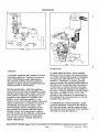
H. AUTOMATIC ADVANCE (Speed Advance)
The Roosa Master design permits the use of
a simple, direct acting hydraulic mechanism
powered by fuel pressure from the transfer
pump, to rotate the cam and vary delivery
timing. The advance mechanism advances or
retards start of fuel delivery in response to
engine speed changes. In most injection
systems, the actual beginning of delivery of
fuel at the nozzle will start later (in engine
degrees of rotation) as the speed increases.
Study SAFETY RULES, pages I thru ill, thoroughly for the protection of personal.and machine safety.
(Revised January 1981)
1-8
Construction and Operation
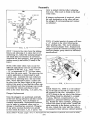
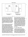
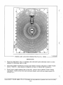
SPEED ADVANCE OPERATION
ADVANCE DIRECTION
CAM
END OF INJECTION TIMING VS. ENGINE SPEED
BTDC
ROTOR
ROTATION
6°—
DISTRIBUTOR ROTOR
2 50..,
U.J
U.J
Ful I
16°
Advance
)-•
12° -
.01111E■
-J
U-
—70 co
‘;
V)
c,1*.4‘
80.
ANNULUS
U.J
—60 cr
0_
—502
C.7
PISTON HOLE PLUG
Lu
4°
Full Retard
40
z
PASSAGE
z
600
HEAD LOCATING SCREW
a.
LL
w TDC
HYDRAULIC HEAD
E/)
—80
ca_
—
90
1200
1800
2400
3000
ENGINE SPEED (RPM)
ADVANCE PISTON
3 TRANSFER PUMP PRESSURE
FIG. 1.13
FIG. 1.12 a
piston is in its most effective position to
produce optimum power with minimum
specific fuel consumption and minimum
smoke.
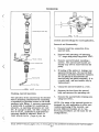
ADVANCE DIRECTION
The advance piston, located in a bore in the
housing, engages the cam through the advance pin and moves the cam (when fuel
pressure moves the piston) opposite to the
direction of rotor rotation (Fig. 1.12 a, Fig.
1.12 b ). Fuel under transfer pump pressure is fed through a drilled passage in the
hydraulic head which registers with the bore
of the head locating screw . Fuel is then
directed through a groove in the head locating screw to an annulus in the piston hole
plug. It enters a port in the piston hole plug
leading to the reed check valve . Increasing
transfer pump pressure forces fuel past the
valve to the advance piston. Fuel pressure
against the piston must overcome the
opposing spring force plus the dynamic injection loading on the cam in order to
change the cam position. The reed check
valve prevents the normal tendency of the
cam to return to the retard position during
injection by trapping the fuel in the piston
chamber. When engine speed decreases,
the hydraulic pressure is reduced and the
spring returns the cam to a retarded position in proportion to the reduction of speed.
CAM
0 TRANSFER PUMP PRESSURE
DISTRIBUTOR ROTOR
HOUSING
PISTON HOLE PLUG
TRIMMER SCREW
OWWAYREED VALVE
TRANSFER PUMP
PRESSURE
1
■
iii..
7111161117 1111/1/
ADVANCE SPRING
BLEED ORIFICE
PORT
TO REED VALVE
ADVANCE PISTON
ADVANCE PIN
FIG. 1.12b
Compensating this inherent "increasing injection lag" will often improve the high
speed performance of the engine . Starting
delivery of fuel to the nozzle earlier when
the engine is operating at higher speed insures that combustion takes place when the
Study SAFETY RULES, pages I thru Ill, thoroughly for the protection of personal and machine safety.
1-9
Construction and Operation
The fuel in the piston chamber is allowed to
bleed off through a control orifice in the
piston hole plug.
vanced position. Advance piston movement
is related to speed. Total movement of the
cam is limited by the piston length.
At low speeds, because transfer pump pressure is comparatively low, the cam remains in the retarded position . When engine
speed increases, transfer pump pressure
rises, which moves the piston to an ad-
A "trimmer screw" is provided to adjust
advance spring preload which controls
start of cam movement. It can be incorporated at either side of the advance mechanism and may be adjusted on the engine
while running.
Study SAFETY RULES, pages I thru ill, thoroughly for the protection of personal and machine safety.
1-10
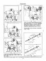
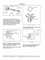
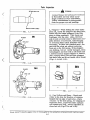
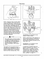
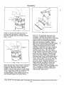
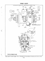
TOPIC 2 REMOVAL FROM ENGINE
A DANGER
NOTE: Do not steam clean or wash down
while the engine is operating. Severe damage
to the pump may occur if its temperature is
changed radically while running.
Extinguish all smoking materials and
open flames before working around
diesel fuel.
A
B Shut off the fuel supply and disconnect
inlet and return lines from their fittings .
Loosen injection tubing nuts at the nozzles
and pump.
WARNING
Never use gasoline, solvent or other
flammable fluids to clean parts.
NOTE: In removing the injection tubing nut
from the pump, hold the discharge fitting
with a wrench to prevent loosening from the
hydraulic head. Immediately after the lines
are removed, all pump, nozzles and line
openings should be capped or plugged.
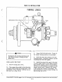
C. Check TEST STAND DATA ( Topic 9)
for proper timing position of crankshaft.
Bar the engine in correct direction of
rotation until the engine timing mark is indexed and the No. 1 cylinder is at the end of
the compression stroke . Remove the timing
line cover from the outboard side of the
pump. Timing line on the governor weight
retainer hub should be directly opposite the
line on the cam.
D. Disconnect throttle and shut-off linkage
and electrical connections if used.
FIG. 2.1
E . In most cases it will be necessary to
remove the pump drive gear from the hub or
drive shaft. Refer to the engine manual.
T-80627
F . Support the pump with one hand and remove the mounting stud nuts and washers on
the pump flange. Remove the pump from the
engine.
This procedure for removal of the pump
from the engine should be followed in detail
to assure ease of re-installation.
A . Clean and wash down the pump, fittings
and all connections with non-flammable,
non-toxic, commercial solvent to eliminate
the possibility of contamination entering the
system when lines are disconnected.
Study SAFETY RULES, pages I thru Ill, thoroughly for the protection of personal and machine safety
2-1
A DANGER
TOPIC 3 DISASSEMBLY
STEP 1 Remove the pump flange seal
from the housing (Fig. 3.1).
Extinguish all smoking materials and
open flames before working around
diesel fuel.
A
WARNING
A Never use gasoline, solvent or other
flammable fluids to clean parts.
A Wear safety glasses with side shields
or goggles when using compressed
air for cleaning to reduce the danger
of personal injury from flying particals. Limit the pressure to 30 psi
(2.1 kg/cm2) according to OSHA requirements.
PUMP FLANGE SEAL
Study the Manual first. Before commencing
the disassembly of the pump, cover inlet and
outlet holes, remove all external grease and
dirt by washing the unit with non-flammable,
non-toxic commercial solvent and blowing
it off with filtered, compressed air . It must
be constantly kept in mind that dirt, dust,
and foreign matter are the greatest enemies
of the fuel injection pump. As an added precaution to prevent dirt from entering the fuel
system while servicing the pump, it is
essential that a clean work space, clean
tools, and clean hands be used.
NOTE: All seals and gaskets should be discarded during disassembly.
A clean pan should be available in which the
parts may be placed upon disassembly, and
a pan of clean fuel oil must be available in
which the parts may be flushed. It is
recommended that these by deep drawn pans
which rounded corners to lessen the chances
of dirt pockets .
STEP 2 Mount the pump in holding Fixture
No. 19965. Never clamp the pump in a vise,
always use a fixture. Remove all lead
plumb seal wires. Unscrew the three cover
hold-down screws (Fig. 3.2a). Remove the
governor control cover and cover gasket
(Fig. 3.2b).
It is necessary for assembly to lubricate
parts with clean diesel fuel. Make sure
that all smoking materials are extinguished
and no open flames and sparks are near.
Place all parts prior to assembly in a
closed container of clean diesel fuel for
lubrication.
111
FIG. 3 .2 a
Study SAFETY RULES, pages I thru III, thoroughly for the protection of personal and machine safety.
3-1
Disassembly
GASKET
CONTROL COVER
(1
111111/11/1111111111/0111%...
-
FIG. 3.4
FIG. 3.2b
THROTTLE SHAFT
LEVER KEY
FULL SHUT-OFF
POSITION
FIG . 3.5
FIG . 3.3
STEP 5 Withdraw the throttle shaft assembly, and throttle shaft lever from the
shut-off lever assembly (Fig. 3.5). To aid
in correct reassembly, note the position of
the throttle shaft lever key in relationship
to the groove of the throttle shaft assembly.
STEP 3 Remove the shut-off cam by rotating the shut-off lever to the full run
(W .0 .T .) position. Place tool No. 20992,
with tab beneath the shorter leg of the shutoff shaft and pry gently, sliding the cam off
the shaft assembly (Fig. 3.3). Discard the
shut-off cam.
OS"
STEP 4
Remove the throttle shaft retainer clip by rotating the throttle lever to
the full run (W.0 .T .) position. Place tool
No. 20992, with tab beneath the shorter leg
of the retainer clip, on the throttle shaft
and pry gently, sliding the clip off the shaft
assembly. (Fig. 3.4) discard the retainer
clip.
GUIDE STUD
FIG. 3.6a
Study SAFETY RULES, pages I thru-Ill, thoroughly for the protection of personal and machine safety
3-2
Disassembly
GOVERNOR SPRING G COMPONENTS
■
/0 AIROV 11
'a
411411
ji
GUIDE STUD
io
METERING VALVE ARM
SPRING
CS)
0
111=
"Ow
FIG . 3.6b
FIG. 3.8
STEP 6 Loosen the guide stud (Fig. 3.6a).
Hold the governor spring and spring retainer firmly between the thumb and forefinger. Lift out the governor spring components and guide stud (Fig. 3.6b).
PLATE & WASHER
LINKAGE HOOK
SCREW
FIG. 3.7
STEP 7 While depressing the metering
valve assembly raise the governor linkage
hook assembly, at the metering valve end,
to clear the metering valve arm pin. Pull
the linkage hook back slightly to disengage
it from the governor arm and place it over
the side of the housing. Do not disengage
the linkage spring (Fig. 3.7).
STEP 8 Remove the metering valve assembly (Fig. 3.8).
STEP 10 Install end cap plug No. 20549
into the end cap and loosen and remove the
transfer pump end cap assembly, using the
appropriate end cap wrench. (Fig. 3.10a
and 3.10b).
STEP 9 Loosen and remove the transfer
pump end cap locking screw, plate and
washer from the hydraulic head (Fig. 3.9).
Study SAFETY RULES, pages I thru Ill, thoroughly for the protection of personal .and machine safety
3-3
Disassembly
END CAP ASSEMBLY
ROLLP IN
/ . REGULATOR ASSY .
/ PISTON
PISTON SEAL
PLUG ASSY .
4fterceri /
SCREEN SEAL /
Z
SPRING /
FIG . 3.10c
Disassemble the transfer pump regulator
components (Fig. 3.10c). Remove the inlet
filter screen seal. Remove the end plate
adjusting plug assembly with a 5/32" hex
key wrench. Shake the regulating spring and
piston out of the regulator assembly. Using
Tool No. 13301 remove the regulating
piston seal from the regulator.
FIG . 3.10e
Remove the transfer pump blades and liner
(Fig. 3.10d).
Remove the transfer pump end cap seal
(Fig. 3.10e).
Study SAFETY RULES, pages I thru III, thoroughly for the protection of personal and machtne safety.
3-4
Disassembly
HEAD LOCKING SCREWS
ADVANCE PLUG
FIG. 3.11a
14490
STEP 12 Loosen and remove the advance
screw hole plug using Tool No. 14490
(Fig. 3.12a and 3.12b).
STEP 11 Loosen the head locking screws
and remove one screw (Fig. 3.11a).
HEAD LOCATING
SCREW
FIG.
FIG. 3.11b
Invert the pump and holding fixture as a
unit in the vise. Loosen and remove the
head locating screw (Fig. 3.11b and 3.11c).
.12b
EXTRACTOR NO. 13301
HEAD LOCATING SCREW
ADVANCE PIN
FIG. 3.12c
Insert Extractor No. 13301 into the hole in
the advance pin and extract the pin (Fig.
3.12c).
—
FIG. 3.11e
Study SAFETY RULES, pages I thru Ill, thoroughly for the protection of personal and machine safety
3-5
Disassembly
FIG . 3.12 g
NOTE: The sides of the housing just above
the advance bear a "C" or "CC" marking to
denote pump rotation. The power side of
the piston is located on the "C" side of a
clockwise rotating pump and vice versa.
Disassemble the auto advance components
(Fig. 3.12h).
PISTON RING
C°.
PISTON RING SEA\
ADVANCE PISTON
W
SEAL
\ PLUG
REED VALVE
SEAL
SPRING
GUIDE
PISTON HOLE PLUG
PLUG
ADJUSTING SCREW
PLUG
SEAL
REED VALVE SCREWS
7)43
RING
SPRING
NUT
PISTON HOLE PLUG
PISTON RING
10
02
SEAL
SEAL
t
REED VALVE
WASHER
FIG . 3.12f
Loosen and remove the advance plug and
power piston plug (Fig. 3.12d, 3.12e, 3.12f
and 3.12g).
ADJUSTING SCREW
PISTON RING SEAL
ADVANCE PISTON
FIG. 3.12h
Study SAFETY RULES, pages I thru Ill, thoroughly for the protection of personal and machine safety.
3-6
Disassembly
HYDRAULIC HEAD ASSEMBLY
THRUST WASHER
WEIGHT
THRUST SLEEVE
TILT DOWNWARD
FIG 3.14
FIG . 3.13 a
STEP 14 To disassemble the governor,
invert the hydraulic head and let the
weights, governor thrust sleeve and
washer fall into your hand (Fig. 3.14).
Place head and rotor assembly on top of
fixture No. 19965.
STEP 13 Return the pump and holding fixture as a unit to its initial position in the
vise with the rear of the hydraulic head
tilted slightly downward. Remove the remaining head locking screw. Grasp the hydraulic head assembly firmly in both hands
and withdraw with a slight rotary motion
(Fig. 3.13a and 3.13b).
NOTE: Use caution so as not to drop the
governor weights .
WEIGHTS
HYDRAULIC HEAD
ASSEMBLY
N
FIG. 3.15a
N
STEP 15 Loosen and remove one pivot
shaft retainer nut and seal (Fig. 3.15a).
FIG. 3.13b
Study SAFETY RULES, pages I thru III, thoroughly for the protection of personal and machine safety.
3-7
Disassembly
GOVERNOR ARM
PIVOT SHAFT._
SEAL
PIVOT SHAFT NUT
RETAINING RING
FIG. 3.16c
C
Remove the retaining ring using retaining
ring pliers (No. 20043)(Fig. 3.16c).
FIG . 3.15 b
The governor arm pivot shaft, arm and
linkage hook assembly may now be removed (Fig. 3.15b).
NOTE: This retaining ring is under considerable compression force. Use only the
recommended retaining ring pliers (No.
20043), and be extremely careful not to
let the retaining ring slip off the pliers
when removing.
HUB RETAINING
NUT & WASHER
SPRING WASHER
FIG . 3.16a
STEP 16 Install Tool No. 19928 on the
gear hub, loosen and remove the hub regaining nut and washer (Fig. 3.16a).
Remove the drive shaft spring washer
(Fig. 3.16d).
GEAR HUB
1(1924
Install Gear Hub Puller Tool No. 19924
(Fig. 3.16b) and remove the gear hub.
Study SAFETY RULES, pages I thru III, thoroughly for the protection of personal and machine safety.
3-8
Disassembly
DRIVE SHAFT
FIG. 3.16e
Remove the drive shaft roll pin using
diagonal pliers (Fig. 3.17b) . To remove the
roll pin if it is broken use a 5/64" easy out
extractor or a 3/32" carbide tipped drill.
The drive shaft assembly may not be removed from the housing (Fig. 3.16e).
7) SHAFT
DRIVE
BEARING SHOULDER RING
ARBOR PRESS
ROLL PIN
BEARING
DRIVE SHAFT
BALL BEARING
4
18332
20044
FIG . 3.17c
Place drive shaft on an arbor press and
press on the threaded end of the drive shaft
against the ball bearing. Support the bearing . inner race with Tool No. 18332 to prevent bearing damage (Fig. 3.17c).
FIG. 3.17a
NOTE: Step 17 is only necessary if damage
has occured to the drive shaft, roll pin or
ball bearing.
STEP 17 Remove the bearing shoulder
ring using retaining ring pliers (No 20044)
(Fig. 3.17a). It may be necessary to press
off the ball bearing assembly slightly in
order to do this.
Study SAFETY RULES, pages I thru III, thoroughly for the protection of personal and machine safety.
3-9
Disassembly
RETAINING
RING
SEAL
GO
GO
CO
CO
FIG 3.18 a
STEP 18 Remove the seal retaining ring
from the housing (Fig. 3.18a).
ARBOR PRESS
FIG . 3.19
V
20268
ROTOR RETAINERS
FIG . 3.18b
Place the inner portion of tool No. 13375
onto tool No. 20268 and press (From the
front of the housing) the two drive shaft
seals from the housing using an arbor press
(Fig. 3.18b).
FIG . 3.20
NOTE: Discard these seals, as they should
not be reused.
STEP 20 Remove the rotor retainers
(Fig. 3.20).
STEP 19 Lift the liner locating ring from
the rotor retainers (Fig. 3.19). (The early
design transfer pump components used a
locating ring without a split. Remove this
solid ring by inserting two small rods or
hex-key wrenches into the two holes in the
ring and prying outward).
Study SAFETY RULES, pages I thru Ill, thoroughly for the protection of personal and machine safety.
3-10
Disassembly
CAM ROLLER
HYDRAULIC HEAD
DM2
SHOE
SEAL
PLUNGER
.f LEAF SPRING SCREW
SHIM
LEAF SPRING
FIG. 3.21c
DM 4
CAM ROOI ER
0
LEAF SPRING SCREW
O
SHOE
FIG. 3.21a
L EAF SPRING
CAM ROLLER
PI UNGER
1_,
SHOE
PI UNGER
CHAMFER
INWARD
CHAMFER
INWARD
FIG . 3.21b
STEP 21 Lift the head from the rotor
(Fig. 3.21a). Lift the cam ring from the
rotor (Fig. 3.21b).
FIG. 3.21d
Check and record roller-to-roller dimension
as instructed on page 5-6, Step 7, DM2 or
DM4. Compare this dimension with that
called for on the pump specification. Remove roller shoes and plungers (Fig. 3.21c
and 3.21d). Use brass Tool No. 13301 to
push pumping plungers from their bore .
Handle all parts carefully with clean hands
wet with fuel oil or calibrating oil. Avoid
handling the precision ground surface of the
rotor . Use a 5/32" hex key wrench to
loosen and remove the leaf spring adjusting
screw(s), leaf spring(s) and shims (if used)
from the rotor.
Study SAFETY RULES, pages I thru III, thoroughly for the protection of personal and machine safety
3-11
Disassembly
DELIVERY VALVE
WEIGHT RETAINER
STOP
(11/1100
ROTOR
K(fCtRf.
SPRING
ewef
SCREW
FIG. 3.21e
Loosen and remove delivery valve stop
screw using a 5/32" hex key wrench or 3/16"
hex key wrench (Fig. 3.21e). The delivery
valve stop and spring may now be removed.
If the delivery valve does not slide freely
from its bore, use extractor No. 13383.
Discard the delivery valve stop.
RUBBER CUSHION
FIG . 3.22.b
Remove weight retainer and rubber cushions
from the hub (Fig. 3.22b).
RETAINING RING
13337
METERING VALVE
ARM
CUSHION RETAINER
SPRING
FIG . 3.22a
FIG .3.23
STEP 22 Remove the retaining rings and
cushion retainers from the governor weight
retainer assembly (Fig. 3.22a).
NOTE: Discard the retaining rings since they
should not be reused.
STEP 23 Remove the metering valve from
the arm assembly with retaining ring
pliers (No. 13337) (Fig. 3.23).
Study SAFETY RULES, pages 1 thru III, thoroughly for the protection of personal and machine safety
3-12
.
A DANGER
TOPIC 4 PARTS INSPECTION
Parts must be washed in a non-flammable
non-toxic, commercial solvent and then
placed in a clean pan containing fresh fuel
or calibrating oil.
Extinguish all smoking materials and
open flames before working around
diesel fuel.
,
use gasoline, solvent or
A Never
other flammable fluids to clean
It is necessary for assembly to lubricate
parts with clean diesel fuel. Make sure that
all smoking materials are extinguished and
no open flames and sparks are near. Place
all parts prior to assembly in a closed container of clean diesel fuel for lubrication.
A Wear safety glasses with side
Examine all parts carefully in accordance
with instructions which follow:
A WARNING
parts.
shields or goggles when using
compressed air for cleaning to
reduce the danger of personal injury from flying particles. Limit
the pressure to 30 psi (2.1
kg/cm2) according to OSHA requirements.
Discard all "0" rings, seals, gaskets,
weight retainer cushions and weight retaining rings . Replace with appropriate gasket
kits. Examine all springs for fretting, wear,
distortion or breakage. Clean and carefully
check all bores, grooves and seal seats for
damage or wear of any kind.
Replace damaged or worn parts as necessary.
A. GENERAL INSPECTION
Dirt is the greatest enemy of fuel injection
pump. Keep the work area clean.
B.DETAILED INSPECTION
Examine For:
Housing & Drive
Hydraulic Head
& Rotor
Transfer Pump
PART
SPECIFICALLY INSPECT:
Housing
Drive Shaft
Ball Bearing
See Supplementary Inspection 1, Page 4.2
X
Hydraulic Head
Vent Wire
Discharge Fittings
X
X
X
X X
X
X
X
X
Distributor Rotor
Delivery Valve
Plungers
Cam Rollers & Shoes
Leaf Spring(s) & Screw(s)
Cam
Governor Weight Retainer
X
X
X
X
X
X
X
X
X X X X
X X X X
X
X
X
X X X X
X
X
X
X
X
X
Governor Weights
Governor Thrust Washer
Governor Thrust Sleeve
X
X
X
End Cap
Inlet Screen
End Plate Adj. Plug
Regulating Piston
Regulator
'
Blades
Liner
Rotor Retainers
X
X
X
X
X
X
X
X X X
X
X
XXXXX XX X
PART GROUP
X
X
X
X
X
X
X
X
X
X
X
X
X
X X
x x x x
x x
x x
x x
X See Supplementary Inspection 2, Page 4.2
Inside diameter of discharge fittings,
sealing area for wear, nicks & scores
X See Supplementary Inspection 3, Page 4.2
X See Supplementary Inspection 4, Page 4.2
X See Supplementary Inspection 5, Page 4.2
X See Supplementary Inspection 6, Page 4.3
See Supplementary Inspection 7, Page 4.3
See Supplementary Inspection 8, Page 4.3
Where weights pivot in retainer socket, also "E"
ring area for wear, loose pins
X See Supplementary Inspection 9, Page 4.3
Contact areas for excessive wear
Points of contact with governor arm for excessive
wear
Screen and soldered area for breakage
Tightness in regulator, plugged orifice, loose plate
X
Inside diameter of regulator
See Supplementary Inspection 10, Page 4.3
Inside diameter in high pressure area for wear
( Continued)
Study SAFETY RULES, pages I thru Ill, thoroughly for the protection of personal and machine safety.
4-1
Parts Inspection
PART GROUP
Governor
PART
SPECIFICALLY INSPECT:
Pivot Shaft
Arm
X
X
X
X
X
X
Metering. Valve
Metering Valve Arm
X
X
X
X
X
X
X
X
Linkage
Linkage Hook
X
X
X
X
Advance
Piston
Pin
Reed Valve
Plugs
X
X
X
X
X
X
X
X
X
X
X
X
X
X
X
X
X
X
X
X
X
X
X
X
Chipped or worn knife edge
Points of contact with thrust sleeve & pivot
shaft for excessive wear
See Supplementary Inspection 11, Page 4.4
See Supplementary Inspection 11, Page 4.4
X
Metering valve pin hole
X
Bore for excessive wear
DRIVE TANG
METERING VALVE HOLE
DRIVE TANG
HYDRAULIC HEAD
.430" MIN.
30" MIN.
VENT WIRE
FIG. 4.1
C. SUPPLEMENTARY INSPECTION
FIG. 4.2
1. Drive Shaft - Measure the distance
across the flats of the drive tang which
must not be less than .430". The shaft
diameter in the drive shaft seal area must
be free of nicks and scratches for the seals
to function properly. Moderate shaft wear
from the seal lips is normal (Fig. 4.1).
3. Distributor Rotor - Examine the radii
contacted by the leaf spring(s) and the tang
slot for excessive wear. Check all slots,
charging and discharge ports for chipping
of edges or dirt, and the rotor shank for
major scratches. Slight erosion on the edge
of the discharge port is considered normal.
If damage or excessive wear is apparent,
the head and rotor must be replaced as a
matched unit. Final check for excessive
wear on the rotor should be performed on
the test stand by checking for minimum
cranking delivery.
2. Hydraulic Head - Check the vent wire in
the hydraulic head air bleed passage for
freedom of movement. If the wire is free,
flush the head and blow out all passages with
clean, dry air. If vent wire is stuck, remove and replace it after a thorough cleaning of the passage. Refer to the proper
specifications for the correct vent wire.
4. Delivery Valve - Inspect delivery valve
retraction cuff for chipping or erosion of
edges (Fig. 4.3).
NOTE: Do not immerse this head in solvent
for extended periods as sealant damage
will result (Fig. 4.2).
Study SAFETY RULES, pages I thru Ill, thoroughly for the protection of personal and machine safety.
4-2
Parts Inspection
RETRACTION CUFF
A WARNING
Lacquer thinner and acetone are extremely flammable and may cause an allergic reaction in some individuals.,
Follow manufacturer's recommendations for proper use and handling.
MUST BE SHARP EDGED
5. Plungers - While holding the rotor under
clean oil, insert the plungers into their bore
Insert only the longer plungers if the DM4
pump is being examined. With thumb and
forefinger over the shoe slots, tilt from
side to side several times to determine complete freedom of movement. Interchanging
or reversing their initial positions may be
necessary, as these are matched parts Repeat with the short set without removing
first set on the DM4 pump. If the plungers
are sticking, but not visibly damaged, clean
both plungers and bore with a soft brush and
a solvent such as lacquer thinner or acetone.
(See warning above) (Do not force plungers
into their bore and do not handle rotor shank)
(Figs. 4.4a and 4.4b).
FIG. 4.3
PLUNGER
DM2
SHOE SLOT
PLUNGER
13M4
SHOE SLOT
A7W
FIG. 4.5
6. Cam Rollers and Shoes - Check each
roller in its shoe for freedom of rotation.
Inspect the top edge of each shoe, where
retained by the leaf spring, for chipping or
excessive wear. Improved roller surfaces
will result from long, normal operation in
clean fuel oil (Figs 4.5a and 4.5b).
FIG. 4.4b
Study SAFETY RULES, pages I thru Ill, thoroughly for the protection of personal and machine safety.
4-3
Parts Inspection
DM2
DM4
FIG. 4.6
9. Governor Weights - Check pivot points
and toe) of all weights for excessive wear
(Fig. 4.8).
7. Leaf Spring (s) and Screw(s) - Check
for excessive wear at points where the
spring(s) contacts the radii on the rotor and
along the steps that retain the roller shoes .
Check the adjusting screw(s) for tightness in
the rotor (Figs. 4.6).
FIG . 4.7
FIG. 4.9
10. Transfer Pump Blades - Inspect with
the utmost care . Check for chipping on any
of the edges, including spring bore edges,
pitting, imbedded foreign particles or
scoring on the rounded ends . Determine
blade wear by measuring the length(0.538"
minimum). Inspect flat surfaces visually
for deep scores. If any discrepancies are
noted, replace both blade sets and springs
(Fig. 4.9).
8. Cam - Since only the working portions
of the lobes on the inside diameter are
ground, any tool marks between lobes
should not be considered as damage . The
mottled appearance of the cam is from heat
treatment rather than from operation. Carefully inspect the cam lobes and edges of all
flat surfaces. If there is evidence of spoiling or flaking out, replace with a new cam.
Improved cam lobe finish will result from
long, normal operation in clean fuel oil
(Fig. 4.7).
Study SAFETY RULES, pages I thru III, thoroughly for the protection of personal and machine safety.
4-4
Parts Inspection
11. Metering Valve and Arm - Check the
metering valve body for excessive wear .
Be sure the metering valve arm is well
seated and that there is no radial movement
of the arm on the valve . Check the metering
valve spring for distortion and the metering
valve arm pin for wear or looseness (Fig.
4.10).
FIG. 4.10
Study SAFETY RULES, pages I thru Ill, thoroughly for the protection of personal and machine safety.
4-5
,
A DANGER
TOPIC 5 REASSEMBLY
Extinguish all smoking materials and
open flames before working around
diesel fuel.
A
DRIVE SHAFT SEAL
SEAL LIP
WARNING
Never use gasoline, solvent or other
flammable fluids to clean parts.
)
All parts must be thoroughly flushed in
clean oil as they are being reassembled; do
not wipe oil or wipe dry. Cleanliness will
contribute to long life and trouble-free
operation. All seals and gaskets must be
replaced, whether visibly damaged or not.
Gasket kits are provided for this purpose.
Refer to PARTS CATALOG (Topic 12) for
gasket kit part numbers. Apply clean grease
sparingly to all seals to facilitate assembly
and to prevent cutting.
FIG. 5.1a
It is necessary for assembly to lubricate
parts with clean diesel fuel. Make sure that
all smoking materials are extinguished and
no open flames and sparks are near. Place
all parts prior to assembly in a closed container of clean diesel fuel for lubrication.
IMPORTANT: Refer to the Torque Value
Chart for proper tightening of all fasteners.
STEP 1 To install the drive shaft seals,
place the pump housing (flange end down) on
an arbor press. Apply a light coating of
lithium base grease to the housing seal bore
and the 0.D. of the seals prior to assembly.
If the housing seal bore is scored due to seal
removal, apply a light coating of Gasoila
sealing compound to the seal bore instead of
grease. Place a new seal, with the seal lip
facing the tool, on the short end of Tool No.
20268 (Fig. 5.1a). Press the seal into the
housing until the tool bottoms against the
housing (Fig. 5.1b ). Note: This seal must
not protrude into the housing cavity.
FIG. 5.1b
Invert the pump housing (flange end up) on
the arbor press. Place a new seal, with
seal lip facing the tool, on the short end of
Tool No. 20268 (Fig. 5.1c) and press the
seal into the flange end of the housing until
the tool bottoms (Fig. 5.1d).
Study SAFETY RULES, pages lthru Ill, thoroughly for the protection of personal and machine safety.
5-1
Reassembly
DRIVE SHAFT
N
e.
BEARING SHOULDER
RING
DRIVE SHAFT SEAL
GROOVE
FIG. 5,1c
ARBOR PRESS
FIG. 5.2a
ARBOR PRESS
DRIVE SHAFT
FIG. 5.1d
BEARING SHOULDER RING
FIG, 5.1e
FIG, 5.2b
Note the correct position of the seals, as
shown in Fig. 5.1e. Insert the seal retaining
ring into the groove in the housing seal bore .
PRESS DRIVE SHAFT ROLL PIN
STEP 2 Install the bearing shoulder ring in
the groove on the drive shaft using retaining
ring pliers (No. 20044) (Fig. 5.2a).
DRIVE SHAFT
Place the drive shaft into the bearing on an
arbor press with threaded end down.
Support the bearing inner race with Tool No.
18332. Press the shaft into the bearing until
FIG. 5.2c
Study SAFETY RULES, pages I thru Ill, thoroughly for the protection of personal and machine safety.
5-2
Reassembly
the bearing shoulder ring is flush with the
bearing (Fig. 502b).
RETAINING RING
Press the drive shaft roll pin into the drive
shaft pin hole until pin bottoms (Fig. 5.2c).
RETAINING RIND
PRESSED
AREA
SPRING
WASHER
RETAINING RING
OPEN ENDS,_
FIG. 5.3c
Assemble the retaining ring to the housing
so that the open ends are against the depressed area of the spring washer, using
retaining ring pliers (No. 20043)(Fig. 5.3c).
FIG, 5.3a
STEP 3 Mount the pump housing in holding
Fixture No. 19965,, Never clamp the pump
into a vise, always use a fixture. Lubricate
the 0.D. of the drive shaft bearing with
mineral oil and install the drive shaft assembly into the housing (Fig. 5.3a) Do not
force bearing into the housing bore.
NOTE: This retaining ring will take considerable compression force to insert in the
housing. Use the recommended retaining
ring pliers (No. 20043) and be extremely
careful not to let the retaining ring slip off
the pliers when installing.
SPRING
WASHER
GEAR HUB
DRIVE SHAFT
BEARING
0
•/
FIG . 5.4a
/
STEP 4 Assemble the gear hub to the drive
shaft, with the notched portion of the gear
hub in line with the drive shaft roll pin (Fig.
5.4a) .
FIG.5.3b
Place the drive shaft spring washer against
the bearing (Fig. 5.3b).
Study SAFETY RULES, pages I thru III, thoroughly for the protection of personal and machine safety.
5-3
HUB RETAINING
19928
NUT & WASHER
0
RUBBER CUSHIONS
WEIGHT RETAINER
FIG. 5.4b
REFERENCE TORQUE VALUE CHART
FIG. 5.5a
Line Location Indicator (Tool No. 20395)
shown on page 11-2
150
125
100
STEP 5 Place the rubber cushions on the
governor weight retainer pins and assemble the hub to the weight retainer (Fig.
5.5a).
75
50
25
0
0
25
50
RETAINER PIN
FIG. 5.4c
Install Tool No 19928 on the gear hub.
Place the hub retaining washer and nut on
the drive shaft and torque (Fig. 5.4b and
5.4c). Refer to Torque Value Chart for
proper torque .
CUSHION RETAINER
NOTE: The correct torque on this nut is
extremely important. Extensive damage to
the pump and engine may result if the nut is
not properly secured.
FIG. 5.5b
To mechanically time any pump, determine
the position of the timing line from Test
Stand Data ( Topic 9) and use the Timing
Place the cushion retainers on the weight
retainer pins (Fig., 5.5b).
Study SAFETY RULES, pages 1 thru Ill, thoroughly for the protection of personal and machine safety.
5-4
Reassembly
Install delivery valve spring and a new
delivery valve stop to the rotor bore. Installation of a used stop can result in leakage and low output at cranking speeds .Start
the delivery valve retaining screw into the
bore using the hex end of the delivery Extractor Tool No. 13383 or use a 3/16" hex
key wrench for a .250" delivery valve.
Tighten the screw to the specified torque
(Fig. 5.6).
RETAINER PIN,
RETAINING RING
•
K
NOTE: Excessive tightening of this screw
may cause seizure of the hydraulic head
and rotor assembly. Insufficient torque may
cause leaking and hard starting.
FIG. 5.5c
Assemble the retaining rings into the weight
retainer pin slots with Applicator (No.
20045)(Fig. 5.5c).
Delivery Valve Replacement
Delivery valves of various retraction values
are used for different applications . Correct
part numbers are found on individual pump
specifications. The letters "OV" etched on
the head of the rotor indicate a .001" oversize delivery valve bore A rotor so marked
must use a .001" oversize delivery valve.
The oversize valve is also identified by
blackening on both ends and in the groove on
the delivery valve shank. Oversized delivery
valves are intended to compensate for
manufacturing tolerances only and are not
to be used in a standard delivery valve bore .
Oversize valves are not standard stocked
parts of Fiat-Allis; and are obtainable only
by special order to your Fiat-Allis dealer.
NOTE: Do not distort the retaining rings .
Check for proper assembly by trying to
turn the retaining rings with a small bladed
screw driver. They should not move under
light pressure.
DELIVERY VALVE
STOP
ROTOR
SPRING
/
PLUG
DM2
1
FIG. 5.6
CAM ROLLER
SHOE
PLUNGER
STEP 6 Rinse the rotor thoroughly in clean
fuel oil or calibrating oil. Place the rotor
on top of holding Fixture No. 19965. Install
the delivery valve to its bore using Extractor Tool No. 13383. Make sure that it
operates freely in its bore
LE AF SPRING SCREW
NOTE; Do not mistake slight interference
of the retractor collet in the bore for
delivery valve sticking. If the valve is not
secured straight and tight in the retractor
collet, the collet diameter can drag in the
rotor bore.
SHIM
LEAF SPRING
FIG. 5.7a
Study SAFETY RULES, pages / thru III, thoroughly for the protection of personal and machine safety.
5-5
Reassembly
rotor is etched with the letter indicating
bore size . This mark is found on the head
of the rotor .
DM 4
CAM ROLLER
LEAF SPRING SCREW
If plunger replacement is required, check
the size designation on the rotor and use
the plunger of corresponding part number
as indicated .
SHOE
CAM ROLLER
LEAF SPRING
PLUNGER_
SHOE
SHIM
PLUNGER
r
Q
0
CHAMFER
INWARD
CHAMFER
INWARD
NOTE: A limited number of pumps will have
a "-2" etched on the rotor following the
letter grading code . This mark indicates a
.002" oversize plunger bore . Replacement
plungers should be ordered according to the
oversize plunger group shown on individual
specifications .
FIG. 5.7b
STEP 7 Remove the rotor from the holding
fixture and submerge it in clean fuel oil or
calibrating oil. Install the pumping plungers
and check them for freedom of movement.
Assemble the leaf spring(s), leaf spring adjusting screw(s) and shims (if used) to the
rotor .
NOTE: DM4 roller shoes vary in size for
different applications and are marked with
a number on the end, e.g., from "-20 to
- 10" in increments of "5". All four shoes
must bear the same mark. The shoe size for
a given application is determined by part
number only. Assemble the cam rollers to
the shoes by inserting from the end of the
shoe . Never attempt to press a roller into
its shoe from the outer edges, as the groove
width at this point is less than the roller outside diameter and shoe breakage may result.
Assemble the rollers and shoes to their
slots in the rotor head (Fig. 5.7a and 5.7b).
FIG. 5.7
DM2
Install Fixture No. 19969 in a vise (clamping on the flat) so that the air inlet hole is
not covered by the vise Assemble a 1/4"18 NPT fitting to the air inlet of the fixture .
This fitting should be attached to a supply
of clean, filtered, compressed air, regulated to a pressure between 40 and 100
psi. Handle the rotor carefully, holding the
rollers and shoes in their slots . Install the
rotor assembly to the fixture on the air inlet side . Rotate the rotor until the rollers
are pushed to their extreme outward position
Plunger Replacement:
Since the plungers are positioned centrally
in the bore during operation and their travel
is extremely short, wear of plungers is
virtually nonexistent . Replacement however,
may be made in instances where rust or
damage is handling has occurred. Plungers
of any given nominal diameter are graded
in four select fit sizes: A, B, C and D. The
Study SAFETY RULES, pages I thru Ill, thoroughly for the protection of personal and machine safety.
5-6
Reassembly
(shoes bottomed on the leaf spring) by the
air pressure . Using a 1" to 2" micrometer,
measure the roller-to-roller dimension
(Fig. 5.7c) (distance between the outer surfaces of the opposed cam rollers) and compare this with the specification. To set the
roller-to-roller dimension to the pump
specification, turn the leaf spring adjusting
screw inward (clockwise) to increase and
outward (counter-clockwise) to reduce the
roller-to-roller dimension.
NOTE: The roller-to-roller setting provides
a completely accurate maximum fuel adjustment and it should not differ from that
shown in the TEST STAND DATA ( Topic 9)
rotor assembly to the fixture on the air inlet side. Loosen the dial indicator retaining
screw and slide the indicator to its outer
limit . Rotate the rotor until the rollers are
pushed to their extreme outward position
(shoes bottomed on the leaf spring) by the
air pressure. Using a 1" to 2" micrometer,
measure the roller-to-roller dimensions
(Fig. 5.7d) (distance between the outer
surfaces of the opposed cam rollers) and
compare this with the specification. To set
the roller-to-roller dimension to the pump
specification, set the rollers, adjusting
each leaf spring alternately. Turn the leaf
spring adjusting screws inward (clockwise)
to increase and outward (counter-clockwise)
to reduce the roller-to-roller dimensions.
Since each roller shoe for a given cylinder
is controlled by a separate leaf spring, it
may be necessary to invert or interchange
leaf springs to obtain correct dimensions on
both sets of rollers. Roller settings of both
cylinders must be within .003" of each
other while maintaining the average rollerto-roller setting within the specification.
Check centrality of the rollers (to assure
that each one starts its pumping stroke at
the same time) as follows:
a.
Rotate the rotor until one roller is
aligned with the dial indicator plunger.
Slide the indicator inward until plunger
depresses it at least .010". Lock indicator retaining screw. "Zero" in indicator on high point of roller by rotating knurled dial.
b.
Rotate rotor (either direction) until the
next roller depresses dial indicator
plunger , Allowable centrality is plus
or minus .002" (total .004"). Before
making any correction, check and record centrality of all four rollers .
c.
If roller centrality is beyond specified
tolerance, rollers and/or shoes can be
interchanged. Recheck centrality after
each change. Be sure to recheck rollerto-roller dimension.
FIG. 5.7d
DM4
Install Fixture No. 19969 in a vise (clamping on the flat) so that the air inlet hole is
not covered by the vise . Assemble a 1/4"18 NPT fitting to the air inlet of the fixture .
This fitting should be adapted to a supply of
clean, filtered, compressed air regulated
to a pressure between 40 and 100 psi.
Handle the rotor carefully, holding the
rollers and shoes in their slots . Install the
NOTE: The roller-to-roller setting provides a completely accurate maximum fuel
adjustment and it should not differ from that
shown in the applicable specification.
Study SAFETY RULES, pages I thru Ill, thoroughly for the protection of personal and machine safety.
5-7
Reassembly
HYDRAULIC HEAD
FIG. 5.8b
STEP 8 When the roller-to-roller adjustment is completed, remove the rotor assembly from the fixture, making sure that
the cam rollers and shoes are not dislodged
from their slots . Thoroughly rinse the
rotor in clean fuel oil or calibrating oil and
place the rotor shank end up on top of Fixture No. 19965. Place the cam ring on top
of the rotor with the directional arrow indicating the opposite direction of pump
rotation (Fig. 5.8a). This is necessary
since pump rotation is always expressed as
viewed from the drive end. The pump will
not deliver proper fuel if the cam ring is
incorrectly assembled.
ROTOR
ROTOR RETAIL
FIG. 5.9
REASSEMBLY OF TRANSFER PUMP
SPRING WASHER DESIGN
A WARNING
STEP 9 Insert the two rotor retainers between the rotor and head. Position the retainers so the cutout portion is over the
hole which the regulator assembly roll pin
enters (Fig. 5.9).
Wear safety glasses with side shields
or goggles when using compressed air
for cleaning to reduce the danger of
personal injury from flying particles.
Limit the pressure to 30 psi (2.1
kg/cm2) according to OSHA requirements .
REASSEMBLY OF TRANSFER PUMP
PRESSURE PLATE DESIGN
A second style of transfer pump components is currently in use Step 9-1, on
page 5-9 and 10.1 on page 5-11, give
instructions for reassembly of the new
"pressure plate" design. Details for reassembly of the earlier type "spring
washer" design are contained in Step 9,
above, and Step 10 on page 5-9 .
Thoroughly rinse the hydraulic head in
clean fuel oil or calibrating oil. Blow out
all head passages and ports with clean,
filtered, compressed air. Assemble the
head to the rotor assembly (Fig. 5.8b).
Study SAFETY RULES, pages I thru Ill, thoroughly for the protection of personal and machine safety.
5-8
Reassembly
Many of the component parts for these two
designs are not interchangeable, and care
should be exercised to use only the correct
parts with each design. Upgrading of an
early model DM2 or DM4 to the new "pressure plate" design should be performed
only in kit form.
TRANSFER PUMP
END CAP SEAL
FIG. 5.10b
Install the transfer pump end cap seal to
the hydraulic head (Fig. 5 .10b). The seal
must be pushed down to the bottom of its
groove to avoid interference with the end
cap threads as it is installed.
ROTOR RETAINERS
FIG. 5,9.1
TRANSFER PUMP END CAP
STEP 9.1 Assemble the rotor retainers to
the head and rotor with the cut-out portions
meeting over the roll pin hole in the hy.*
draulic head (Fig. 5.9.1). Rotor retainers
for the pressure plate design are identified
by a radial notch on the outside diameter.
LINER LOCATING RING
DIMPLES TOWARD REAR OF PUMP
FIG. 5.10c
The liner locating ring should be seated in
place with the transfer pump end cap used
as an installation tool. Install the end cap
and thread into the hydraulic head by
applying a slight pressure on top of the end
cap. Rotate the cap counterclockwise until
a slight "click" is heard. The cap threads
will align themselves with the threads in
the head, thus minimizing the possibility
of cross-threading. Turn the cap clockwise
by hand until tight. Continue tightening with
wrench until the end cap is bottomed in the
head (Fig. 5.10c). Remove the end cap,
the liner locating ring should now be in
place.
TRANSFER PUMP LINER
LOCATING RING
FIG. 5.10a
STEP 10 The inside diameter of the transfer pump liner locating ring has dimples to
keep the rotor retainers tight . The dimples
are not centered longitudinally. Place the
liner locating ring over the retainers with
the dimples towards the rear of the pump.
No dimples should coincide with the points
at which the two retainers join. Do not seat
the liner locating ring at this time (Fig.
5.10a).
Study SAFETY RULES, pages I thru Ill, thoroughly for the protection of personal and machine safety.
5-9
Reassembly
ROLIPIN
/ REGULATOR ASSEMBLY
TRANSFER PUMP LINER
PISTON SEAL
PISTON
/
0-4
PLUG ASSEMBLY
(I(
(co-
SCREEN SEAL
SPRING
FIG. 5.10f
SPRING WASHER DESIGN
Assemble the transfer pump regulator components (Fig. 5.10f). Install the inlet filter
screen seal on the regulator . Using Tool
No. 13301, place the regulating piston seal
in the groove of the regulator. Do not roll
over the seal when assembling. Install the
piston to the regulator with the piston bore
facing the inlet end of the regulator . The
piston should not bind or stick within the
regulator bore . Install the regulating spring.
Install the end plate adjusting plug with a
5/32" hex key wrench until it is flush with
the inlet side of the regulator,
FIG. 5.10d
Insert the transfer pump liner so that the
slot is in line with the hole which the
regulator assembly roll pin will enter
(Fig. 5.10d).
NOTE: Do not tighten the plug any further
at this time, as this can result in severe
damage when the pump is completely assembled and operated.
ROTOR
REGULATOR
ASSEMBLY
TRANSFER PUMP
LOCATING PIN
FIG. 5.10e
Assemble springs to transfer pump blade
halves and install the blades in their slots
in the rotor (Fig. 5.10e). The blade springs
must be fully compressed as they are installed and care should be taken not to cock
the blades during installation, as the sharp
edge of the liner can score the blade ends .
LINER
FIG. 5.10g
Assemble the regulator assembly to the
liner (Fig. 5.10g). The locating pin must
be in the correct hole of the regulator for
the proper pump rotation. On the face of
Study SAFETY RULES, pages I thru III, thoroughly for the protection of personal and machine safety.
5-10
Reassembly
FILTER SCREEN RETAINING WASHER
TRANSFER PUMP END CAP
LINER LOCATING RING
SPRING WASHER .--
FIG. 5.10j
FIG. 5.10h
INLET FILTER SCREEN
TRANSFER PUMP LINER
LOCATING RING
FIG. 5.10.1a
STEP 10.1 Place the liner locating ring
over the rotor retainers and bottom it
against the head. The liner locating ring
for the pressure plate design is a split ring.
Position the split in the ring 90 ° from the
split in the retainers. (Fig. 5.10.1a).
FIG. 5.101
the regulator assembly "C" or "CC" is
stamped for clockwise or counterclockwise
pump rotation.
Assemble the transfer pump spring washer
and filter screen retaining washer to the
regulator assembly (Fig. 5.10h). Place the
inlet filter screen on the regulator assembly
(Fig. 5.101).
TRANSFER PUMP
END CAP SEAL
Install the transfer pump end cap and thread
into the hydraulic head by applying a slight
pressure on top of the end cap. Rotate the
cap counterclockwise until a slight "click"
is heard, now turn the cap clockwise by
hand until tight (Fig. 5.10j).
FIG. 5.10.1b
Install the oval cross section transfer pump
seal into the hydraulic head. Rolling the
transfer pump seal between the fingers
will identify this seal from the round cross
section seal used with the earlier design
Study SAFETY RULES, pages I thru Ill, thoroughly for the protection of personal and machine safety.
5-11
Reassembly
ROLLPIN
/REGULATOR ASSEMBLY
TRANSFER PUMP LINER
/PISTON
PISTON SEAL
PLUG ASSEMBLY
SCREEN SEAL '
SPRING
FIG, 5 .10 .1 e
PRESSURE PLATE DESIGN
Assemble the transfer pump regulator components (Fig.5.10.1e). Install the inlet filter
screen seal on the regulator. Using tool
No. 13301, place the regulating piston seal
in the groove of the regulator. Do not roll
over the seal when assembling. Install the
piston to the regulator with the piston bore
facing the inlet end of the regulator. The
piston should not bind or stick within the
regulator bore . Install the regulating
spring. Install the end plate adjusting plug
with a 5/32" hex-key wrench until it is
flush with the inlet side of the regulator
FIG. 5.10.1c
components . The correct seal must be
used for each design in order to obtain the
correct transfer pump pressure . The two
types of transfer pump seals are not interchangeable (Fig. 5.10 .1b) .
Insert the transfer pump liner so that the
slot is in line with the hole which the
regulator assembly roll pin will enter
(Fig. 5.10.1c).
NOTE: Do not tighten the plug any further
at this time, as this can result in severe
damage when the pump is completely assembled and operated.
ROTOR
REGULATOR
ASSEMBLY
TRANSFER PUMP
BLADES
LINER
LOCATING PIN
FIG. 5.10.1d
LINER
Assemble springs to transfer pump blade
halves and install the blades in their slots
in the rotor (Fig. 5.10.1d). The blade
springs must be fully compressed as they
are installed and care should be taken not
to cock the blades during installation, as
the sharp edge of the liner can score the
blade ends.
FIG, 5.10.1f
Assemble the regulator assembly to the
liner (Fig.5.10.1f ). The locating pin must
be in the correct hole of the regulator for
the proper pump rotation. On the face of
Study SAFETY RULES, pages I thru Ill, thoroughly for the protection of personal and machine safety.
5-12
Reassembly
TRANSFER PUMP END CAP
LINER LOCATING RING
FIG. 5.10,1g
the regulator assembly "C" or "CC" is
stamped for clockwise or counterclockwise
pump rotation.
FIG, 5.10.1i
Assemble the filter screen to the pressure
plate and install the screen retaining ring
(Fig. 5.10.1g).
MVOT SHAFT
INLET FILTER SCREEN
GOVERNOR ARM
KNIFE EDGE
FIG, 5.11a
FIG. 5,10,1h
Coat the beveled surface of the pressure
plate and the threads on the outside diameter
of the end cap with Lubriplate #630AA or
equivalent.
Install the assembled pressure plate and
screen onto the transfer pump regulator
assembly (Fig. 5.10.1h).
STEP 11 Place the governor arm in position
in the housing with the fork for the governor
linkage hook assembly facing the rear of the
pump. Insert the pivot shaft (knife edge
facing the rear of the pump), in the arm
slot (Fig. 5.11a).
PIVOT SHAFT SEAL & NUT
Install the transfer pump end cap and
thread into the hydraulic head by applying
a slight pressure on top of the end cap.
Rotate the cap counterclockwise until a
slight "click" is heard, now turn the cap
clockwise by hand until tight (Fig. 5.10.1i).
FIG, 5,11b
Assemble the pivot shaft seal and nut, and
tighten both cap nuts successively to the
specified torque (Fig. 5.11b).
Study SAFETY RULES, pages 1 thru III, thoroughly for the protection of personal and machine safety.
5-13
Reassembly
01
WEIGHT RETAINER
GOVERNOR WEIGHT
ewe reltft_r-
TILT DOWNWARD
1
HYDRAULIC HEAD ASSEMBLY
FIG. 5.12a
FIG.5.13a
STEP 12 Remove the head and rotor assembly from the fixture. Position the
governor weights into the retainer sockets
(Fig. 5.12a).
STEP 13 The hydraulic head and rotor
assembly, including the transfer pump
assembly, cam ring and governor assembly,
are now ready to be put into the housing.
Install a new seal on the hydraulic head
after first greasing it slightly . Apply a
light film of clean grease around the inside
edge of the housing and tilt the housing
slightly downward at the rear to aid in
assembly. Rotate the cam ring so that the
unthreaded hole is in line with the head
locating screw bore. This will insure
proper position of the cam ring. Turn the
weight retainer until the drill point on the
end of the rotor registers with the drill
point on the drive shaft tang. Grasp the
hydraulic head firmly in both hands and insert it into the housing bore with a slight
rotary motion (Fig. 5.13a and 5.13b). Do
not force. If the assembly should jam
during insertion, withdraw and start over .
Make sure the assembly is wrung into
position past the hydraulic head seal
(Failure to do this will cause damage to the
seal, resulting in leakage). Slight force
may be required to overcome the drive
shaft spring washer force.
TWO DEEP GROOVES
GOVERNOR THRUST
SLEEVE
THRUST WASHER
FIG. 5.12b
Insert the governor thrust washer and thrust
sleeve into the lower slots of the governor
weights by tilting the weights outward
slightly. The two deep grooves of the thrust
sleeve should face upward as installed (Fig:
5.12b) Sight across the tops of the assembled weights . They should all be level,
and collapsed against the thrust sleeve.
Study SAFETY RULES, pages I thou Ill, thoroughly for the protection of personal and machine safety.
5-14
Reassembly
METERING VALVE
FIG. 5.15b
HYDRAULIC HEAD ASSEMBLY
Place the metering valve assembly into its
bore (Fig. 5.15b). Depress and rotate the
valve several times to insure freedom of
movement. If valve sticks, rinse off with
clean fuel oil or calibrating oil. Never use
any abrasive, or the special surface treatment provided will be removed.
FIG. 5.13b
HEAD LOCKING
SCREW
GUIDE ST D
WASHER
eTher
41*
1(6
61
FIG. 5.14
STEP 14 Rotate the head assembly until
the head locking screw holes line up with
their corresponding holes in the housing.
Insert the two head locking screws finger
tight (Fig. 5.14). Do not tighten with a
wrench until Step 26.
FIG. 5.16
13337
A
METERING VALVE
STEP 16 Depress the metering valve assembly and install the guide stud and washer
into the housing and tighten (Fig. 5.16).
ARM
FIG. 5.15a
STEP 15 Assemble the metering valve,
spring and shim to the arm assembly (Fig.
5.15a).
Study SAFETY RULES, pages I thru Ill, thoroughly for the protection of personal and machine safety.
5-15
Reassembly
THROTTLE SHAFT
ASSEMBLY
SHUTOFF LEVER
ASSEMBLY
METERING VALVE
ARM
GOVERNOR LINKAGE HOOK
LINKAGE HOOK SPRING
FIG. 5.19
grease to the parts in order to keep them in
place while assembling. Install the spring
components onto the guide stud as shown
(Fig. 5.18).
NOTE: Be sure the governor spring is correct-compare the color of the spring with color indicated in parts catalog.
STEP 19 Apply a light film of grease to the
throttle and shut-off shaft seals. Assemble
the throttle shaft assembly partially through
its bore in the housing. Slide the throttle
shaft lever over the throttle shaft so that
the projection in the throttle shaft lever
bore engages the rear key way on the shaft.
Position the forked end of the throttle lever
so that it straddles the guide stud. Assemble the shut-off lever assembly with a
slight rotary motion so as not to damage
the seal. If the throttle shaft lever is
correctly installed, rotating the throttle
shaft assembly to the rear will cause compression of the governor spring (Fig. 5.19).
FIG. 5.17
STEP 17 Pull back the governor linkage
hook, stretching the spring just enough to
assemble the hook correctly to the fork on
the governor arm. Position the opposite end
of the hook over the pin on the metering
valve arm (Fig. 5.17). Check all of the
governor parts for freedom of movement.
GUIDE STUD
GOVERNOR SPRING
SEAL
HEAD LOCATING SCREW
r
rkt-5-11%
(
FIG. 5.20a
STEP 20 Invert the pump and holding fixture in the vise. Coat the seal of the head
locating screw with clean grease . Insert
and tighten the head locating screw to
specified torque (Fig. 5.20a and 5.20b).
FIG.5.18
STEP 18 Assemble the governor spring,
spring retainer, idle spring and idle spring
guide on the bench. Apply a light film of
Study SAFETY RULES, pages 1 thru III, thoroughly for the protection of personal and machine safety.
5-16
Reassembly
SEALS PMTON
TRIMMER SCREW
SEALS
dk
z
1 1 111 11 111
1113 r
I
HEAD LOCATING SCREW
O
FIG. 5.21b
Install the advance plug and power piston
plug assembly in the pump housing (Fig.
5.21b).
NOTE: The sides of the housing near the
advance boss bear a "C" or "CC" marking
to denote pump rotation. The power side of
the piston is located on the side marked
"C" for a clockwise rotating pump and vice
versa.
SEAL\
REED VALVE SCREWS
PISTON RING SEAL
ADVANCE PISTON
ADVANCE PIN
PISTON RING
PISTON RING SEAL
ADVANCE PISTON
SEAL
64).
%
PLUG
REED VALVE
SEAL
\
SPRING
GUIDE
IN
PISTON HOLE PLUG
ADJUSTING SCREW
NN
FIG. 5.21c
FIG. 5.21 a
.
STEP 21 Assemble the auto advance components (Fig. 5.21a). Place the reed valve
into the piston hole plug and insert and
tighten two reed valve screws, using a
5/64" hex key wrench to the specified
torque . Install the piston ring seal, and
ring in the groove of the advance piston.
Complete assembly as shown in Fig .5 .21a,.
NOTE: Be sure the advance spring is correct--
Align the advance pin hole in advance
piston with the unthreaded hole in the cam
ring. Insert advance pin into the cam ring,
ball-end first (Fig. 5.21c). It may be necessary to move the pin back and forth
slightly to facilitate installing.
compare the color of the spring with color indicated in parts catalog.
Study SAFETY RULES, pages I thru Ill, thoroughly for the protection of personal and machine safety.
5-17
Reassembly
WIDE OPEN POSITION
ADVANCE SCREW HOLE PLUG
THROTTLE LEVER
SHUTOFF SHAFT
LINKAGE HOOK
WRENCH 13319
FIG. 5.21d
STEP 22 Invert the pump and fixture in the
vise . Prior to measuring and adjusting the
linkage gap, hold throttle lever in wide open
position and rotate the drive shaft in the
proper direction of rotation until a slight
"click" is heard, as the toes of the
governor arm engage slots in the thrust
sleeve . The torque screw (if used) should
be backed out. With the throttle lever held
in wide open position, use linkage gauge
No. 18914 to check the clearance between
the rear of the shut-off shaft and the vertical
tab on the linkage hook. (Refer to TEST
STAND DATA (Topic 9) for correct dimension).
Adjustment of this clearance is made by
using linkage Wrench No. 13379 to change
the effective length of the linkage hook.
Loosen the adjusting screw and slide linkage to maximum open length. Insert linkage
Gauge No. 18914 between vertical tab and
shut-off shaft, and slide linkage hook together from the rear until face of tab is
flush against gauge . Tighten adjusting
screw. Check adjustment and reset if required (Fig .5.22)
Install the advance screw hole plug and new
seal into the housing and tighten using
Tool No. 14490 (Fig. 5.21d).
FIG, 5.21e
STEP 23 Install a new shut-off cam with
the straight inner edge engaging the slot.
The cam should snap into position. Install
a new throttle shaft retainer clip with the
straight inner edge engaging the slot. The
clip should snap into position (Fig. 5.23).
FIG. 5.21f
Tighten the advance plugs to the specified
torque (Fig. 5.21a and 5.21f).
Study SAFETY RULES, pages I thru VI, thormighly for the protection of personal and machine safety.
5-18
Reassembly
FIG. 5.25b
STEP 25 Insert end cap plug (No. 20549) in
the end cap and tighten the end cap to the
specified torque, using the appropriate end
cap wrench.
NOTE: The transfer pump end cap inlet requires a special fitting with an "0" ring
seal (1/2"-20 straight thread). Do not use
a taper pipe thread type fitting as this
could bottom and result in seizure of the
head and rotor assembly and damage to the
end cap threads. Assemble the end cap
locking plate, washer and screw, to the
head and tighten (Fig. 5.25b).
CONTROL COVER a
FIG. 5.24
STEP 24 Assemble a new gasket to
governor control cover and install cover on
pump. Slip the flat washers and lock
washers onto cover screws and tighten
securely (Fig. 5.24).
STEP 26 Tighten the two head locking
screws to the specified torque (Fig. 5.26).
TRANSFER PUMP ENO CAP
FIG. 5.25a
Study SAFETY RULES, pages I thru VI, thoroughly for the protection of personal and machine safety.
5-19
Reassembly
PUMP FLANGE SEAL
FIG. 5.27
STEP 27 Remove the pump from holding
fixture and install the pump flange seal
(Fig. 5.27).
Study SAFETY RULES, pages I thru VI, thoroughly for the protection of personal and machine safety.
5-20
TOPIC 6 ACCESSORIES
ELECTRICAL SHUT-OFF
The Electrical Shut-Off Device may be
furnished for "energized to run" or
"energized to shut-off" operation. It is
available for 12, 24 and 32 volt systems .
Since this device is housed within the
governor control cover, the external
dimensions of the pump do not change .
OPERATION
ENERGIZED TO RUN
ETR
ENERGIZED TO SHUT-OFF (ETSO):
Energizing the coil overcomes the force of
the shut-down coil spring, pulling the arm
in and causing the tab on its lower end to
contact the governor linkage hook. This
moves the linkage hook against the governor
linkage spring tension, rotating the metering valve to its closed position and cutting
off the fuel (Fig. 6.1).
FIG. 6.2
09
es t
e
e ,:::,
LOCK NUT
RETAINING NUT
WASHER
(::::;) 4::>.-----------."- INSULATING WASHER
C=)
COVER
NOTE: Most ETSO applications use a coil
with a voltage rating lower than system
voltage to provide positive shut-off action.
This is allowable since the coil is used
under intermittent duty conditions .
INSULATING TUBES
SHUT-OFF ARM SPRING
SHUT-OFF ARM
SPRING SLEEVE
E.T.R.
E.T.S.O.
FIG. 6.3
ENERGIZED TO SHUT OFF
ETSO
FIG.6.1
ENERGIZED TO RUN (ETR): De-engergizing
the coil allows the shut-down coil spring to
release the shut-off arm. The lower end of
the arm moves the governor linkage hook,
rotating the metering valve to the closed
position and cutting off the fuel (Fig. 6.2)
NOTE: Some "Energized to Run" applications of Model "DM" pumps will incorporate a mechanical override device
for emergency use if the coil becomes inoperative due to electrical system failure.
The override consists of a rod and guide
assembly attached to the control cover
through a tapped hole at the rear of the
cover in a location that aligns the rod with
the solenoid arm assembly. When the rod
is pushed into the cover to the limit of its
travel it contacts the solenoid arm assembly and locks it up against the solenoid,
allowing the linkage hook to operate. Shut-
Study SAFETY RULES, pages I thru III, thoroughly for the protection of personal and machine safety.
6-1
Accessories
off of the pump during an electrical failure
is accomplished by pulling out the override
rod.
3. Remove the snap ring and pull the control rod out of the guide.
4. Loosen and remove the cover guide, the
washer and the seal.
DISASSEMBLY
Remove the cover screws, governor control
cover and gasket from pump. Remove the
cover contact nuts and washers and work the
solenoid assembly out of the cover. Remove
the shut off spring and arm.
Some applications will incorporate a grounding wire assembly secured at one end to a
contact screw and at the other end to the
rear control cover screw in order to provide
a grounded connection. On these applications
a "hot" lead only is required for the opposite
terminal.
CHECKING ARMATURE TRAVEL
ENERGIZED TO RUN
ENERGIZED TO SHUT OFF
MECHANICAL OVERRIDE
FIG. 6.5
1. Remove the governor control cover.
2. Push in the control rod so that the snap
ring is away from the inside edge of the
guide assembly.
RING
as
ele
as
ea.
SEAL
ADJUSTING ARMATURE TRAVEL
L
ENERGIZED TO RUN
ENERGIZED TO SHUT OFF
GUIDE
ASSEMBLY
FIG. 6.6
WASHER
INSPECTION
Examine the solenoid visually for cracks
and swelling in the encapsulating material
and looseness of the contact screws. Check
the solenoid for a complete circuit with an
ohmmeter .
MECHANICAL OVERRIDE DEVICE
FIG. 6.4
Study SAFETY RULES, pages I thru III, thoroughly for the protection of personal and machine safety
6-2
Accessories
REASSEMBLY AND ADJUSTMENT
Assemble the shut-off arm and spring to
the coil. Before installation of the solenoid
assembly to the cover is made, adjustment
of the arm travel and spring tension should
be carried out as indicated (Figs. 6.5
through 6.8) using tools 14067 and 14725.
Check the linkage hook adjustment, with
reference to Section 5, Step 20. Install new
insulating tubes to both contact screws . Insert the assembly into the governor control
cover as a unite Replace the insulating
washer and assemble the contact nuts (1015 inch pounds). Mount the cover assembly,
with new cover seal, to the pump and
tighten securely.
Position exactly as shown, with
tool as close to spring as possible .
Service Tool
14067
Slightly spread coil
to decrease tension
Bend tab out to increase tension .
Adjust spring to balance weight
with .005 - .010 Gap as shown
between core and armature
ADJUSTING ARMATURE SPRING TENSION
ENERGIZED TO RUN ONLY
FIG. 6.8
TESTING
With the pump mounted on the test bench,
the electrical shut-off device must be
checked with designated voltage rating
(stamped on cover) and wide open throttle
at the following speeds:
A . 400 RPM
B. Full Load governor speed
C . High idle (shut-off only)
ADJUSTING SHUT-OFF TAB
A good, heavy duty battery charger can be
used as long as voltage can be selected and
will hold with minimum drop (1/2 volt max.)
during application to the solenoid coil.
ADJUSTING SHUT-OFF TM
A
ENERGIZED TO RUN ONLY
Connect battery charger to the electrical
shut-off device before applying power to
charger. This will reduce the possibility
of a spark at the pump.
MAKE CERTAIN TAB (CIRCLED) DOES NOT INTERFERE WITH MEASUREMENT)
JTE: REFER TO PUMP SPECIFICATION FOR CORRECT DIMENSION TO USE.
FIG. 6.7
Use of small, inexpensive trickle chargers
is not recommended, since a voltage drop
of 2-3 volts can be expected when current
is applied to the coil. This can result in
questionable operation and rejection of
good coils under some conditions.
REASSEMBLY-MECHANICAL OVERRIDE
1. Screw guide into the rear of the governor
cover, securing the washer and seal.
2. Push in the control rod and secure it
from the inside with the snap ring.
3. During normal run conditions when the
electric shut-off is in operating position,
keep the rod extended to its full outward
movement.
NOTE: Do not attempt to check solenoid
operation with the cover removed from the
pump. The governor linkage spring aids
operation when the cover is assembled.
Study SAFETY RULES in the front of this manual thoroughly for the protection of machine and safety of personnel.
6-3
(Revised January 1981)
Study SAFETY RULES in the front of this manual thoroughly for the protection of machine and safety of personnel.
6-4
(Revised January 1981)
ME MO
Study SAFETY RULES in the front of this manual thoroughly for the protection of machine and safety of personnel.
6-5
(Revised January 1 981 )
Accessories
FIG. 6.15
OPERATION
ANEROID
A pressure sensitive fuel reduction control
commonly called an "Aneroid" is in use on
some turbocharged engine applications .
The aneroid matches pump fuel delivery
quantity to engine intake manifold pressure
during periods of acceleration.
During acceleration, while the injection
pump delivers full load fuel quantity, turbocharger speed lags engine speed. Until full
turbo speed is attained, insufficient air is
supplied to the engine for complete combustion of full load fuel quantity . A reduction in the full load fuel quantity delivered
during acceleration is required to prevent
overfueling and excessive smoke . The
aneroid senses intake manifold pressure °
and reduced fuel quantity until the turbocharger comes up to speed and is able to
provide enough air for efficient combustion.
This device is developed for each specification and sold for original equipment
engine applications.
At rated speed and load, when manifold
pressure is at its peak, the aneroid piston
is pushed outward positioning its operating
rod and pump shut-off lever in the "Run"
position. A decrease in intake manifold
pressure allows the spring loaded piston to
pull the lever toward the shut-off position.
As the lever is moved forward, the shutoff cam pushes the linkage hook slightly to
the rear, reducing fuel flow past the metering valve, as shown in Fig. 6.16. The
amount of fuel reduction is determined by
the setting of the forward screw on the adjustable shut-off lever .
As turbocharger speed increases, intake
manifold pressure overcomes the force of
the aneroid spring, and the piston pushes
the shut-off lever to the full "Run" position
allowing full load fuel delivery.
Study SAFETY RULES, pages I thru Ill, thoroughly for the protection of personal and machine safety.
6 6
-
(Revised January 1981)
Accessories
FORWARD
SCREW
Lever Travel
A
Aneroid Body & Piston Assy.
FIG. 6.18
correct aneroid settings for each application.
Removal and Disassembly:
*iiracket & Screws
1.
Remove boost line connection from
aneroid inlet.
2.
Remove both operating rod retaining
"E" rings using snap ring pliers 13337.
3.
Remove aneroid bracket mounting s
screws . The aneroid and bracket assembly may now be removed from the
pump.
4.
If binding of the piston or leakage was
apparent during test, the aneroid body
and piston assembly should be replaced.
Do not attempt to disassemble the
aneroid body and piston assembly. It is
a sealed unit, and serviceable only by
replacement.
5.
Clamp the aneroid bracket in a vise.
6.
Separate the boot from the aneroid
body and unscrew the operating rod.
7.
Remove the aneroid body retaining nut,
using tool 18031.
- Body Retaining Nut
Retaining Rings
FIG. 6.17
Checking Aneroid Operation:
The operation of the aneroid may be checked
before disturbing adjustments by connecting
a regulated air pressure source to the boost
pressure inlet fitting. A mercury manometer
is preferable to a gauge for measuring air
pressure, as operating pressures are very
low. If a gauge is used, one with a range of
zero to 30 psi, calibrated in half-pound increments should be obtained. Refer to
TEST STAND DATA ( Topic 9) for the
NOTE: The shape of the aneroid bracket is
designed for each application to allow convenient positioning of the Aneroid, and
several different brackets are in use.
Servicing procedures are the same for all
configurations.
Study SAFETY RULES, pages I thru III, thoroughly for the protection of personal and machine safety.
6-7
Accessories
NOTE: Do not submerge the aneroid assembly in oil or solvents . A dry lUbricant
is used on the internal diaphragm. Washing
of„the assembly will remove the lubricant
and possibly damage the diaphragm.
2. After pump performance is checked, set
forward shut-off adjusting screw for the
required delivery according to TEST
STAND DATA (Topic 9). The pump may
now be removed from the test stand.
Aneroid Adjustments:
Reassembly:
1. Set rear shut-off adjusting screw to
obtain lever travel required on pump
specification sheet. Lever travel is
measured at lever hole as shown in Fig.
6.18.
1. With the mounting bracket secured in a
vise, attach the aneroid body to the
bracket, positioning the aneroid inlet
according to TEST STAND DATA
( Topic 9) . Assemble the retaining nut to
the body and tighten to 80 to 90 ft .-lbs
using tool 18031.
2. Connect aneroid operating rod to the
pump shut-off lever and connect a
regulated air pressure source to the
aneroid inlet. Note pressure at which
shut-off lever lifts off forward adjusting
screw and pressure required to obtain
full travel of lever . Lift off pressure
may be checked by inserting a piece of
shim stock beneath the forward adjusting
screw . The shim will slip free as lever
movement begins.
2. Attach a new boot to the opening rod and
thread the rod into the piston. Avoid
twisting the piston, as this may cause
damage or binding of the internal diaphragm. When the operating rod bottoms
in the piston, back it out approximately
two turns to allow for repositioning of
the rod. Do not attach the boot to the
aneroid body at this time .
3. Fasten aneroid bracket to pump with
bracket retaining screws .
4. Do not attach operating rod to pump shutoff lever until pump is calibrated and
preliminary adjustments are made .
TEST STAND ADJUSTMENTS
NOTE: All adjustments are made with
throttle lever in full fuel position (W.0 .T
3. If the lever travel requires more pressure than indicated on pump specification sheet, lengthen the operating rod.
If lever travel requires less pressure
than indicated shorten the operating rod.
4. Once aneroid is set, recheck reponse
and repeatability.
5. Attach boot to aneroid body groove.
•)
Replacement During Dynamometer Test:
1. Calibrate pump with aneroid operating
rod disconnected from shut-off lever,
and shut-off lever in "Run" position.
The aneroid assembly, if found to be inoperative during dynamometer testing, may
be replaced without removing the pump from
the engine. The aneroid may be properly
set by employing a mercury manometer to
measure engine intake manifold pressure,
and following instructions outlined in this
Topic and TEST STAND DATA ( Topic 9)
Study SAFETY RULES, pages I thru Ill, thoroughly for the protection of personal and machine safety.
6-8
TOPIC 7 TORQUE CONTROL
PLUNGER
ROLLER CONTACTS
CAM LOBE
FIG. 7.1
DISCHARGE
PASSAGE
FIG. 7.2. b
the fuel in the cylinder . Since torque increases with increased load conditions a
predetermined point at which maximum
torque is desired may be selected for any
engine. Thus, as engine RPM decreases,
the torque generally increases toward this
preselected point. This desirable feature is
called "Torque Back-Up". Three basic
factors affect Torque Back-Up. These are:
SPILL PORT
DISCHARGE PORT
ROTATION
1. Metering valve opening area
2. Time allowed for charging
3. Transfer pump pressure curve
CHARGING PORT
Of these, the only control between engines
for purposes of establishing a desired
torque curve is the transfer pump pressure
curve and metering valve opening, since
the other factors involved are common to all
engines . Torque control in the fuel injection
pump is accomplished in the following
manner .
TORQUE SCREW
Torque is commonly defined as the turning
moment or "lugging ability" of an engine.
Maximum torque varies at each speed in the
operating range for two reasons: (1) as
engine speed increases, friction losses
progressively increase and, (2) combustion
chamber efficiency drops due to loss of
volumetric efficiency (breathing ability of
an engine), and due to reduction of time
necessary to completely and cleanly burn
The manufacturer determines at what speed
for a specific application he wants his engine
to develop its maximum torque . The maximum fuel setting is then adjusted for required delivery during dynamometer test.
This delivery must provide acceptable fuel
economy. The engine is then brought to full
Study SAFETY RULES, pages I thru Ill, thoroughly for the protection of personal and machine safety.
7-1
Torque Control
TDC
TDC
ADVANCED
INJECTION
TIMING
RETARDED
INJECTION
TIMING
INJECTION
PRESSURE
FUEL
SPILLED
SPILL PORT REGISTERS WITH
HEAD CHARGING PORT
Normal Fuel Delivery at
Full Advance
Reduced Fuel Delivery at
Retarded Timing
FIG. 7.2c
load governed speed. The fuel delivery is
then reduced from that determined by the
maximum fuel setting by turning in an adjustment or "torque screw" (Fig. 7.1),
which moves the metering valve toward the
closed position. The engine is now running
at full load governed speed. When the engine
is operating at high idle speed, no-load, the
quantity of fuel delivered is controlled only
by governor action through the metering
valve .
During this phase of operation the
metering valve position remains unchanged,
still being held from further rotation by the
torque screw. As engine RPM continues to
decrease, the rotor charging ports remain
in registry for a longer time period allowing a larger quantity of fuel into the pumping
chamber . Fuel delivery increases until the
predetermined point of maximum torque is
reached. At this point the quantity of fuel is
controlled by the roller-to-roller dimension.
It must be remembered that torque adjustment on the pump may be properly carried
out only during dynamometer or bench test .
It should not be attempted on a unit in the
field without means of determining actual
fuel delivery .
ports .
NOTE: At this point, the torque screw and
maximum fuel adjustment have no effect.
As load is applied, the quantity of fuel
delivered is controlled only by governor
action and metering valve position until fullload governed speed is reached. At this
point, further opening of the metering valve
is prevented by its contact with the previously
adjusted torque screw. Thus, the amount of
fuel delivered at full-load governed speed is
controlled by the torque screw and not by
the roller-to-roller dimension. As additional
load is applied and engine RPM decreases, a
greater quantity of fuel is allowed to pass
into the pumping chamber due to the increased time of registration of the charging
SPILL PORT/TORQUE CHOPPER
A fuel delivery control system which
operates in conjunction with the speed advance mechanism has been developed for
use in some Model DM injection pumps . The
system is known as the Spill Port/Torque
Chopper and uses a special hydraulic rotor
with a spill passage drilled into the rotor
bore between the pumping plungers and the
Study SAFETY RULES, pages I thru Ill, thoroughly for the protection of personal and machine safety.
7-2
Torque Control
delivery valve . The spill passage is located
radially following the rotor charging passage
as shown in Fig. 7.2a .
The combined effect of the Spill Port/
Torque Chopper and speed advance
mechanism is to reduce fuel delivery as
engine speed drops. The reduced fuel
delivery and lower engine output torque
result in reduced exhaust smoke as engine
speed decreases .
During retarded injection timing, the
location of the spill port allows high pressure to flow back through the spill passage
and into the charging annulus via a head
charging port prior to the normal end of
injection. High pressure spilling, as shown
in Fig. 7.2h , can only occur when the advance mechanism has positioned the cam in
a retarded direction.
The adjustment procedure for pumps
equipped with the Spill Port/ Torque
Chopper is important and must be followed
exactly. While the roller-to-roller setting is
responsible for determining full load fuel at
full rated speed, the advance mechanism is
adjusted to obtain the fuel delivery required
at reduced engine speed and the desired
engine peak torque speed. On pumps
equipped with speed/light load advance, adjustment of both the speed advance trimmer
screw and the load advance trimmer screw
may be required. Once these adjustments
are completed, fuel delivery at all checkpoints should coincide with the performance
requirements listed in TEST STAND DATA
( Topic 9)
As the cam advances injection occurs
earlier and spilling is reduced. At full advance, injection is completed before the
spill port comes into registry with a head
charging port.
Decreasing advance, as a result of reduced
engine speed and transfer pump pressure,
permits more spilling as the spill port
comes into registry with a head charging
port while injection is still occurring.
Study SAFETY RULES, pages I thru Ill, thoroughly for the protection of personal and machine safety.
7-3
-
. -,
TOPIC 8 TEST BENCH DATA
A. BENCH COMPONENT AND TEST FLUID
RECOMMENDATIONS
NOTE: The fluid recommend by the SAE is,
SAE J-967d. A fluid meeting this specification has been developed by the Viscosity
Oil Co. under specification:
TEST BENCH HORSEPOWER
Viscor Calibration Fluid #1467
Because engine horsepower ratings, and injection pump fuel flows have substantially
increased in the last few years, Fiat-Allis,
today, recommends TEST BENCH CAPACITY
BE A MINIMUM OF 7.5 kw (10 horse power).
Although test benches of 5.6 kw (7.5 horse
power)i are usually acceptable, even these
benches can be stalled out when testing the
larger fuel pumps; it is important to note that
even though the bench does not completely
stall, erratic flows, questionable data and a
decrease in bench life may be experienced.
"Viscor" may be purchased from:
Viscosity Oil Co.
3200 Western Avenue
Chicago, Ill. , 60608
Other acceptable fluids are:
Allis-Chalmers
Part #4040036
Roosa-Master "S. B. 201"
Fiat "CFB"
(Standardization Spec. #55787)
-Not available in North America-
For those Fiat-Allis dealers who do not have
enough fuel injection pump overhaul business
to warrant the expense of an adequate heavy
duty test bench, it is recommended that they
use the facilities of their local Rossa-Master
service station for their Ross-Master pump
repairs and adjustments.
FLUID SPECIFICATIONS
The calibrating fluid shall be formulated from
straight-run, low odor fuel stocks containing
the additives as required to meet the fluid
specifications: (See chart on next page).
IMPORTANT: To be certain your pump is
calibrated using the most current data, we
advise supplying the Roosa-Master Service
Station with a copy of the appropriate data
from this manual as well as the calibration
procedures.
CALIBRATING FLUID CHANGE PERIOD
Change calibrating fluid every 6 months, or
200 pump tests (whichever comes first) or at
any time the fluid viscosity falls out of a
viscosity range of 34 -- 38 SUS (2.4 -- 3.18
cSt kinomatic viscosity) at 37 ° C (100 ° F).
TEST BENCH SUPPLY LINES
TEST BENCH FLUID HEATER
Flexible, transparent hose is recommended;
this will allow pump metering action surge
pressures to dissapate; it will also allow fuel
flow observation to determine when fuel is
free of air bubbles.
The test bench calibration fluid heater must
be capable of controlling the fluid temperature
within 5 ° at a temperature range of 38 ° -49 ° C (100 ° -- 120 ° F); this accuracy will
cover the range of test recommendations.
TEST BENCH FILTERS
Roosa-Master and SAE recommend 43 ° -46 ° C (110 ° -- 115 ° F).
Primary filter size--maximum, 30 micron.
Final stage filter size--maximum, 5 micron.
FLUID GRADUATES (ACCUMULATORS)
CALIBRATION FLUID
The meaningful difference in calibrating fluids
(as utilized for testing outlined in this manual)
is basically viscosity. Note also that viscosity
changes as the temperature of the fluid changes.
Therefore, even though the various bench
manufacturers may state their particular fluid
viscosity and temperature requirements
differently, the calibration testing data
obtained (when using fluid of the following
SAE recommendation at the specified pump
test temperature recommendation) will be
acceptable in all cases.
The graduation accuracy of the graduates
(may be called accumulators or test measure
tubes) should be within 1% of the full scale;
the graduations should be 1% of full scale.
Study SAFETY RULES in the front of this manual thoroughly for the protection of machine and safety of personnel.
SERVICE MANUAL
(Revised January 1979)
FORM 73112988
8-1
Test Bench Data
FLUID SPECIFICATION CHART
PROPERTY
SPECIFICATION LIMIT
Viscosity at 100 ° F (37.8 ° C)
Viscosity at 100 ° F (37.8 ° C)
Specific Gravity (60/60 ° F)
(15.5115.5 ° C)
Gravity, API 60 °F (15.5 ° C)
Color, ASTM, maximum
Color, ASTM, a$ter storage of 6
months at 110-5 °F
months
o
(43.3-2.8 C), maximum
Corrosion at 212 ° F (100 ° C),
after 3 hours, copper
Galvanic corrosion
Sulfur, % weight, maximum
Distillation at 20% point, max.
Flash point (P.M. closed cup),
minutes
Trace sediment, % volume, max.
Foaming tendency at 75 °F
(23.9 C) after minutes
blowing, ml. maximum
Foam stability at 75 °F
(23.9 ° C) after 2 minutes
settling ml, maximum
Rust protection (humidity
cabinet) sand blasted panel
TEST DESIGNATION
2.40-2.85 (2.40-2.85) cst (mm 2 /s
34.0-35.5 SUS
ASTM D 445
ASTM D 2161
0.820-0.830
39-41
3
4
ASTM
ASTM
ASTM
ASTM
Pass-Classification 1
ASTM D 130
Pass-10 days
0.4
470 ° F (243 ° C)
o
170 F (76.7 C)
FSTM
ASTM
ASTM
ASTM
0.01
50
ASTM D 2273
ASTM D 982
0
ASTM D 892
Pass-100 hours
ASTM D 1748
D
D
D
D
1298
287
1500
1500
5322.1
E 129
D 86
D 93
Pass five out of six faces of panels
tested according to ASTM 1748
For maximum drainage efficiency, the
graduate rack should be capable of tilting
about 45 ° (unless of bottom draining type).
The graduates should be allowed to drain
about 30 -- 40 seconds, and equal drain
times should be used to avoid variations in
subsequent readings.
the predetermining type and should allow
collection of at least the following counts:
200 and 500 strokes. The larger number of
strokes tends to reduce the effect of the
small counting error occurring during starting and stopping of the counting mechanism.
CALIBRATING NOZZLES
Note that the fluid level in the graduates is
not straight across the tube, but curves
(1------1); the curve is called a meniscus;
always read the bottom of the meniscus to
obtain maximum accuracy.
The following chart identifies the test bench
nozzles which may be used for calibration
purposes.
IMPORTANT: Calibration (test bench) nozzles
may not be interchanged with engine nozzles;
engine nozzles may not be used for calibration
purposes unless the given calibration data
specifically states that engine nozzles and/or
holders are to be used.
TEST BENCH COUNTER MECHANISM
The construction should be positive and fast
acting. On and off motion should be approximately the same speed. Counter should be of
F. I. P. AND
MANUFACTURER
Roosa-Master
ENGINE
NOZZLE AND HOLDER
HOLDERS
TEST NOZZLES
2900
12SD12
EFEP 182
BKB50SD
3500
12SD12
EFEP 182
BKB5OSD
11000
8S2C
BKB5OSD
Study SAFETY RULES in the front of this manual thoroughly for the protection of machine and safety of personnel.
SERVICE MANUAL
FORM 73112988
8-2
(Revised January 1979)
Test Bench Data
Also, test bench calibration fluid must be
used.
A
WARNING
Keep hands away from nozzle tip when
popping a nozzle. The finely atomized fuel
is ejected with sufficient force to penetrate
the skin and cause blood poisoning. Also,
wear safety glasses with side shields or
goggles when popping a nozzle.
PRESSURE TEST
Install nozzle holder assembly on nozzle
tester as shown in Fig. 8-1. Install spray
collector.
Open nozzle tester valve and operate the
handle several strokes to force the air out
of the nozzle assembly.
T-50066
FIG. 8-1 FUEL INJECTION NOZZLE
TESTER
1.
2.
3.
4.
5.
6.
7.
8.
Operate tester handle a few quick strokes
then observe the opening pressure (should
be 2500 psi -- 175.8 kg/cm )
Pressure adjusting screws
Adjusting screw locknut
Filler cap
Pressure gauge
Valve handle
Tester handle (pump)
Spray collector
Nozzle-holder assembly
Adjust the fuel injection nozzle to obtain
specified opening pressure (if necessary)
as follows:
Remove the cap nut from the upper end of
the fuel injection nozzle holder and loosen
the adjusting screw locknut.
While operating the tester pump handle, turn
the pressure adjusting screw IN to increase
or OUT to decrease the opening pressure
until the specified pressure is obtained. At
this time, hold the adjusting screw from
turning and tighten the adjusting screw locknut to the specified torque as follows:
NOTE: Part numbers, ADN...(nozzles) and
AKB... (holders) are American Bosch part
numbers ; EFE P. . and EF.. . number s are
Robert Bosch part numbers.
CALIBRATING NOZZLE TESTING
NOTE: Nozzle assemblies should be tested
at least monthly, or after each 20 pumps
have been tested.
NOZZLE NO. TORQUE
ADN8S2C
ADNI2SD12
EFEP 182
Calibrating nozzles must be handled as you
would handle a delicate gauge. In this respect,
the nozzles should not be disassembled for
repair unless your shop is completely
equipped; "equipped", will include a master
calibrating fuel injection pump.
44--58 (6--8 m-kg)
44--58ft. lbs. (6-8 m-kg)
44--58ft. lbs. (6-8 m-kg)
On all tests, check for leakage between
nozzle and holder bodies--a slight seepage is
permissable.
NOZZLE VALVE SEATING TEST
Unless "completely equipped", only two
tests should be made; pressure test and
nozzle seating test. To properly test a
nozzle and holder assembly, a nozzle tester
(with a recently calibrated gauge) similar
to the one shown in Fig. 8-1 is required.
Slowly operate tester until nozzle opens.
Wipe the tip of nozzle until thoroughly dry.
Study SAFETY RULES in the front of this manual thoroughly for the protection of machine and safety of personnel.
SERVICE MANUAL
FORM 73112988
8-3
(Revised January 1979)
A
Test Bench Data
WARNING
Keep hands and face away from the lossened line nuts while performing fuel line and
nozzle tests. Also, wear safety glasses
with side shields or goggles.
Again operate tester until pressure is approximately 155.14 bar (2250 psi) somewhat less
than specified. Maintain this pressure and
watch the nozzle tip for leakage. The nozzle
is considered leak free if the droplet which
has formed at the orifice has not fallen from
nozzle within 10 seconds. If nozzle leaks, return nozzle and holder assembly to place of
purchase for reconditioning and "Master Pump
Testing".
HIGH PRESSURE CALIBRATION TUBING
Weekly:
Check the collector system thoroughly
for evidence of leakage. Correct as
necessary.
Monthly:
1. Check nozzle holder opening pressure
with a hand pump.
2. Check temperature and pressure gauges
against other gauges known to be
accurate. If gauges are out of adjustment, have them repaired locally.
3. Check tachometer with stroboscope or
hand tachometer. Repair locally if
neces sary.
4. Change calibrating oil. Be sure to use
only approved calibrating oil.
All tubing sets must be of the same length,
inside diameter, and outside diameter. Tubing
should be capped during storage and flushed
clean before usage. Tubing end bores should
be checked for crimping using suitable drill
gauges; always flush-clean tubing after drilling
or reaming.
Quarterly:
1. Change calibrating and lube oil filters.
Use original manufacturer's replacement parts; do not use substitute "will-fit" parts.
2. Verify calibration of the test stand
with the master pump as outlined in
instructions included with the master
pump.
Tubing can be checked for flow accuracy by
switching one tube for another (within set) and
comparing draw results on the test bench.
Bi-Annually:
1. Change lube oil.
Tubing size for use with 12SD12 or 8S2C
nozzles must be:
I. D
O. D.
Length
2.4mm (. 094")
6. 35mm (.250")
508mm (20")
NOTE: SAE orifice plate nozzles may not be
used in place of 12SD12 or 8S2C nozzles unless
specific SAE calibration data is used. Too,
the nozzle opening pressure, and tubing size is
different.
TEST STAND ADAPTORS
Adaptors for all Roosa-Master pumps are
available from the test stand manufacturers
for the following:
American Bosch TSE 4500
Bacharach - GP-500C
Unitest U7000: U4500
Hartridge Majestic - Powermaster
TEST STAND MAINTENANCE
Daily:
Check hole size at the ends of injection
lines with the chuck end of a drill bit of
the same size as the I. D. of the lines.
If the hole is restricted, use the drill to
bore it out to the original size.
Annually:
1. Return the complete set of calibrating
nozzles and holders to the manufacturer
for inspection and reconditioning.
Time intervals recommended here are based
on constant daily use of the test stand. The
intervals may be adjusted according to the
amount each stand is used.
B. CHECKING BENCH DRIVE SHAFT
ALIGNMENT
IMPORTANT: To avoid serious pump damage,
always check bench drive shaft parallel and
angular alignment. A guide for checking is as
follows:
Parallel Alignment (Fig. 8-2) - The pump
mounting bracket pilot diameter must be held
within .127 mm (.005"). Total Indicator
Reading with the outboard end of the test
stand drive shaft. The mounting bracket
should be in the immediate area of the test
bench bed where the pump is normally
mounted and connected for this measurement.
Remove the test stand drive coupling and
mount a dial indicator extending directly
from the test stand drive shaft to the mounting bracket pilot. Depress indicator approximately .254 mm (.010") and set to "zero".
Rotate the test stand drive shaft 360° by hand
Study SAFETY RULES in the front of this manual thoroughly for the protection of machine and safety of personnel.
(Revised January 1979)
SERVICE MANUAL 8-4
FORM 731.12988
Test Bench Data
I4 GE13
VIEW FROM ABOVE
VIEW FROM SIDE
PARALLEL MISALIGNMENT
FIG. 8-2
while watching the indicator. Should the
measurement exceed .127 mm (.005") shim
the bracket mounting supports as required to
correct the alignment. If unable to correct
the bracket mounting supports, consult the
test stand manufacturer. •
VIEW FROM ABOVE
Angular Alignment (Fig. 8-3) - The pump
mounting bracket front face must be held
within .254 mm (.010") Total Indicator Reading with the outboard end of the test stand
drive shaft. With the same set up as parallel
alignment, extend the dial indicator to the
front face of the mounting bracket. Depress
indicator approximately .254 mm (010") and
set to "zero". Rotate the test stand drive
shaft 360 0 by hand while watching the indicator. Should the measurement exceed
.254 mm (.010") shim the bracket mounting
supports as required to correct the alignment. If unable to correct the bracket mounting supports, consult the test stand manufacturer.
VIEW FROM SIDE
ANGULAR MISAUGNMENT
The pump drive shaft must not be deflected
by the test stand drive shaft. There should
be .025 -- .127 mm (.001 to .005") gap
between the shaft coupling surfaces.
The test stand coupling should be of the
self-aligning, no backlash type; similar to
the Thomas Coupling (SAE J969a).
FIG. 8-3
Study SAFETY RULES in the front of this manual thoroughly for the protection of machine and safety of personnel.
SERVICE MANUAL
FORM 73112988
8-5
(Added January 1979)
TOPIC 9 FUEL INJECTION PUMP REFERENCES,
CALIBRATION PROCEDURES AND DATA
A. REFERENCES
Timed to this cylinder (viewed from end plate)
**
F/A PUMP NO.
MFG. PUMP NO.
MODEL
ENGINE
74008318 *
DM4629RH3260
605-B
2900
9-4
74008322 *
DM4629RH3259
545-B
2900
9-4
PAGE NO.
74008551 *
DM4629RP3278
545-B
649T
9-4
74008552 *
DM4629RP3279
605-B
649T
9-4
74035827 *
DM4631RH3230
645-B
3500
9-7
74036268 *
DM4629RH3277
645-B
3500
9-6
74321756 *
DM4631AJ3069
11000
9-6
74321756 *
DM4631AJ3069
100-C i
150-C
100-C
150-C
685T
9-6
74321882 **
DM4631AJ3117
200-C
11000
9-7
74321924 **
DM4631FB3129
745-C
11000
9-5
74321973 **
DM4631AL3062
(Superseded by)
DM4631AL3153
262-B
263-B
11000
9-5
DM4631PF3256
745-C
11000
9-5, 9-6
74322021**
B. CALIBRATION PROCEDURES
1. Mount the pump securely with appropriate
adapters. The drive shaft bearing must be
lubricated during test. An effective means
of lubrication can be arranged by allowing
all of the pump return oil to flow over the
front face of the drive shaft bearing and
then drain back to the tank thru the test
bench bed (Fig. 9-1).
NOTE: Firing order is 1-5-3-6-2-4 for 6
cylinder engines; 1-3-4-2 for 4 cylinder
engines.
Leave injection line nuts at the nozzles
loose. Install transfer pump inlet connector (No. 19971) and fuel inlet line.
NOTE: Inlet connector No. 19971 is the only
one to be used; use of other connectors could
cause rotor seizure. Install transfer pump
pressure gauge connector (No. 20012) and
fuel line to the pressure gauge connector (No.
20012) and fuel line to the pressure gauge with
a shut-off valve close to the pump. Install the
advance test window(No. 19918) in place of
the timing line cover on the housing.
TO PRESSURE
GAGE
FIG. 9-1
2. Pump rotation is clockwise. Rotation is
determined as viewed from drive end of
pump.
Study SAFETY RULES in the front of this manual thoroughly for the protection of machine and safety of personnel.
SERVICE MANUAL
FORM 73112988
9-1
(Revised January 1981)
Fuel Injection Pump References, Calibration Procedures and Data
5. Vacuum Check: Close valve in fuel supply
line - At 200 rpm transfer pump must be
capable of creating vacuum of at least 457
mm (18")hg. If it does not, check for air
leaks on suction side or malfunction of
transfer pump components.
LOW IDLE SCREW
TORQUE SCREW
6. Fill graduates to bleed air from test stand
and to wet graduates.
SHUT-OFF
ARM
ASSEMBLY
THROTTLE
SHAFT
ASSEMBLY
7. The return oil is measured by directing the
return oil line into an appropriate calibrated graduate for the proper time and
pump speed and comparing the results with
the specification.
HIGH
IDLE
SCREW
IMPORTANT: Since this oil flow is used to
lubricate the drive shaft bearing, it must
be returned to its original location immediately upon completion of the above check.
ADVANCE
TRIMMER
SCREW
TRANSFER
PRESSURE
ADJUSTMENT
NOTE: Refer to CALIBRATION DATA for
correct sequence of test stand adjustments.
8. Operate at the specified speeds with wide
open throttle and observe transfer pump
pressure. Adjust pressure regulating
spring plug to raise or lower transfer pump
pressure.
FIG.
NOTE: Under no circumstances should 8.963
bar (130 psi) be exceeded. To adjust pressure,
remove the line to the transfer pump inlet
connector and use a hex key wrench to adjust
the plug. Clockwise adjustment increases
pressure. Do not over-adjust. Re-install fuel
inlet line after adjustment.
9-2
3. If the pump is equipped with an Electric
Shut-off device, energize the solenoid before starting the test stand. Start stand at
lowest speed. Move pump throttle lever to
"full-load" position. When transfer pump
is primed, allow fuel to bleed for several
seconds from the loosened injection line
nuts at the nozzles. Tighten line nuts
securely.
A
NOTE: Transfer pump pressure gauge must
be isolated by the shut-off valve at the injection pump when checking fuel delivery and
advance movement.
9. Check for minimum delivery at cranking
speed.
WARNING
Wear safety glasses with side shields
or goggles when using compressed air
for cleaning to reduce the danger of
personal injury from flying particles.
Limit the pressure to 2.068 bar (30
psi) according to local or national..
requirements.
10. Operate at high idle speed and adjust high
idle screw to obtain the specified delivery.
Recheck transfer pump pressure upon completion of this adjustment.
11. Adjust the low idle screw to the correct
low idle delivery.
12. Automatic Advance: Check the cam position
at specified points in the speed range. Adjust trimmer screw, as required, to obtain
proper advance operation. Each line on the
advance gauge (No. 19918) equals two pump
degrees. After setting the advance, check
to see that the cam returns to its inital position at 0 rpm. Recheck transfer pump pressure after setting advance and correct if
necessary.
4. Operate pump at 500 rpm (wide open
throttle) for 10 minutes. Dry pump off
completely with compressed air. Observe
for leaks and correct as necessary. Back
out the high idle adjusting screw and
torque screw (if equipped).
NOTE: The inlet to the transfer pump must
never be pressurized in excess of .689 bar
(10 psi) during bench testing.
Study SAFETY RULES in the front of this manual thoroughly for the protection of machine and safety of personnel.
SERVICE MANUAL
FORM 73112988
9-2
(Revised January 1979)
Fuel Injection Pump References, Calibration Procedures and Data
13. Record fuel delivery at check points
shown in CALIBRATION DATA. ROLLER
SETTINGS SHOULD NOT BE READJUSTED
ON TEST BENCH. Experience has proven
that micrometer and dial indicator settings
provide more consistent, accurate results
in performance. Variations in test bench
drives, instrumentation, nozzles, lines
and fuels in different areas sometimes result in nonconforming flow readings.
14. While operating at full-load governed
speed, set torque screw (if employed) to
specified delivery. Recheck the transfer
pump pressure upon completion of this
adjustment.
15. Recheck delivery at lowest speed checkpoint.
16. Check governor cut-off specified speed.
17. Check Electric Shut-off (if equipped) at
speeds indicated.
18. Remove the pump from the test stand and
assemble all sealing wires. Pump is now
ready for installation to engine.
C. PROCEDURE EXAMPLE
To illustrate the use of CALIBRATION DATA,
pump number 74321973 will be used as an
example. The pump carries the manufacturer's
part number DM4631AL3153. It is used on
262-B, 263-B, 11000 Mark II engine. When
the pump is rebuilt, it is to be set at the
specifications given. The engine, with the
pump properly calibrated, should have a high
idle speed of 2280 -- 2340 rpm, a low idle
speed of 600 -- 700 rpm, and should develop
a full load horse power at 2100 rpr1. A
roller-V)-roller setting of 49.911 - .038 mm
(1.965 - .0015") should make the pump
deliver 71 -- 74 cc/500 strokes at 600 rpm
on the test stand. At the same time, the
transfer pump should be producing a pressure of 5.86 -- 6.205 bar (85 -- 90 psi) at
1050 rpm. Check the pump for minimum
rate of flow at 75 rpm on the test stand. If
it does not deliver a minimum of 44 cc in
500 strokes and if transfer pump pressure is
not at least .551 bar (8 psi) parts are worn
excessively and do not have the proper
tolerances. Next, set the torque screw to
deliver the specified amount of fuel at the
specified speed; in this case the pump should
deliver 60 -- 62 cc/500 strokes at 1050 rpm.
Again, check the transfer pump pressure.
If the pump incorporates an automatic advance mechanism, either load or speed,
adjust the trimmer screw or shims to
achieve the correct cam positions at the
specified speeds or loads.
Pump and governor specifications show that
this pump has 7 -- 10% regulation, and that
it is to be timed to start injection when the
#1 engine piston is at 14 ° before top dead
center. When mechanically timing the pump,
etch the timing mark on the rotor according
to the procedure outlined. (See page 11-2).
For proper testing and adjusting of pumps,
it is mandatory that the test stand and its
accessories be in good condition. The
following check list will provide a guide for
proper maintenance of the test stand.
D. ANEROID ADJUSTMENTS
1. Operate pump at
1000 rpm (745-C)
900 rpm (645-B)
2. Pressurize the aneroid, and check shut-off lever response.
102-152 mm (4"-6")Hg (745-C)
Lever should lift off screw at
254-305 mm (10"-12")Hg (645-B)
If lever lift-off requires less than minumum Hg, shorten
operating rod; if more than maximum Hg, lengthen rod.
3. While viewing end plate, position aneroid so that inlet
fitting is at
12 o'clock (745-C)
10 o'clock (645-B)
Study SAFETY RULES in the front of this manual thoroughly for the protection of machine and safety of personnel.
SERVICE MANUAL
9-3
(Revised February 1989)
FORM 731 12 988
E. CALIBRATION DATA (Roosa-Master-DM)
F/A PUMP NO.
Mfr. Pump No.
74008318
DM4629RH3260
74008322
DM4629RH3259
74008551
DM4629RP3278
TEST NOZZLE
Nozzle Holder
Pressure-bar
(psi)
12SD12
BKB5OSD
172.4
(2500)
-4---4----
-4--0--
ANEROID
-4-4--
(Refer to page 9-3 for Aneroid Adjustment)
APPLICATION
Wh. Loader
605-B
ENGINE
High Idle rpm
Low Idle rpm
Full Load rpm
Timing B.T.D.C.
2900 MK II
2500-2640
750-800
2400
20°Static
ADJUSTMENTS
Roller-Roller Dim.
Timing Mark Angle
Gov. Linkage Gap
Gov. Regulation
TRANSFER PUMP
Pressure-bar
(psi)
@ rpm(full throttle)
FLOW CHECK (R-R)
cc @ 500 Strokes
@ rpm(full throttle)
Max. Variation
Between Cylinders
HIGH IDLE (Set)
cc @ 500 Strokes
@ rpm(full throttle)
Max. Variation
Between Cylinders
Wh. Loader
545-B
Wh. Loader
545-B
-4---
-4-----
-4----
49.58 ± .038mm
(1.952 ±.0015")
351.5°
3.175 - 3.683mm
(.125 - .145")
7-10%
49.53 - 1* .038mm
(1.950 ± .0015")
-4---4---4
-4----4---4----4-----4---4--
5.86-6.55
(85-95)
1200
-4---4----
-4--4--
-
Wh. Loader
605-B
649T
-4----4--
38-41
800
FLOW CHECK (Min.)
cc @ 500 Strokes
@ rpm(full throttle)
@ Trans.Pump Press-bar
(psi)
-4-..■
-4-
49.58 ± .038mm
(1.952 ± .0015")
---
-4---
-.4-----
-4
38-41
-4----
36-39
-4-----
-
-
-
-
22
75
.69 min.
(10)
21
-4----4--
23
-0---4-----
-41--
8-10
1320
-
-
TORQUE SCREW (Set)
cc @ 500 Strokes
@ rpm(full throttle)
Max. Variation
Between Cylinders
30-32
1200
28-30
-4--
-
-
LOW IDLE (Set)
cc @ 500 Strokes
@ rpm
8-10
350
AUTO. SPEED ADV.
Pump
Engine
@ rpm
GOV. CUT-OFF(Check
cc @ 500 Strokes
@ rpm(full throttle)
74008552
DM4629RP3279
1°
6°
8°
12° 16°
2°
200 600-700 by 1000
)
-
-
30-32
-4-
4
4
10 max
1345
Study SAFETY RULES in the front of this manual thoroughly for the protection of machine and safety of personnel.
9-4
SERVICE MANUAL
(Revised June 1979)
FORM 73112988
E. CALIBRATION DATA (Roosa-Master-DM)
F/A PUMP NO.
Mfr. Pump No.
74321924
DM4631FB3129
74321973
DM4631AL3153
TEST NOZZLE
Nozzle Holder
Pressure-bar
(psi)
8S2C
BKB5OSD
172.4
(2500)
8S2C
BKB5OSD
172.4
(2500)
ANEROID
P
12SD12
Wh. Loader
745-C
Scrapers
262-B, 263-B
ENGINE
High Idle rpm
Low Idle rpm
Full Load rpm
Timing B.T.D.C.
11000 MK II
2350-2450
750-800
2200
14°Static
11000 MK II
2280-2340
600-700
2100
14°Static
50.241 ± .038mm
(1.978 ± .0015")
348.50°
3.175 - 3.683mm
(.125 - .145")
7-10%
49.911 ± .038mm
(1.965 ± .0015")
350°
3.175 - 3.683mm
(.125 - .145")
7-10%
6.55 -6.895
(95-100)
915
5.86-6.205
(85-90)
1050
84-87
915
71-74
-
5
52.5
75
.6895 min.
(10)
44
75
.5516 min.
(8)
HIGH IDLE (Set)
cc @ 500 Strokes
@ rpm(full throttle)
Max. Variation
Between Cylinders
12-14
1212
22-28
1150
-
-
TORQUE SCREW (Set).
cc @ 500 Strokes
@ rpm(full throttle)
Max. Variation
Between Cylinders
73-77
915
60-62
1050
-4--.
-
2.5
5
Timing Mark Angle
Gov. Linkage Gap
Gov. Regulation
8S2C
BKB5OSD
172.4
(2500)
(Refer to page 9-3 for Aneroid Adjustments)
APPLICATION
ADJUSTMENTS
Roller-Roller Dim.
74322021
DM4631PF3256
TRANSFER PUMP
Pressure-bar
(psi)
@ rpm(full throttle)
FLOW CHECK (R-R)
cc @ 500 Strokes
@ rpm(full throttle)
Max. Variation
Between Cylinders
FLOW CHECK (MM.)
cc @ 500 Strokes
@ rpm(full throttle)
@ Trans.Pump Press-bar
(psi)
600
Wh. Loader
745-C
.
685T
-1-----0------
11000 MK II
2350-2450
750-800
2200
14°Static
50.241 ± .038mm
(1.978 ± .0015")
348.50°
3.175-3683mm
(.125-.145")
7-10%
49.96 ±.038 mm
( 1.967 ±.0015")
-.----
5.86-6.205
(85-90)
915
84-87
915
60-64
750
52.5
75
.6895 min.
(10)
40
12-14
1212
-
73-77
54-56
915
-
.
LOW IDLE (Set)
cc @ 500 Strokes
@ rpm
AUTO. SPEED ADV.
Pump
Engine
@ rpm
GOV. CUT-OFF(Check)
cc @ 500 Strokes
@ rpm(full throttle)
14-16
412
25-30
360
11°
1° 9°Set
10 ° 11°
4
2 ° 18 ° 22°
20° 22°
200-400 750-700 by 875 200-300 500-550 by 650 250 550 by 800
1°
2°
5
1237
5 max.
1225
14-16
412
12-14
10 max .
10 ° 11 °
2CP 22 °
200-400 750-800 by 875
1°
2°
5
1237
Study SAFETY RULES in the front of this manual thoroughly for the protection of machine and safety of personnel.
SERVICE MANUAL
(Revised January 1981)
9-5
FORM 73112 988
E. CALIBRATION DATA (Roosa-Master-DM)
F/A PUMP NO.
Mfr. Pump No.
74036268
DM4629RH3277
74321756
DM4631AJ3069
TEST NOZZLE
Nozzle Holder
Pressure-bar
(psi)
12SD12
BKB5OSD
172.4
(2500)
12SD12
BKB5OSD
172.4
(2500)
ANEROID
-4.--12SD12
12SD12
BKB5OSD
172.4
(2500)
-.41.....
-411.---44.---
(Refer to page 9-3 for Aneroid Adjustment)
APPLICATION
Wh. Loader
645-B
ENGINE
High Idle rpm
Low Idle rpm
Full Load rpm
Timing B.T.D.C.
3500 MK II
2360-2480
750-800
2200
16°Static
ADJUSTMENTS
Roller-Roller Dim.
Graders
100-C, 150-C
1100 0
MKII,
685T
1950-2020
600-700
1800
14 ° Static
-4.----4.---*---
12%
12%
5.86-6.55
(85-95)
1100
5.516-6.205
(80-90)
900
1
-4-------
61-64
800
50-53
50-53
800
4
-
31
75
.5516 min.
(8)
50
75
.69 min.
(10)
HIGH IDLE (Set)
cc @ 500 Strokes
@ rpm(full throttle)
Max. Variation
Between Cylinders
10-12
1210
10-12
1010
6
-
TORQUE SCREW (Set)
cc @ 500 Strokes
@ rpm(full throttle)
Max. Variation
Between Cylinders
50-52
1100
47-49
900
-
-
LOW IDLE (Set)
cc @ 500 Strokes
@ rpm
10-12
350
10-14
200
Gov. Regulation
TRANSFER PUMP
Pressure-bar
(psi)
@ rpm(full throttle)
FLOW CHECK (R-R)
cc @ 500 Strokes
@ rpm(full throttle)
Max. Variation
Between Cylinders
FLOW CHECK (MM.)
cc @ 500 Strokes
@ rpm(full throttle)
@ Trans.Pump Press-bar
(psi)
800
4 9. 7 ± . 038mm
(1. 957 ± . 0015 ")
-*---*---4.---
10 max
1235
10 max
10 3 5
50.24 ±.038mm
(1.978±.0015")
348.5°
3 .175-3 .683mm
( .125- .145")
7-10%
5.86-6.205
(85-90)
915
84-87
915
50
-(
.69 min.
(10)
50
75
.6895 min .
( 10)
12-14
1212
-4.---
1010
47 -4 9
73-77
915
-4---
-
11
1 0-14
Full
f
8° 10°
1° 9 °
2°
16 ° 20 °
2 ° 18 ° Full
250-450 725-775by 1000 200-300 500-550b y800
GOV. CUT-OFF(Check)
cc @ 500 Strokes
@ rpm(full throttle)
685T
2350-2450
750-800
2200
14° Static
685T
...F.•••■•
49.7±.038mm
(1.957±.0015")
351°
3.175-3.683mm
(.125-.145")
Timing Mark Angle
Gov. Linkage Gap
Wh. Loader
745C
-4-
50.11 ±.038mm
(L973 ±.0015")
351°
3.175 - 3.683mm
(.125 - .145")
7-10%
AUTO. SPEED ADV.
Pump
Engine
@ rpm
74322021
DM4631PF3256
-.11••■■•••
.
14-16
412
Full
by
-.1.--1 035
1°
10°
250 %) :
Full
Full
10 max .
1237
Study SAFETY RULES in the front of this manual thoroughly for the protection of machine and safety of personnel.
9-6
(Revised February 1989)
FORM 73112 988
SERVICE MANUAL
,
E. CALIBRATION DATA (Roosa-Master-DM)
F/A PUMP NO.
Mfr. Pump No.
74035827
DM4629RH3230
74321882
DM4631AJ3117
TEST NOZZLE
Nozzle Holder
Pressure-bar
(psi)
12SD12
BKB5OSD
172.4
(2500)
12SD12
BK1350SD
ANEROID
12SD12
172.4
(2500)
(Refer to page 9-3 for Aneroid Adjustments)
APPLICATION
Wh. Loader
645-B
Grader
200-C
ENGINE
High Idle rpm
Low Idle rpm
Full Load rpm
Timing B.T.D.C.
3500 MK II
2360-2480
750-800
2200
16° Static
11000 MK II
1950-2020
600-700
1800
14° Static
50.11 ± .038mm
(1.973 ± .0015")
349.5°
3.175-3683mm
(.125 .145")
7-10%
49.87±.038mm
1.965±.0015")
5.86-6.55
(85-95)
1100
5.516-6.205
(80-90)
900
61-64
800
58 62
700
8
-
31
75
.5516 min.
(10)
37.5
75
. 6895 rain.
(10)
10-12
1210
10 12
1010
3
-
-
50-52
-
1100
55 57
900
55-57
-
-
-
10-12
350
12 14
200
ADJUSTMENTS
Roller-Roller Dim.
Timing Mark Angle
Gov. Linkage Gap
Gov. Reguation
RANSFER PUMP
Pressure-bar
(psi)
@ rpm(full throttle)
FLOW CHECK (R-R)
cc @ 500 Strokes
• rpm(full throttle)
ax. Variation
Between Cylinders
LOW CHECK (MM.)
c @ 500 Strokes
• rpm(full throttle)
• Trans.Pump Press-bar
(psi)
IGH IDLE (Set)
c @ 500 Strokes
• rpm(full throttle)
ax. Variation
Between Cylinders
ORQUE SCREW (Set)
c @ 500 Strokes
• rpm(full throttle)
ax. Variation
Between Cylinders
OW IDLE (Set)
c @ 500 Strokes
• rpm
UTO. SPEED ADV.
ump
1 ngine
• rpm
OV. CUT-OFF(Check)
c @ 500 Strokes
• rpm(full throttle)
-
•
-4----
3500
3.175 3.683mm
(.125 .165")
-
-
7
-
12%
-4-
58-62
700
-
37.5
-4--
4---
10-12
-
-
4---
-
11°
1 °
9°
1°
8°
10°
2°
2°
18°
16°
20°
22°
250-450 725-775 by 1000 250min 550 by800
1
10 max.
1235
-4-
-
4---
'''*---
10 max.
1035
personnel.
SERVICE MANUAL 9-7 (Revised February 1989)
FORM 73112988
Study SAFETY RULES in the front of this manual thoroughly for the protection of machine and safety of
.
TOPIC 10 INSTALLATION
TIMING LINES
DISTRIBUTOR ROTOR
CAM
FIG. 10.1
A DANGER
C . Check TEST STAND DATA ( Topic 9)
for proper timing position of crankshaft
Extinguish all smoking materials and
open flames before working around
diesel fuel.
D. Slide the pump into position over the
mounting studs. Assemble washers and the
mounting stud nuts and tighten.
INSTALLING THE PUMP
A.
E . Install the pump drive gear to the hub
or drive shaft. Refer to the engine manual.
Back off the engine at least 1/2 revolution
and bar it in the direction of rotation to the
proper timing mark. Recheck line marks
in the pump and correct if necessary . Repeat procedure to insure proper timing. Install timing line cover
Remove timing line cover.
B. Turn pump drive shaft in the direction
of pump rotation until the timing line on the
Distributor rotor registers with the line on
the cam O.D. (Fig. 10.1)
Study SAFETY RULES, pages l thru III, thoroughly for the protection of personal and machine safety.
10-1
Installation
F Remove caps on high pressure lines .
Connect the lines to their respective discharge fittings and tighten to specified
torque .(Refer to engine manual .) Connect
throttle and shut-off linkage and electrical
connections if used. Assemble and tighten
fuel return line . Open bleed screw on
secondary filter, and operate hand primer
(if equipped and filter is after hand primer)
or allow fuel to flow from tank until all air
is dispelled from filter .
NOTE: Do not open filter bleed if hand
primer is after filter. Close bleed screw
Continue hand priming until a quantity of
fuel flows "air-free" at pump inlet line
Fasten the inlet to the pump. This procedure should also be followed without fail
after every filter change . Refer to
Operation and Maintenance Instruction
Manual for starting instructions before
starting engine .
Study SAFETY RULES, pages I thru Ill, thoroughly for the protection of personal and machine safety.
10-2
TOPIC 11 GENERAL DATA
GENERAL DATA
The Model DM Fuel injection Pump operates
with all types of combustion chambers on 2
or 4 stroke cycle engines.
TRANSFER PUMP OPERATIONAL DATA
Transfer pump lift for fully primed injection
pump at 400 engine RPM (minimum) - 18 in.
of mercury.
DIMENSIONAL DATA
Weight of basic pump, regardless of number
of cylinders served - approximately 14 lbs.
Maximum permissible transfer pump
pressure - 130 psi.
SERVICE TOO LS
Service tools required to perform the various repairs
explained in this manual are listed below.
Order service tools from your local Fiat-Allis dealer.
IMPORTANT: Refer to Fiat-Allis Tool Catalogs, as
follows, for complete tool illustrations, descriptions
and usage.
English
French
Spanish
Italian
VENDOR
PART NO.
Fiat-Allis
Part No.
13301
13337
13375
13379
13383
14067
14490
14725
16349
18031
18332
18914
19918
19924
19927
19928
19930
19965
19969
16094
16099
19966
19967
19971
20012
20029
20043
20044
20045
20268
20395
20545
20546
20548
20549
20550
20920
20992
75294932
75300888
75300894
75294818
75294815
75294819
75294822
75294820
75300910
75294880
75300912
75294884
75300887
Part of 75300891
75300891
Part of 75300893
75300893
75300895
75294821
Part of 75294821
Part of 75294821
Part of 75294821
Part of 75294821
75300896
75300897
75300898
75300899
75300901
75300903
75300904
75300906
75300909
75300911
75300914
75300915
75300916
75300917
75300918
73128466
73128467
73128468
73128469
DESCRIPTION
Pressure regulating sleeve puller
Snap ring pliers
Rotor retaining ring installer
Linkage hook wrench
Delivery valve extractor
Fuel shut-off adjusting tool
Advance screw and piston plug wrench
Fuel shut-off adjusting weight
Snap ring pliers
Aneroid bracket tool
End cap gauge
Linkage hook adjustment gauge
Advance test window
Puller
Gear hub puller
Bracket
Holding fixture bracket kit
Holding fixture plate assembly
Centrality gauge kit
Indicator
Bracket screws
Sleeve
Bracket - indicator
Inlet connector
Transfer pump pressure check adapter
Holding fixture plate assembly
Snap ring pliers
Snap ring pliers
Governor weight retaining clip installer
Drive shaft seal installer
Timing line location indicator
Holding fixture plate assembly
End cap wrench
End cap wrench
End cap plug
Drive hub for testing pump
Drive shaft bearing installer
Throttle shaft retaining clip remover
11-1
(Revised January 1981)
-%fs-41,02
TIMING LINE LOCATION INDICATOR (Tool No. 20395)
T -30628
DIRECTIONS
1. Place dry distributor rotor on indicator dial with drill point reference mark on rotor
adjacent to reference mark on dial.
2.
Turn dial counter-clockwise to timing mark degree location indicated in TEST STAND
DATA ( Topic 9). Read number of degrees on inner or bottom set of numbers .
3.
Pencil mark weight retainer hub in line with point of arrow labeled "Place Timing
Line Here". Remove the rotor and overscore pencil mark with an electric pencil or
similar tool.
Study SAFETY RULES, pages I thru Ill, thoroughly for the protection of personal and machine safety.
11-2
TORQUE VALUES
All values are given in lb. inches (kg-cm) unless circled.
35.4.5
(40-52)
35.40
(40-46)
120-160
(138-184)
25-30
(29-34.5)
2425
( 23 -29)
25.30
(29-34.5)
(92-103.5) (802-911)
80•90
*696-792
(TAPERED SHAFT) •1080-1320
(1224-1518)
(STRAIGHT SHAFT)
1680-1800
(1932-2070)
"360.440
(414-506)
140.150
LB. FEET
19.6-21
DELIVERY VALVE SCREW
'85-90 (STANDARD DELIVERY VALVE) (98-103.5 )
'120-125 (.250' DELIVERY VALVE) (1 3 8 -144)
15-20
(17-23)
215-265
(247-305)
(40-46)
35.40
(40-46)
35-40
(126.5-132)
35-40
(40-46)
VIEW A
25-30 (29-34. 5)
• 180-220 (2 07 -25 3 )
(3.5-5.8)
*3-5 REED VALVE SCREWS
50-60
(57.5-69)
(207-253)
"180-220
80-90
(92-103.5) 40-50.(46-57.5)
215.265
(247-305)
*CRITICAL TORQUE VALUES
Study SAFETY RULES, pages I thru III, thoroughly for the protection of personal and machine safety.
11-3
PROBLEM
TROUBLE SHOOTING
PROBLEM
MAY
OCCUR
ON TEST
STAND
FOLLOWING
OVERHAUL
CAUSE
CORRECTION
Numbers in "Problem" Check
Chart indicate order in which
to check possible "Causes"
of Problem.
Transfer Pump liner locating pin in
wrong hole for correct rotation.
Plunger missing.
Cam backwards in housing.
Metering Valve incorrectly assembled
to metering valve arm.
Re-install properly.
Delivery Valve Sticking, missing or
assembled backwards.
Hydraulic head vent wires missing.
9
8
Assemble new plunger.
6
Reassemble correctly.
Reassemble cdtTectly.
19
13
24
Hand primer installed backwards.
3
Seizure of Distributor Rotor.
2
Failure of electrical shut-off.
.2
Fuel supply lines clogged, restricted,
wrong size or poorly located.
9
Air leaks on suction side of system.
Transfer Pump Blades worn or broken.
7
7
5
1
11
6
7
8
12
18
25
20
13
19 1 12
Delivery Valve Retainer Screw loose
and leaking or incorrectly installed.
DURING
OPERATION
Transfer Pump Regulating Piston
sticking.
10
Shut-off device at "stop' . position.
Metering Valve sticking or closed.
Passage from Transfer Pump to
Metering Valve clogged with foreign
matter.
Tank valve closed.
1
813
5
4
5
13
Replace.
Inspect Delivery Valve Stop seat for erosion,
tighten Retainer Screw, or replace head and rotor
assembly as needed.
21
Remove piston and regulator assembly and
inspect for burrs, corrosion or varnishes. Replace
if necessary.
Move to "run" position.
Fuel too heavy at low temperature.
6
10
21
10
18
17
Disassemble. and inspect for burrs, corrosion or
varnishes.
3
14
9
12 1 7
10
Check for governor linkage binding, foreign
matter, burrs, missing metering valve shim, etc.
Disassemble and flush out Hydraulic Head.
1 1
Open valve.
Add kerosene as recommended for 0°F, -15° F
and .30°F temperatures.
8
Cranking speed too low.
Lube oil too heavy at low temperature.
Engine engaged with load.
1
18
2
10
Nozzles faulty or sticking.
Intake air temperature low.
Engine compression poor.
Pump timed incorrectly to engine.
Excessive fuel leakage past plungers
worn or badly scored ► .
15
2
9
7
Disengage load.
1
9 1 10
22
16
4
14
20
8
Provide starting aids. See engine manual.
Correct compression. See engine manual.
3
Correct timing. See engine manual.
18
Replace rotor and hydraulic head assembly.
6
Remove and replace clogged elements. Clean
strainer.
16
Remove and replace.
1 1 1 11
12
16
14
9
11
Adjust governor linkage hook.
26
13 1 6
9
Disassemble, inspect parts, replace if necessary,
and reassemble.
14
Reset to pump specifications.
11 24
4
4
3
Replace or correct nozzles.
5
25
6
Cam. Shoes or Rollers worn.
Automatic advance faulty or not
opera t in g.
Governor linkage out of adjustment or
broken.
Charge or replace batteries.
See engine manual.
17
3
10
4
Filters or Inlet Strainer clogged.
Engine valves faulty or out of
adjustment.
2 1 13
1
Plungers sticking.
Governor not operating: parts or
linkage worn, sticking or binding. or
incorrectly assembled.
Maximum fuel setting too low.
Install as indicated in reassembly instructions.
Assemble as indicated in reassembly instructions.
Re-install properly.
Check for cause of seizure. Replace hydraulic
head and distributor rotor assembly.
Remove, inspect and adjust parts. Replace parts
as necessary.
Blow out all fuel lines with filtered air. Replace if
damaged. Remove and inspect all flexible lines.
Trouble-shooting the system for air leaks. See
Supplementary Inspections in manual.
1518
Idling spring missing, or incorrect.
FOLLOWING
INSTALLATION
ON
ENGINE
Remove, clean or replace as needed.
21 1 17 15
12 18
28
10 1 15
4
6
9
Remove, inspect, correct and reassemble.
Correct valves or valve adjustment as in engine
manual.
Study SAFETY RULES, pages I thru III, thoroughly for the protection of personal and machine safety.
11-4
TROUBLE SHOOTING
PROBLEM
MAY
OCCUR
PROBLEM
CAUSE
CORRECTION
Numbers in "Problem" Check
Chart indicate order in which
to check possible "Causes"
of Problem.
Water in fuel.
29
Return oil line or fittings restricted.
Engine rotation wrong.
2
5
4
23
19
8
4
Check engine rotation.. See engine manual.
3
Air intake restricted.
Wrong Governor spring.
DURING
OPERATION
Drain fuel system and pump housing, provide
new fuel, prime system.
Remove line, blow clean with filtered air and
reassemble. Replace if damaged.
23
26
17
2
Check. See engine manual.
Remove and replace with proper spring as in
pump specifications.
Operate engine for approximately 5- minutes
until pump fills with fuel.
8
Provide fuel per engine specifications.
Relocate fuel lines for correct engine firing
sequence.
27
2
Pump housing not full of fuel.
Low cetane fuel.
13
14
11
Fuel lines incorrect, leaking or
connected to wrong cylinders.
20
28
Tang Drive excessively worn.
22
Governor sleeve binding on drive shaft.
16
Shut-off device interfering with Governor linkage.
8
19
5
Remove and install new head and rotor assembly
and drive shaft as necessary.
Remove, inspect for burrs, dirt, etc. Correct and
reassemble.
15
2
Check and adjust governor linkage dimension.
3
Adjust to pump specifications.
■.•
Governor high-idle adjustment incorrect.
Torque S'crew incorrectly adjusted.
22 11
23
4
12 16
Throttle Arm travel not sufficient.
Rotor excessively worn.
Adjust' to specification.
Check installation and adjust throttle linkage.
Replace hydraulic head and rotor assembly.
27
10
Maximum fuel setting too high.
Engine overheating.
5
Reset to pump specifications.
1
Correct as in engine manual.
Reduce load on engine.
Check thermostats or shutter controls, warm to
operating temperature. See engine manual.
Lube oil pumping past valve guides or
piston rings in engine.
6
Correct as in engine manual.
Excess tube oil in engine air cleaner.
2
Correct as in engine manual.
Exceeding rated load.
30
Engine cold.
•
Study SAFETY RULES, pages I thru Ill thoroughly for the protection of personal and machine safety.
11-5
,
TOPIC 12
PARTS CATALOG
INSTRUCTIONS FOR ORDERING PARTS
At the time this parts catalog was published the listed part numbers
were current. It is our policy to constantly improve our machines and
therefore, part numbers and design may change. When ordering parts,
verify part numbers through your dealer's parts catalog which is up
to date with all latest part numbers.
Order parts from the dealer covering the local territory.
ALWAYS GIVE THE MODEL AND SERIAL NUMBER OF INJECTION PUMP.
To obtain parts promptly, give part name and part number.
Give post office address, town, county and state where parts are to be shipped.
Also specify whether material is to be shipped by freight, express or parcel post.
Confirm all telephone or telegraph order in writing.
No credit will be allowed on parts unless that are returned to the dealer from
whom they were purchased; from there they will be returned, at the customer's
expense, to the factory for inspection.
Unless claims for shortages or errors are made immediately upon receipt of
goods, they will not be considered.
When broken goods are received, a full description of the damage should be
made by the carrier agent on the freight bill. If this description is insisted
upon, full damage can always be collected from the transportation company.
No responsibility is assumed for delay or damage to merchandise while in
transit. Our responsibility ceases upon delivery of shipment to the transportation company from whom a receipt is received showing that shipment was
in good condition when delivered to them; therefore, claims (if any) should be
filed with the transportation company.
The right is reserved to change the construction or material of any parts
where it seems desirable to do so without incurring the obligation of installing
sudh changes on units already delivered.
(Specifications and design subject to change without notice)
6"-- 144
145
146
147
145
3
32
150
erb
31
33
149
V
148
152 ----L-1QP
31—s
1154
34
—35
3
SI
32
IJ
32
153
155
36
38
37
29
151
2
ELECTRIC SHUT-OFF
26
5A)
4
1,4
,, ,0
52
10
ill
77
16
11
3
0
I 76A
76 66
2-18
1
— 20
tv,r
'
'I
52 **
43 44
72
I "N
.40 sp-68 102
9
65
56
5
59 60
58 /
109
101
100
110
108
0
62
39
90
9 94 93
3
(
is
47 V
45,
40
92 91
5
46
4
13
54
53
103
tiks
104
7 67-6
4 6;6-71
10
4as
107
r4111W
a)k ..41/
Zr.p,
125
9
89 95
(tiol b
8
76A
126
127 /130
•
61
63 64
121
12
123
124
129
131
116
106
!\114
107
2
113
132
Co
O
143
0.•
Fig. 11.3
LA)
O
INJECTION PUMP PARTS
(Th
119
118
120
USAGE: 262B, 263B Motor
ITEM PART NO, QTY.
74321973
1
70910345
1
1
2
74061132
1
3
1
74062193
4
70925 995
1
5
74061141
1
6
74061142
1
7
74061135
1
8
74061134
1
1
9
74062187
10
1
74061570
11
2
❑
13
74062050
2
14
1
74062183
74051559
15
1
16
74049532
1
74052915
18
1
74061670
19
1
74061709
20
1
21
74061703
1
22
74048627
1
23
74049533
1
24
74048635
1
26
74061168
1
27
28
74061781
74048624
1
1
1
74059171
74061704
74053267
70906957
74053266
74055293
74051807
74048630
74061206
74059170
74061744
74051412
74051413
74054594
74056486
74369478
74056484
74048645
74369507
74061716
74369507
74048645
74053375
7436987e
1
1
3
3
3
1
1
1
1
1
1
1
1
1
1
1
1
1
1
1
1
1
2
2
IMP .11M.
29
30
31
32
33
34
35
36
37
38
39
40
41
42
43
44
45
46
47
48
49
50
51
52
INJECTION PUMP PARTS
Scraper (Model 11000 MKII Engines
DESCRIPTION
PUMP ASSY. , injection (Includes items 1 thru 155)
NUT, hub retaining
WASHER, hub retaining
HUB, gear
RING, retaining
WASHER, drive shaft spring
BEARING, ball
PIN, spring, drive shaft
RING, bearing shoulder
SHAFT, drive
RING, seal retaining (Not required)
SEAL, drive shaft
SCREW, head locking
SEAL, pump flange
C LIP, shaft retainer
LEVER, throttle shaft
SHIM, metering valve
SPRING, metering valve
VALVE, metering
ARM ASSY., metering valve
GUIDE, idling spring
SPRING, idling
RETAINER, spring
ARM, governor
SPRING, governor control (Black-Brown)
SPRING, governor linkage
HOOK ASSY.,
linkage (Includes items 29,
30, 37, 38;
LINK ASSY., adjusting
HOOK, governor linkage
WASHER, plain
LOCKWASHER, cover screw
SCREW, cover
CONNECTOR ASSY. , return line
COVER, governor control
❑ GASKET, governor cover
WASHER, adjusting link
SCREW, adjusting link
SCREW, throttle lever spring
RETAINER, throttle lever spring
SPRING, throttle lever
LEVER ASSY., throttle
ARM, adjusting spacer
SCREW, spacer
SPACER, throttle lever
SCREW, low idle adjusting
NUT, low idle adjusting screw
SHAFT .ASSY. , throttle
NUT, high idle adjusting screw
SCREW, high idle adjusting
0 WASHER, throttle shaft seal
0 SEAL, throttle shaft
(Continued)
12-3
(Revised January 1981)
INJECTION PUMP PARTS (Continued)
PART NO. QTY. DESCRIPTION
74050910
2
❑ SEAL, pivot shaft
74048642
2
NUT, pivot shaft
74048636
SHAFT, governor arm pivot
1
74369429
2
SCREW, name plate
74369428
PLATE, name
1
2
74061192
SCREW, timing line cover
74048603
1
COVER, timing line
74048604
1
❑ GASKET, timing line cover
74059271
PLUG, piston (spring)
1
74062184
1
HOUSING ASSY. , pump
74061170
1
OSEAL, advance piston hole plug
74054589
1
❑ SEAL, advance piston hole plug
74059066
PIN, advance
1
74054585
1
DSEAL, advance screw hole plug
74059067
PLUG, advance screw hole
1
74369595
OSEAL, head locating screw
1
74061130
SCREW, head locating
1
74051365
1
OSEAL, head locating screw
74061131
PLUG, head locating screw
1
1
74051378
STUD, guide
74048650
1
DWASHER, guide stud
DSEAL, torque screw
74369878
1
74054582
1
SCREW, torque
74054583
1
NUT, torque screw
74052917
2
CAP, cover, adjusting screw
74061715
1
SHAFT, shut-off
74054583
1
NUT, advance adjusting screw
74369878
1
OSEAL, advance adjusting screw
1
74062194
PLUG, piston hole (power)
74061127
1
VALVE, reed
74061169
2
SCREW, reed valve
74061873
1
SEAL, advance piston hole
74054589
I
EISEAL, advance piston hole
74054593
1
SCREW, advance adjusting
74054591
1
GUIDE, advance adjusting screw
74062182
1
SPRING, outer advance
74061128
1
RING, advance piston
74059064
1
DSEAL, piston ring
74062192
1
PISTON, advance
74061852
1
SLEEVE, governor thrust ,
74061148
1
WASHER, governor thrust sleeve
74061149
6
WEIGHT, governor
74061150
1
RETAINER ASSY., governor
74055970
1
SCREW, leaf spring
74055890
2
SPRING, leaf
74055969
1
SCREW, leaf spring
74369436
4
ROLLER, cam
74061590
4
SHOE, cam roller (-.381mm)(-. 015")
Use as
74061509
4
SHOE, cam roller (-. 254mm)(-. 010")
required
4
74061157
SHOE, cam roller (-.508mm)(-. 020")
6
112 74061156
OCUSHION
3
113 74061155
RETAINER, cushion
114 74061154
6
❑ RING, retaining "E" clip
(Continued)
SERVICE MANUAL
(Revised January 1979)
12-4
FORM 73112988
ITEM
53
54
55
56
57
58
59
60
61
62
63
64
65
66
67
68
69
70
71
72
73
74
75
76
76A
77
88
89
90
91
92
93
94
95
96
97
99
100
101
102
103
104
105
106
107
108
109
110
ITEM
INJECTION PUMP PARTS (Continued)
PART NO. QTY. DESCRIPTION
116
117
118
119
120
121
122
74062185
74061188
74061161
74061160
74062051
74369444
74062195
1
1
1
1
1
1
1
123
124
125
126
127
128
129
130
131
132
133
134
135
136
137
138
139
140
141
142
143
144
145
146
147
148
149
150
151
74061661
74061663
74061195
74061187
74061159
74061172
74059733
74055958
74061665
74061162
74061163
74061174
74061164
74061165
74061175
74055960
74061666
74061662
74061664
74061660
74053829
74060067
74062188
70912739
74051383
74061205
74049437
74060670
1
2
6
1
1
1
1
4
2
1
1
1
1
1
1
1
1
1
1
1
1
2
3
1
1
2
1
2
1
74369502
74060214
74053332
74053378
74061643
74061643
2
1
1
1
1
1
152
153
154
155
156
VALVE, delivery
SPRING, delivery valves
STOP, delivery valve
SCREW, delivery valve
RING, cam
OSEAL, hydraulic head
HEAD ASSY. (Includes rotor, plunger, 3 screws,
1 vent wire and item 125)
❑ SEAL, transfer pump
RETAINER, rotor
CONNECTOR, fuel line
SCREW, locking plate
PLATE, locking
WASHER, locking plate (Not required)
LINER, transfer pump
BLADE, transfer pump
SPRING, transfer pump blade
RING, inner locating
ROLLPIN
❑ SEAL, regulating piston
REGULATOR ASSY. , transfer pump
OSEAL, inlet filter screen
PISTON, regulating
SPRING, regulating
PLUG ASSY. , end plate adjustment
RING, screen retainer
SCREEN, inlet filter
PLATE, transfer pump pressure
CAP, transfer pump end
NUT, lock terminal contact
WASHER, terminal contact
STRAP, terminal ground
LOCKWASHER, terminal contact
WASHER, terminal insulating
LOCKWASHER, cover screw
NUT, terminal contact
COIL ASSY. , shut-off (24V. E. T. S. O. )(Includes
solenoid which is not serviced separately and items
144, 145,148, 150 and 152 thru 155)
TUBE
SLEEVE, coil arm spring
SPRING
ARM ASSY„ , solenoid
GASKET KIT, pump
GASKET KIT, pump (Includes items 11,36,51,52,53,60,
60,63,64,66,68,70,73, 74,89,100,112,114,121,123,134
and 136)(Sufficient quantity for complete overhaul)
❑ Components of item 156
SERVICE MANUAL
FORM 73112988
12-5
(Revised January 1981)
145
146
147
145
32
34
1 r-
35
36
38
78
26
ELECTRIC SHUT-OFF
Sz
77
1 764
V-8-1
20 6,
13
~~ 51
84
CT1
75
54
53
85
52
,
72
-
94 93
92 91
46
47
43 44 45
ss
40
1
56
57 58 59 60
97
■""
69
65-m
96 96A 66_4=
67--W
71
70
915
100
99
101
63 64
109
61
110
108
r
102
103
104
137 138
139 140
SERVICE MANUAL
FORM 73112988
141 142
143
INJECTION PUMP PARTS
12-6
T-80630
(Revised January 1979)
INJECTION PUMP PARTS
USAGE: 545-B, 605-B Wheel Loaders (Model 2900 MKII Engine, 649T Engine)
ITEM
1
2
3
4
5
6
7
8
9
10
11
13
PART NO.
74008322
74008318
70910345
74061140
74062193
70925995
74061141
74061142
74061135
74061134
74062187
74061133
74061570
74062050
15
16
17
18
19
20
21
22
23
24
26
27
28
74051559
74049532
74048639
74052915
74061670
74061178
74054579
74048627
74049533
74048635
74061168
74062288
74048624
1
1
1
1
1
1
1
1
1
1
1
1
1
1
29
30
31
32
33
34
35
36
37
38
39
40
41
42
43
44
45
46
47
74059171
74062261
74053267
70906957
74053266
74055293
74062198
74048630
74061206
74059170
74061744
74051412
74051413
740545 94
74056486
74369478
74056484
74056799
74051409
1
1
3
3
3
1
1
1
1
1
1
1
1
1
1
1
1
1
1
QTY.
1
1
1
1
1
1
1
1
1
1
1
1
2
2
DESCRIPTION
PUMP ASSY., 545-B (Includes items 1 thru 160)
PUMP ASSY. , 605-B (Includes items 1 thru 160)
NUT, hub retaining
WASHER, hub retaining
HUB, gear
RING, retaining
WASHER, drive shaft spring
BEARING, ball
PIN, spring, drive shaft
RING, bearing shoulder
SHAFT, drive
RING, seal retaining
❑ SEAL, drive shaft
SCREW, head locking
CLIP, shaft retainer
LEVER, throttle shaft
CAM, shut-off
SHIM, metering valve
SPRING, metering valve
VALVE, metering
ARM ASSY., metering valve
GUIDE, idling spring
SPRING, idling
RETAINER, spring
ARM, governor
SPRING, governor control (Green-Blue
SPRING, governor linkage
HOOK ASSY„ , governor linkage (Includes items 29,30,
37, 38)
LINK ASSY., adjusting
HOOK, governor linkage
WASHER, plain
LOCKWASHER, cover screw
SCREW, cover
CONNECTOR ASSY. , return line
COVER, governor control
❑ GASKET, governor cover
WASHER, adjusting link
SCREW, adjusting link
SCREW, throttle lever spring
RETAINER, throttle lever spring
SPRING, throttle lever
LEVER ASSY. , throttle
ARM, adjusting spacer
SCREW, spacer
SPACER, throttle lever
SCREW, low idle adjusting
NUT, low idle adjusting screw
(Continued)
12-7
(Revised January 1981)
INJECTION PUMP PARTS (Continued)
ITEM
48
49
50
51
52
53
54
55
56
57
58
59
60
61
62
63
64
65
66
67
68
69
70
71
72
73
74
75
76
76A
77
78
82
83
84
85
88
89
90
91
92
93
94
95
96
96A
97
99
PART NO. QTY. DESCRIPTION
1
SHAFT ASSY. , throttle
74061716
1
NUT, high idle adjusting screw
74058951
74058950
1
SCREW, high idle adjusting
2
74053375
0 WASHER, throttle shaft seal
74369878
2
0 SEAL, throttle shaft
74050910
2
EJ SEAL, pivot shaft
74048642
2
NUT, pivot shaft
74048636
1
SHAFT, governor arm pivot
74369429
2
SCREW, name plate
74369428
1
PLATE, name
74061192
2
SCREW, timing line cover
74048603
1
COVER, timing line
74048604
1
0 GASKET, timing line cover
74059271
1
PLUG, piston (spring)
74061589
1
HOUSING ASSY. , pump
74061170
1
0 SEAL, advance piston hole plug
74054589
1
0 SEAL, advance piston hole plug
74059066
1
PIN, advance
74054585
1
0 SEAL, advance screw hole plug
74059067
1
PLUG, advance screw hole
74369595
1
0 SEAL, head locating screw
74061130
1_
SCREW, head locating
74051365
1
0 SEAL, head locating screw
74061131
1
PLUG, head locating screw
74051378
1
STUD, guide
74048650
1
0 WASHER, guide stud
74369878
1
0 SEAL, torque screw
74054582
1
SCREW, torque
74054583
1
NUT, torque screw
74052917
2
CAP, cover adjusting screw
74051409
2
NUT, shut-off arm adjusting screw
74048632
2
SCREW, shut-off arm adjustment
74048647
70906957
74061602
74061593
74054583
74369878
74061179
74061127
74061169
74061873
74054589
74062204
74059395
74059397
74059667
74061128
1
1
1
1
1
1
1
1
2
1
1
1
1
1
1
1
SCREW, adjusting shut-off return
WASHER, adjusting shut-off return
ARM ASSY., adjusting shut-off
SHAFT ASSY. , shut-off
NUT, advance adjusting screw
0 SEAL, advance adjusting screw
PLUG, piston hole (power)
VALVE, reed
SCREW, reed valve
SEAL, advance piston hole
SEAL, advance piston hole
SCREW, advance adjusting
GUIDE, advance adjusting screw
RING, spring retaining
SPRING, outer advance (Yellow-Yellow)
RING, advance piston
(Continued)
12-8
(Revised December 1979)
ITEM
100
101
102
103
104
105
106
107
108
109
110
112
113
114
116
117
118
119
120
121
122
PART NO
74059064
74061677
74061852
74061148
74061149
74061150
74055 970
74055890
74055969
74369436
74061157
74061590
74061156
74061155
74061154
74062211
74061188
74061161
74061160
74062051
74369444
74061152
123
124
125
126
127
128
129
130
131
132
133
134
135
136
137
138
139
140
141
142
143
144
145
146
147
148
149
150
74061661
74061663
74061195
74061187
74061159
74061158
74061172
74059733
74055958
74061665
74061162
74061163
74061174
74061164
74061165
74061175
74055960
74061666
74061662
74061664
74061660
74053829
74060067
74060058
70912739
74051383
74061205
74049437
INJECTION PUMP PARTS (Continued)
QTY. DESCRIPTION
1
0 SEAL, piston ring
1
PISTON, advance
1
SLEEVE, governor thrust
1
WASHER, governor thrust sleeve
6
WEIGHT, governor
1
RETAINER ASSY. , governor
1
SCREW, leaf spring
2
SPRING, leaf
1
SCREW, leaf spring
4
ROLLER, cam
4
SHOE, cam roller (-.508mm)(-. 020")
Use as
4
SHOE, cam roller (-.381mm)(-. 015") ) required
6
❑ CUSHION
3
RETAINER, cushion
6
❑ RING, retaining "E" clip
1
VALVE, delivery
SPRING, delivery valve
1
1
STOP, delivery valve
SCREW, delivery valve
1
RING, cam
1
OSEAL, hydraulic head
1
HEAD ASSY. (Includes rotor, plungers 3 screws,
1
1 vent wire and item 125)
1
OSEAL, transfer pump
2
RETAINER, rotor
6
CONNECTOR, fuel line
SCREW, locking plate
1
1
PLATE, locking
WASHER, locking plate
1
LINER, transfer pump
1
4
BLADE, transfer pump
2
SPRING, transfer pump blade
RING, inner locating
1
1
ROLL PIN
OSEAL, regulating piston
1
1
REGULATOR ASSY. , transfer pump
1
❑ SEAL, inlet filter screen
PISTON, regulating
1
1
SPRING, regulating
1
PLUG ASSY. , end plate adjustment
RING, screen retainer
1
1
SCREEN, inlet filter
PLATE, transfer pump pressure
1
CAP, transfer pump end
1
2
NUT, lock terminal contact
3
WASHER, terminal contact
1
WIRE ASSY. , terminal ground
1
LOCKWASHER, terminal contact
2
WASHER, terminal insulating
1
LOCKWASHER, cover screw
2
NUT, terminal contact
(Continued)
SERVICE MANUAL
FORM 73112988
l2,r9
(Revised January 1979)
INJECTION PUMP PARTS (Continued)
ITEM
151
PART NO. QTY.
1
74062104
152
152A
153
154
155
156
157
158
159
160
161
74369502
74062190
74060214
74369496
74062191
74060210
74369878
74060212
74060211
74060213
74061643
2
1
1
1
1
1
1
1
1
1
1
DESCRIPTION
COIL ASSY. , shut-off (12V E. T. R.)(Includes solenoid
which is not serviced separately and items 144, 145,
148, 150 and 152 thru 155)
TUBE
PLUNGER, solenoid (Not illustrated),
SLEEVE, coil arm spring
SPRING
ARM ASSY., solenoid
RING, over-ride retaining
OSEAL, over-ride rod
WASHER, over-ride guide
GUIDE ASSY. , over-ride
ROD, over-ride
GASKET KIT, pump (Includes items 11,36,51,52,53,60,
63,64,66,68,70,73,74,89,100,112,114,121,123,134,
136 and 157)(Sufficient quantity for complete overhaul)
ElComponents of item 160
SERVICE MANUAL
FORM 73112988
12-10
(Revised June 197 9)
SERVICE MANUAL
FORM 73112988
(Added January 1979)
12-11
ELECTRIC SHUT-OFF
T-80630
SERVICE MANUAL
FORM 73112988
INJECTION PUMP PARTS
12-12
(Added January 1979)
INJECTION PUMP PARTS
USAGE: 645-B Wheel Loader (Model 3500 MKII Engine)
ITEM
PART NO.
QTY.
1
2
3
4
5
6
7
8
9
10
11
13
15
16
17
18
19
20
21
22
23
24
26
27
28
--
74035827
70910345
74061132
74061140
70925995
74061141
74061142
74061135
74061134
74061574
74061133
74061570
74062050
74051559
74049532
74048639
74052915
74061670
74061178
74054579
74048627
74049533
74048635
74061168
74061836
74048624
1
1
1
1
1
1
1
1
1
1
1
2
2
1
1
1
1
1
1
1
1
1
1
1
1
1
1
29
30
31
32
33
34
35
36
37
38
39
40
41
42
46
47
48
49
50
51
52
53
74059171
74062261
74053267
70906957
74053266
74055293
74062198
74048630
74061206
74059170
74055625
74051412
74051413
74054594
74056799
74051409
74061599
74061186
74056799
74053375
74369878
74050910
1
1
3
3
3
1
1
1
1
1
1
1
1
1
1
1
1
1
1
2
2
2
DESCRIPTION
PUMP ASSY., injection (Includes items 1 thru 160)
NUT, hub retaining
WASHER, hub retaining
HUB, gear
RING, retaining
WASHER, drive shaft spring
BEARING, ball
PIN, spring, drive shaft
RING, bearing shoulder
SHAFT, drive
RING, seal retaining
DSEAL, drive shaft
SCREW, head locking
CLIP, shaft retainer
LEVER, throttle shaft
CAM, shut-off
SHIM, metering valve
SPRING, metering valve
VALVE, metering
ARM ASSY., metering valve
GUIDE, idling spring
SPRING, idling
RETAINER, spring
ARM, governor
SPRING, governor control (Blue-Blue)
SPRING, governor linkage
HOOK ASSY., governor linkage (Includes items 29,
30, 37, 38)
LINK ASSY., adjusting
HOOK, governor linkage
WASHER, plain
LOCKWASHER, cover screw
SCREW, cover
CONNECTOR ASSY., return line
COVER, governor control
DGASKET, governor cover
WASHER, adjusting link
SCREW, adjusting link
SCREW, throttle lever spring
RETAINER, throttle levei spring
SPRING, throttle lever
LEVER ASSY., throttle
SCREW, low idle adjusting
NUT, low idle adjusting screw
SHAFT ASSY., throttle
NUT, high idle adjusting screw
SCREW, high idle adjusting
OWASHER, throttle shaft seal
DSEAL, throttle shaft
DSEAL, pivot shaft
(Continued)
12-13
(Revised December 1979)
INJECTION PUMP PARTS (Continued)
ITEM
PART NO.
54
55
56
57
58
59
60
61
62
63
64
65
66
67
68
69
70
71
72
73
74
75
76
76A
77
78
80
81
82
83
84
85
88
89
90
91
92
93
94
95
96
96A
97
99
100
101
102
103
104
105
106
107
74048642
74048636
74369429
74369428
74061192
74048603
74048604
74059061
74061599
74061170
74054589
74059066
74054585
74059067
74369595
74061130
74051365
74061131
74051378
74048650
74369878
74054582
74054583
74052917
74051409
74048632
70912739
74369478
74048647
70906957
74062371
7406 0735
74054583
74369878
74061179
74062909
74061169
74061873
74054589
74062204
74059395
7405 9397
7405 9662
74061128
74059064
74061667
74061852
74061148
74061149
74061150
74055970
74055890
QTY.
2
1
2
1
2
1
1
1
1
1
1
1
1
1
1
1
1
1
1
1
1
1
1
2
2
2
1
1
1
1
1
1
1
1
1
1
2
1
1
1
1
1
1
1
1
1
1
1
6
1
1
2
DESCRIPTION
NUT, pivot shaft
SHAFT, governor arm pivot
SCREW, name plate
PLATE, name
SCREW, timing line cover
COVER, timing line
❑ GASKET, timing line cover
PLUG, piston (spring)
HOUSING ASSY., pump
❑ SEAL, advance piston hole plug
❑ SEAL, advance piston hole plug
PIN, advance
❑ SEAL, advance screw hole plug
PLUG, advance screw hole
❑ SEAL, head locating screw
SCREW, head locating
❑ SEAL, head locating screw
PLUG, head locating screw
STUD, guide
❑ WASHER, guide stud
❑ SEAL, torque screw
SCREW, torque
NUT, torque screw
CAP, cover adjusting screw
NUT, shut-off arm adjusting screw
SCREW, shut-off arm adjustment
WASHER, adjusting shut-off position screw
SCREW, adjusting shut-off position
SCREW, adjusting shut-off return
WASHER, adjusting shut-off return
ARM ASSY., adjusting shut-off
SHAFT ASSY., shut-off
NUT, advance adjusting screw
❑ SEAL, advance adjusting screw
PLUG, piston hole (power)
VALVE, reed
SCREW, reed valve
SEAL, advance piston hole
SEAL, advance piston hole
SCREW, advance adjusting
GUIDE, advance adjusting screw
RING, spring retaining
SPRING, outer advance (Black-Green)
RING, advance piston
❑ SEAL, piston ring
PISTON, advance
SLEEVE, governor thrust
WASHER, governor sleeve
WEIGHT, governor
RETAINER ASSY., governor
SCREW, leaf spring
SPRING, leaf
(Continued)
12-14
(Revised January 1981)
INJECTION PUMP PARTS (Continued)
ITEM
PART NO .
QTY.
108
109
110
112
113
114
116
117
118
119
120
121
122
74055969
74369436
74061590
74061509
74061157
74061156
74061155
74061154
74062211
74061188
74061161
74061160
74062051
74369444
74062195
1
4
4
4
4
6
3
6
1
1
1
1
1
1
1
123
124
125
126
127
128
129
130
131
132
133
134
135
136
137
138
139
140
141
142
143
144
145
146
147
148
149
150
151
74061661
74061663
74061195
74061187
74061159
74061158
74061172
74059733
74055958
74061665
74061162
74061163
74061174
74061164
74061165
74061175
74055960
74061666
74061662
74061664
74061660
74053829
74060067
74060058
70912739
74051383
74061205
74049437
74062197
1
2
6
1
1
1
1
4
2
1
1
1
1
1
1
1
1
1
1
1
1
2
3
1
1
2
1
2
1
151A
74062190
152
74369502
74060214
153
74369496
154
155
74062191
74060210
156
74369878
157
SERVICE MANUAL
FORM 73112988
1
2
1
1
1
1
1
DESCRIPTION
SCREW, leaf spring
ROLLER, cam
Use
SHOE, cam roller (-.381mm)(-. 015")
as
SHOE, cam roller (-.254mm)(-. 010")
required
SHOE, cam roller (-.508mm)(-. 020")
CUSHION
RETAINER, cushion
DRING, retaining "E" clip
VALVE, delivery
SPRING, delivery valve
STOP, delivery valve
SCREW, delivery valve
RING, cam
DSEAL, hydraulic head
HEAD ASSY. (Includes rotor, plungers, 3 screws,
1 vent wire and item 125)
DSEAL, transfer pump
RETAINER, rotor
CONNECTOR, fuel line
SCREW, locking plate
PLATE, locking
WASHER, locking plate
LINER, transfer pump
BLADE, transfer pump
SPRING, transfer pump blade
RING, inner locating
ROLL PIN
DSEAL, regulating piston
REGULATOR ASSY., transfer pump
DSEAL, inlet filter screen
PISTON, regulating
SPRING, regulating
PLUG ASSY., end plate adjustment
RING, screen retainer
SCREEN, inlet filter
PLATE, transfer pump pressure
CAP, transfer pump end
NUT, lock terminal contact
WASHER, terminal contact
WIRE ASSY., terminal ground
LOCKWASHER, terminal contact
WASHER, terminal insulating
LOCKWASHER, cover screw
NUT, terminal contact
COIL ASSY., shut-off (24V. E. T.R. )(Includes
solenoid which is not serviced spearately and
items 144, 145, 148, 150, 151A and 152 thru. 155)
PLUNGER, solenoid (Not illustrated)
TUBE
SLEEVE, coil arm spring
SPRING
ARM ASSY., solenoid
RING, over-ride retaining
DSEAL, over-ride rod
(Continued)
(Added January 1979)
12-15
INJECTION PUMP PARTS (Continued)
ITEM
158
159
160
161
PART NO.
74060212
74060211
74060213
74061643
QTY.
1
1
1
1
DESCRIPTION
WASHER, over-ride guide
GUIDE ASSY., over-ride
ROD, over-ride
GASKET KIT, pump (Includes items 11,36,51,52,53,
60,63,64,66,68,70,73,74,89,100,112,114,121,123,
134,136 and 157)(Sufficient quantity for complete
overhaul)
CI Components of item 161
SERVICE MANUAL
FORM 73112988
12-16
(Revised May 1979)
MEMO
SERVICE MANUAL
FORM 73112988
12-17
(Added January 1979Y
145
146
147
145
32
31
10 156
160
ELECTRIC SHUT-OFF
26
82
1
89\ 88
\
3
V®
\
52
72
51
85
94
93
92 91
46
75
56
59 60
41
79 616
97
67-'*
71
95
101
63 64
61
121
141 142
SERVICE MANUAL
FORM 73112988
143
T.-80630
INJECTION PUMP PARTS
12-.18
(Added January 1979)
INJECTION PUMP PARTS
USAGE: 645-B Wheel Loader (Model 3500 MK II Engine)
ITEM
1
2
3
4
5
6
7
8
9
10
11
13
15
16
17
18
19
20
21
22
23
24
26
27
28
PART NO.
74036268
70910345
74061132
74061140
70925995
74061141
74061142
74061135
74061134
74061574
74061133
74061570
74062050
74051559
74049532
74048639
74052915
74061670
74061178
74054579
7404862 7
74049533
74048635
74061168
74061836
74048624
1
1
1
1
1
1
1
1
1
1
1
2
2
1
1
1
1
1
1
1
1
1
1
1
1
1
1
74059171
74062261
74053267
70906957
74053266
74055293
74062198
74048630
74061206
74059170
74055625
74051412
74051413
74054594
74056799
74051409
74061599
74061186
74056799
74053375
74369878
74050910
74048642
1
1
3
3
3
1
1
1
1
1
1
1
1
1
1
1
1
1
1
2
2
2
2
111•01111
29
30
31
32
33
34
35
36
37
38
39
40
41
42
46
47
48
49
50
51
52
53
54
QTY.
DESCRIPTION
PUMP ASSY., injection (Includes items 1 thru 168)
NUT, hub retaining
WASHER, hub retaining
HUB, gear
RING, retaining
WASHER, drive shaft spring
BEARING, ball
PIN, spring, drive shaft
RING, bearing shoulder
SHAFT, drive
RING, seal retaining
DSEAL, drive shaft
SCREW, head locking
CLIP, shaft retainer
LEVER, throttle shaft
CAM, shut-off
SHIM, metering valve
SPRING, metering valve
VALVE, metering
ARM ASSY„, metering valve
GUIDE, idling spring
SPRING, idling
RETAINER, spring
ARM, governor
SPRING, governor control(Blue-Blue)
SPRING, governor linkage
HOOK ASSY., governor linkage (Includes items 29,30,
37, 38)
LINK ASSY., adjusting
HOOK, governor linkage
WASHER, plain
LOCKWASHER, cover screw
SCREW, cover
CONNECTOR ASSY., return line
COVER, governor control
DGASKET, governor cover
WASHER, adjusting link
SCREW, adjusting link
SCREW, throttle lever spring
RETAINER, throttle lever spring
SPRING, throttle lever
LEVER ASSY., throttle
SCREW, low idle adjusting
NUT, low idle adjusting screw
SHAFT ASSY., throttle
NUT, high idle adjusting screw
SCREW, high idle adjusting
DWASHER, throttle shaft seal
DSEAL, throttle shaft
DSEAL, pivot shaft
NUT, pivot shaft
(Continued)
12-19
(Revised December 1979)
INJECTION PUMP PARTS (Continued)
ITEM
55
56
57
58
59
60
61
62
63
64
65
66
67
68
69
70
71
72
73
74
75
76
76A
77
78
80
81
82
83
84
85
88
89
90
91
92
93
94
95
96
96A
97
99
100
101
102
103
104
105
106
107
108
PART NO.
74048636
74369429
74369428
74061192
74048603
74048604
74059061
74061589
74061170
74054589
74059066
74054585
74059067
74369595
74061130
74051365
74061131
74051378
74048650
74369878
74054582
74054583
74052917
74051409
74048632
70912739
74369478
74048647
70906957
74061602
74061593
74054583
74369878
74061179
74061127
74061169
74061873
74054589
74062204
74059395
74059397
74059662
74061128
74059064
74061667
74061852
74061148
74061149
74061150
74055970
74055890
74055969
QTY.
1
2
1
2
1
1
1
1
1
1
1
1
1
1
1
1
1
1
1
1
1
1
2
2
2
1
1
1
1
1
1
1
1
1
1
2
1
1
1
1
1
1
1
1
1
1
1
6
1
1
2
1
DESCRIPTION
SHAFT, governor arm pivot
SCREW, name plate
PLATE, name
SCREW, timing line cover
COVER, timing line
OGASKET, timing line cover
PLUG, piston (spring)
HOUSING ASSY., pump
OSEAL, advance piston hole plug
❑ SEAL, advance piston hole plug
PIN, advance
OSEAL, advance screw hole plug
PLUG, advance screw hole
OSEAL, head locating screw
SCREW, head locating
OSEAL, head locating screw
PLUG, head locating screw
STUD, guide
❑ WASHER, guide stud
❑ SEAL, torque screw
SCREW, torque
NUT, torque screw
CAP, cover adjusting screw
NUT, shut-off arm adjusting screw
SCREW, shut-off arm adjustment
WASHER, adjusting shut-off position screw
SCREW, adjusting shut-off position
SCREW, adjusting shut-off return
WASHER, adjusting shut-off return
ARM ASSY., adjusting shut-off
SHAFT ASSY., shut-off
NUT, advance adjusting screw
❑ SEAL, advance adjusting screw
PLUG, piston hole (power)
VALVE, reed
SCREW, reed valve
SEAL, advance piston hole
SEAL, advance piston hole
SCREW, advance adjusting
GUIDE, advance adjusting screw
RING, spring retaining
SPRING, outer advance (Black-Green)
RING, advance piston
❑ SEAL, piston ring
PISTON, advance
SLEEVE, governor thrust
WASHER, governor thrust sleeve
WEIGHT, governor
RETAINER ASSY., governor
SCREW, leaf spring
SPRING, leaf
SCREW, leaf spring
(Continued)
12-20
(Revised December 1979)
INJECTION PUMP PARTS (Continued)
PART NO. QTY. DESCRIPTION
ITEM
109
74369436
4
ROLLER, cam
110
74061590
4
SHOE, cam roller (-.381mm)(-. 015")
Use
4
SHOE, cam roller (-.254mm)(-. 010")
74061509
as
74061157
4
SHOE, cam roller (-.508mm)(-. 020")
required
112
74061156
6
CI CUSHION
113
74061155
3
RETAINER, cushion
114
74061154
6
BRING, retaining "E" clip
1
74062211
116
VALVE, delivery
117
1
74061188
SPRING, delivery valve
1
118
74061161
STOP, delivery valve
1
119
74061160
SCREW, delivery valve
1
120
74062051
RING, cam
1
121
74369444
DSEAL, hydraulic head
1
122
74061152
HEAD ASSY. (Includes rotor, plungers, 3 screws,
1 vent wire and item 125)
123
1
DSEAL,
transfer pump
74061661
2
124
74061663
RETAINER, rotor
74061195
6
125
CONNECTOR, fuel line
1
126
74061187
SCREW, locking plate
1
PLATE, locking
127
74061159
WASHER,
locking plate
128
74061158
1
1
LINER, transfer pump
74061172
129
4
BLADE, transfer pump
130
74059733
2
131
SPRING, transfer pump blade
74055958
1
132
RING, inner locating
74061665
1
ROLL PIN
74061162
133
1
DSEAL,
regulating piston
74061163
134
REGULATOR ASSY., transfer pump
1
74061174
135
1
❑ SEAL, inlet filter screen
74061164
136
1
74061165
137
PISTON, regulating
1
74061175
SPRING, regulating
138
1
PLUG ASSY., end plate adjustment
139
74055960
1
74061666
RING, screen retainer
140
1
SCREEN, inlet filter
74061662
141
1
74061664
PLATE, transfer pump pressure
142
CAP, transfer pump end
74061660
1
143
2
NUT, lock terminal contact
144
74053829
3
WASHER, terminal contact
145
74060067
1
WIRE ASSY., terminal ground
74060058
146
1
LOCKWASHER, terminal contact
70912739
147
2
WASHER, terminal insulating
74051383
148
LOCKWASHER, cover screw
1
149
74061205
2
NUT, terminal contact
150
74049437
1
COIL ASSY., shut-off (24V. E. T.R. )(Includes
151
74062197
solenoid which is not serviced separately and
items 144, 145, 148, 150,151A and 152 thru 155)
1
PLUNGER, solenoid (Not illustrated)
151A 74062190
2
152
74369502
TUBE
74060214
1
SLEEVE, coil arm spring
153
1
SPRING
74369496
154
1
ARM ASSY., solenoid
74062191
155
1
RING, over-ride retaining
74060210
156
1
OSEAL, over-ride rod
74369878
157
1
WASHER, over-ride guide
74060212
158
(Continued)
SERVICE MANUAL
(Added January 1979)
12-21
FORM 73112988
INJECTION PUMP PARTS (Continued)
ITEM
159
160
161
162
163
164
165
166
167
168
169
PART NO.
74060211
74060213
74061591
74061592
70906957
74061780
74061594
74061595
74061596
74061597
74061643
QTY.
1
1
1
4
4
1
1
1
1
2
1
DESCRIPTION
GUIDE ASSY., over-ride
ROD, over-ride
ANEROID ASSY. (Serviced only as a unit. (Includes
Cap Assy., Piston Assy., Shims, Spring and
Body which are not serviced separately)
SCREW, bracket mounting
WASHER, bracket mounting
BRACKET, aneroid mounting
NUT, body assembly retaining
BOOT, aneroid
ROD, operating
RING, retaining
GASKET KIT, pump (Includes items 11,36,51,52,53,
60,63,64,66,68,70,73,74,89,100,112,114,121,123,
134,136 and 157)(Sufficient quantity for complete
overhaul)
0 Components of item 169
SERVICE MANUAL
FORM 73112988
12-22
(Added January 1979)
MEMO
SERVICE MANUAL
FORM 73112988
12-23
(Added January 1979)
ELECTRIC SHUT-OFF
143
T-80630
SERVICE MANUAL
FORM 73112988
INJECTION PUMP PARTS
12-24
(Added January 1979)
INJECTION PUMP PARTS
USAGE: 745-C Wheel Loader (Model 11000 MK II Engine)
ITEM
1
2
3
4
5
6
7
8
9
10
11
13
14
15
16
17
18
19
20
21
22
23
24
26
27
28
PART NO.
74321924
74322021
70910345
74061132
74062193
70925995
74061141
74061142
74061135
74061134
74062187
74061570
74062050
74062183
74051559
74049532
74048639
74052915
74061670
74061709
74062848
74048627
74049533
74048635
74061168
74061836
74048624
.11MD IND
29
30
31
32
33
34
35
36
37
38
39
40
41
42
43
44
45
46
47
48
49
74059171
74061704
74053267
70906957
74053266
74055293
74062198
74048630
74061206
74059170
74061744
74051412
74051413
74054594
74056486
74369478
74056484
74051799
74051409
74061716
74051409
QTY.
1
1
1
1
1
1
1
1
1
1
1
1
2
2
1
1
1
1
1
1
1
1
1
1
1
1
1
1
1
1
1
3
3
3
1
1
1
1
1
1
1
1
1
1
1
1
1
1
1
1
DESCRIPTION
PUMP ASSY., injection
Includes items
PUMP ASSY. , injection
1 thru 168
NUT, hub retaining
WASHER, hub retaining
HUB, gear
RING, retaining
WASHER, drive shaft spring
BEARING, ball
PIN, spring, drive shaft
RING, bearing shoulder
SHAFT, drive
RING, seal retaining (Not required)
OSEAL, drive shaft
SCREW, head locking
SEAL, pump flange
CLIP, shaft retainer
LEVER, throttle shaft
CAM, shut-off
SHIM, metering valve
SPRING, metering valve
VALVE, metering
ARM ASSY., metering valve
GUIDE, idling spring
SPRING, idling
RETAINER, spring
ARM, governor
SPRING, governor control (Blue-Blue)
SPRING, governor linkage
HOOK ASSY., governor linkage (Includes items 29,
30, 37, 38)
LINK ASSY., adjusting
HOOK, governor linkage
WASHER, plain
LOCKWASHER, cover screw
SCREW, cover
CONNECTOR ASSY., return line
COVER, governor control
OGASKET, governor cover
WASHER, adjusting link
SCREW, adjusting link
SCREW, throttle lever spring
RETAINER, throttle lever spring
SPRING, throttle lever
LEVER ASSY., throttle
ARM, adjusting spacer
SCREW, spacer
SPACER, throttle lever
SCREW, low idle adjusting
NUT, low idle adjusting screw
SHAFT ASSY., throttle
NUT, high idle adjusting screw
ti
(Continued)
12-25
(Revised January 1981)
INJECTION PUMP PARTS (Continued)
ITEM
50
51
52
53
54
55
56
57
58
59
60
61
62
63
64
65
66
67
68
69
70
71
72
73
74
75
76
76A
77
78
80
81
82
83
84
85
88
89
90
91
92
93
94
95
96
97
99
100
101
102
103
104
PART NO.
74056799
74053375
74369878
74050910
74048642
74048636
74369429
74369428
74061192
74048603
74048604
74059271
74062184
74061170
74054589
74059066
74054585
74059067
74369595
74061130
74051365
74061131
74051378
74048650
74369878
74054582
74054583
74052917
74051409
74048632
70912739
74369478
74048647
70906957
74061602
74061593
74054583
74369878
74062194
74061127
74061169
74061873
74054589
74054593
74054591
74062182
74062266
74061128
74059064
74062192
74061852
74061148
74061149
QTY.
1
2
2
2
2
1
2
1
2
1
1
1
1
1
1
1
1
1
1
1
1
1
1
1
1
1
1
2
2
2
1
1
1
1
1
1
1
1
1
1
2
1
1
1
1
1
1
1
1
1
1
1
6
DESCRIPTION
SCREW, high idle adjusting
❑ WASHER, throttle shaft seal
OSEAL, throttle shaft
DSEAL, pivot shaft
NUT, pivot shaft
SHAFT, governor arm pivot
SCREW, name plate
PLATE, name
SCREW, timing line cover
COVER, timing line
DGASKET, timing line cover
PLUG, piston (spring)
HOUSING ASSY., pump
DSEAL, advance piston hole plug
OSEAL, advance piston hole plug
PIN, advance
DSEAL, advance screw hole plug
PLUG, advance screw hole
OSEAL, head locating screw
SCREW, head locating
DSEAL, head locating screw
PLUG, head locating screw
STUD, guide
OWASHER, guide stud
OSEAL, torque screw
SCREW, torque
NUT, torque screw
CAP, cover adjusting screw
NUT, shut-off arm adjusting screw
SCREW, shut-off arm adjustment
WASHER, adjusting shut-off position screw
SCREW, adjusting shut-off position
SCREW, adjusting shut-off return
WASHER, adjusting shut-off return
ARM ASSY., adjusting shut-off
SHAFT ASSY., shut-off
NUT, advance adjusting screw
DSEAL, advance adjusting screw
PLUG, piston hole (power)
VALVE, reed
SCREW, reed valve
SEAL, advance piston hole
SEAL, advance piston hole
SCREW, advance adjusting
GUIDE, advance adjusting screw
SPRING„outeradvance(Brown)(For 74321924 PumpAssy.)
SPRING, outer advance (Blue )(For 74322021 Purnp As sy.)
RING, advance piston
DSEAL, piston ring
PISTON, advance
SLEEVE, governor thrust
WASHER, governor thrust sleeve
WEIGHT, governor
(Continued)
12-26
(Revised December 1979)
INJECTION PUMP PARTS (Continued)
ITEM
PART NO.
QTY.
105
106
107
108
109
110
74061150
74055970
74055890
74055969
74369436
74061509
74061156
74061590
74061156
74061155
74061154
74062189
74061188
74061161
74061160
74059390
74059392
74059391
1
1
2
1
4
4
4
4
6
3
6
1
1
1
1
2
2
2
74062051
74369444
74062195
1
1
1
74061702
1
123
124
125
126
127
129
130
131
132
133
134
135
136
137
138
139
140
141
142
143
144
145
146
147
148
149
150
151
74061661
74061663
74061195
74061187
74061159
74061172
74059733
74055958
74061665
74061162
74061163
74061174
74061164
74061165
74061175
74055960
74061666
74061662
74061664
74061660
74053829
74060067
74060058
70912739
74051383
74061205
74049437
74062197
1
2
6
1
1
1
4
2
1
1
1
1
1
1
1
1
1
1
1
1
2
3
1
1
2
1
2
1
151A
74062190
1
112
113
114
116
117
118
119
119A
119B
119C
120
121
122
SERVICE MANUAL
FORM 73112988
DESCRIPTION
RETAINER ASSY., governor
SCREW, leaf spring
SPRING, leaf
SCREW, leaf spring
ROLLER, cam
Use
SHOE, cam roller (-.254mm)(-.010")
as
SHOE, cam roller (-. 127mm)(-. 005")
required
SHOE, cam roller (-.381mm)(-.015")
OCUSHION
RETAINER, cushion
ORING, retaining "E" clip
VALVE, delivery
SPRING, delivery valve
STOP, delivery valve
SCREW, delivery valve
Not used
*PISTON, accumulator
on pump
*SPRING, accumulator
No.
*SCREW, accumulator, piston r eturn
*(Not illustrated)
74322021
RING, cam
0 SEAL, hydraulic head
Each includes rotor,
HEAD ASSY. (For 74321924
plungers, 3 screws 1
Pump Assy. )
vent wire and item
HEAD ASSY. (For 74322021
125
Pump Assy. )
OSEAL, transfer pump
RETAINER, rotor
CONNECTOR, fuel line
SCREW, locking plate
PLATE, locking
LINER, transfer pump
BLADE, transfer pump
SPRING, transfer pump blade
RING, inner locating
ROLL PIN
O SEAL, regulating piston
REGULATOR ASSY., transfer pump
OSEAL, inlet filter screen
PISTON, regulating
SPRING, regulating
PLUG ASSY., end plate adjustment
RING, screen retainer
SCREEN, inlet filter
PLATE, transfer pump pressure
CAP, transfer pump end
NUT, lock terminal contact
WASHER, terminal contact
WIRE ASSY., terminal ground
LOCKWASHER, terminal contact
WASHER, terminal insulating
LOCKWASHER, cover screw
NUT, terminal contact
COIL ASSY. , shut-off (24V. E. T. R. )(Includes
solenoid which is not serviced separately and
items 144, 145, 148, 150, 151A and 152 thru 155)
PLUNGER, solenoid (Not illustrated)
l
(Continued)
12-27
(Added January 1979)
INJECTION PUMP PARTS (Continued)
ITEM
152
153
154
155
156
157
158
159
160
161
162
163
164
165
166
167
168
169
PART NO.
74369502
74060214
74369496
74062191
74060210
74369878
74060212
74060211
74060213
74061591
74061592
70906957
74061593
74061594
74061595
74061596
74061597
74061643
DESCRIPTION
QTY.
TUBE
2
SLEEVE, coil arm spring
1
SPRING
1
ARM ASSY., solenoid
1
RING, over-ride retaining
1
MEAL, over-ride rod
1
1
WASHER, over-ride guide
GUIDE ASSY., over-ride
1
ROD, over-ride
1
ANEROID ASSY. (Serviced only as a unit. Includes
1
Cap Assy., Piston Assy., Shims, Spring and
Body which are not serviced separately)
SCREW, bracket mounting
4
WASHER, bracket mounting
4
BRACKET, aneroid mounting
1
NUT, body assembly retaining
1
BOOT, aneroid
1
ROD, operating
1
RING, retaining
2
1
GASKET KIT, pump (Includes items 11,36,51,52,53,
60,63,64,66,68,70,73,74,89,100,112,114,121,123,
134,136 and 157)(Sufficient quantity for complete
overhaul)
❑ Components of item 169
SERVICE MANUAL
FORM 73112988
12-28
(Added January 1979)
MEMO
SERVICE MANUAL
FORM 73112988
12-29
(Added January 1979)
32
32
31
82 83
34
81
35
3
36
38
2
78
79
SO
84 84 A
3.15
o
\
I )6,440
1
2
77
26
176A\
ro
r211_ „
10
may!
76
(2°
C)0,
Ats54
53
52
51
85
9 2 91
93
72
101
46
47
43 44 45
40
57
39
58
59 60
67--W tr:1
i
so"
..•••
95
88 89
76A
61
..••••
O
s."
•••■•.,
119
jt
106
CZ])
107
•114
112 113
131
SERVICE MANUAL
FORM 73112988
INJECTION PUMP PARTS
12-30
T-80630
(Revised June 1979)
INJECTION PUMP PARTS
USAGE: 100-C, 150-C, 200-C Graders (Model 11000 MK II and 685T)
ITEM
PART NO.
QTY.
-
74321756
1
-
74321882
1
1
2
3
4
5
6
7
8
9
10
11
13
14
15
16
17
18
19
20
21
70910345
74061132
74062193
70925995
74061141
74061142
74061135
74061134
74062187
74061133
74061570
74062050
74062183
74051559
74049532
74048639
74052915
74061670
74061709
74061703
74062848
7404862 7
74049533
74048635
74061168
74061835
74061781
74048624
1
1
1
1
1
1
1
1
1
1
2
2
1
1
1
1
1
1
1
1
1
1
1
1
1
1
1
1
1
74059171
74061704
74053267
70906957
74053266
74055293
74051002
74048630
74061206
74059170
7406.1744
74051412
74051413
74054594
74056486
74369478
74056484
74048645
74051409
1
1
2
2
2
1
1
1
1
1
1
1
1
1
1
1
1
1
1
22
23
24
26
27
28
OM AO
29
30
31
32
33
34
35
36
37
38
39
40
41
42
43
44
45
46
47
DESCRIPTION
PUMP ASSY., injection (100-C, 150-C)(Includes
items 1 thru 143)
PUMP ASSY., injection (200-C)(Includes items 1
thru 143)
NUT, hub retaining
WASHER, hub retaining
HUB, gear
RING, retaining
WASHER, drive shaft spring
BEARING, ball
PIN, spring, drive shaft
RING, bearing shoulder
SHAFT, drive
RING, seal retaining
DSEAL, drive shaft
SCREW, head locking
SEAL, pump flange
CLIP, shaft retainer
LEVER, throttle shaft
CAM, shut-off
SHIM, metering valve
SPRING, metering valve
VALVE, metering
ARM ASSY., metering valve (100-C, 150-C)
ARM ASSY. , metering valve (200-C)
GUIDE, idling spring
SPRING, idling
RETAINER, spring
ARM, governor
SPRING, governor control (Black-Black) (200-C )
SPRING, governor control(Black-Brown)'(100-C,150-C)
SPRING, governor linkage
HOOK ASSY., governor linkage (Includes items 29,
30, 37, 38)
LINK ASSY., adjusting
HOOK, governor linkage
WASHER, plain
LOCKWASHER, cover screw
SCREW, cover
CONNECTOR ASSY., return line
COVER, governor control
DGASKET, governor cover
WASHER, adjusting link
SCREW, adjusting link
SCREW, throttle lever spring
RETAINER, throttle lever spring
SPRING, throttle lever
LEVER ASSY., throttle
ARM, adjusting spacer
SCREW, spacer
SPACER, throttle lever
SCREW, low idle adjusting
NUT, low idle adjusting screw
(Continued)
(Revised January 1981)
12 31
-
INJECTION PUMP PARTS (Continued)
ITEM
48
49
50
51
52
53
54
55
56
57
58
59
60
61
62
63
64
65
66
67
68
69
70
71
72
73
74
75
76
76A
77
78
79
80
81
82
83
84
84A
85
88
89
90
91
92
93
94
95
96
97
99
100
PART NO.
740564 88
74051409
74056799
74053375
74369878
74050910
74048642
74048636
74369429
74369428
74061192
74048603
74048604
74059271
74062184
74061170
74054589
74059066
74054585
74059067
74369595
74061130
74051365
74061131
74051378
74048650
74369878
74054582
74054583
74052917
74051409
74048632
74056484
74369478
74056486
74054594
74051413
74051412
74056487
74056490
74054583
74369878
74062194
74061716
74061169
74061873
74054589
74054593
74054591
74062182
74061128
74059064
.
QTY.
1
1
1
2
2
2
2
1
2
1
2
1
1
1
1
1
1
1
1
1
1
1
1
1
1
1
1
1
1
2
2
2
1
1
1
1
1
1
1
1
1
1
1
1
2
1
1
1
1
1
1
1
DESCRIPTION
SHAFT ASSY., throttle
NUT, high idle adjusting screw
SCREW, high idle adjusting
O WASHER, throttle shaft seal
OSEAL, throttle shaft
OSEAL, pivot shaft
NUT, pivot shaft
SHAFT, governor arm pivot
SCREW, name plate
PLATE, name
SCREW, timing line cover
COVER, timing line
OGASKET, timing line cover
PLUG, piston (spring)
HOUSING ASSY., pump
DSEAL, advance piston hole plug
OSEAL, advance piston hole plug
PIN, advance
DSEAL, advance screw hole plug
PLUG, advance screw hole
OSEAL, head locating screw
SCREW, head locating
DSEAL, head locating screw
PLUG, head locating screw
STUD, guide
OWASHER, guide stud
DSEAL, torque screw
SCREW, torque
NUT, torque screw
CAP, cover adjusting screw
NUT, shut-off arm adjusting screw
SCREW, shut-off arm adjusting
SPACER, shut-off lever
SCREW, shut-off position screw
ARM, adjusting spacer
LEVER ASSY., shut-off
SPRING, shut-off lever
RETAINER, throttle lever spring
SCREW, shut-off lever spring
SHAFT ASSY., shut-off
NUT, advance adjusting screw
OSEAL, advance adjusting screw
PLUG, piston hole (power)
VALVE, reed
SCREW, reed valve
SEAL, advance piston hole
SEAL, advance piston hole
SCREW, advance adjusting
GUIDE, advance adjusting screw
SPRING, outer advance (Brown)
RING, advance piston
OSEAL, piston ring
(Continued)
12-32
(Revised January 1981)
INJECTION PUMP PARTS (Continued)
ITEM
PART NO.
QTY.
101
102
103
104
105
106
107
108
109
110
74062192
74061852
74061148
74061149
74061150
74055970
74055890
74055969
74369436
74061157
74061590
74061512
1
1
1
6
1
1
2
1
4
4
4
4
112
113
114
116
117
118
119
120
121
122
74061156
74061155
74061154
74062189
74061188
74061161
74061160
74062051
74369444
74062195
6
3
6
1
1
1
1
1
1
1
123
124
125
126
127
74061661
74061663
74061195
74061187
74062282
1
2
6
1
1
129
130
131
132
133
134
135
136
137
138
139
140
141
142
143
144
74061172
74059733
74055958
74061665
74061162
74061163
74061174
74061164
74061165
74061175
74055960
74061666
74061662
74061664
74061660
74061643
1
4
2
1
1
1
1
1
1
1
1
1
1
1
1
1
DESCRIPTION
PISTON, advance
SLEEVE, governor thrust
WASHER, governor thrust sleeve
WEIGHT, governor
RETAINER ASSY., governor
SCREW, leaf spring
SPRING, leaf
SCREW, leaf spring
ROLLER, cam
SHOE, tam roller(-. 508mm)(-. 020") )
Use as
SHOE, cam roller(-.381mm)(- .015")
SHOE, cam roller(-.127mm)(-.010")
required
(Used on Pump No. 74321882 only)
OCUSHION
RETAINER, cushion
DRING, retaining "E" clip
VALVE, delivery
SPRING, delivery valve
STOP, delivery valve
SCREW, delivery valve
RING, cam
DSEAL, hydraulic head
HEAD ASSY. (Includes rotor, plungers, 3 screws,
1 vent wire and item 125)
DSEAL, transfer pump
RETAINER, rotor
CONNECTOR, fuel line
SCREW, locking plate
PLATE, locking
LINER, transfer pump
BLADE, transfer pump
SPRING, transfer pump blade
RING, inner locating
ROLL PIN
DSEAL, regulating piston
REGULATOR ASSY., transfer pump
DSEAL, inlet filter screen
PISTON, regulating
SPRING, regulating
PLUG ASSY., end plate adjustment
RING, screen retainer
SCREEN, inlet filter
PLATE, transfer pump pressure
CAP, transfer pump end
GASKET KIT, pump (Includes items 11,36,51,52,53,
60,63,64,66,68,70,73,74,89,100,112,114,121,
123,134 and 136)(Sufficient quantity for complete
overhaul)
0 Components of item 144
SERVICE MANUAL
FORM 73112988
12-33
(Revised June 1979)
— 161
162.NI
163
32
∎ 1 64
31
160
149 156
157 158 159
153
Ise
155
1
78
ELECTRIC SHUT-OFF
2
26
77
14
10
13
52
Sl
SS
47
68
40
7
39
56
•••••••..
69
7
ss __S." 60
96A 66---C=e3-- 70
67--Q1 8---71
97
..--'
...---
101
63 64
109
61
110
102
103
104
125
114
106
127
121
123
124
107
112
113
129
131
132 133 134
143
INJECTION PUMP PARTS
SERVICE MANUAL
FORM 73112988
T-80630
(Added June 1979)
12-34
INJECTION PUMP PARTS
USAGE: 545-B, 605-B Wheel Loader (Model 649T Engine with aneroid))
ITEM PART NO. QTY. DESCRIPTION
74008551
1
PUMP ASSY., 545-B (Includes items 1 thru 160)
74008552
1
PUMP ASSY. , 605-B (Includes items 1 thru 160)
1
70910345
1
NUT, hub retaining
1
74061140
2
WASHER, hub retaining
3
74062193
1
HUB, gear
4
1
RING, retaining
70925995
5
74061141
1
WASHER, drive shaft spring
6
74061142
1
BEARING, ball
74061135
7
1
PIN, spring, drive shaft
8
74061134
1
RING, bearing shoulder
9
74062187
1
SHAFT, drive
74061133
10
1
RING, seal retaining
2
74061470
11
SEAL, drive shaft
74062050
13
2
SCREW, head locking
14
74062183
1
SEAL, pump flange
15
74051559
CLIP, shaft retainer
1
74049532
16
LEVER, throttle shaft
1
17
74048639
CAM, shut-off
1
18
74052915
1
SHIM, metering valve
19
74061670
1
SPRING, metering valve
20
74061178
1
VALVE, metering valve
21
74054579
1
ARM ASSY. , metering valve
22
74048627
1
GUIDE, idling spring
23
74049533
1
SPRING, idling
74048635
24
1
RETAINER, spring
26
74061168
ARM, governor
1
27
74061836
SPRING, governor control (Blue-Blue)
1
28
74048624
1
SPRING, governor linkage
1
HOOK ASSY. , governor linkage (Includes items 29,30,
37, 38)
29
74059171
1
LINK ASSY. , adjusting
30
74062261
1
HOOK, governor linkage
31
74053267
3
WASHER, plain
32
70906957
3
LOCKWASHER, cover screw
33
74053266
3
SCREW, cover
74055293
34
1
CONNECTOR ASSY. , return line
35
74062198
COVER, governor control
1
36
74048630
1
GASKET, governor cover
37
74061206
WASHER, adjusting link
1
38
SCREW, adjusting link
74059170
1
39
74061744
SCREW, throttle lever spring
1
1
RETAINER, throttle lever spring
40
74051412
1
SPRING, throttle lever
41
74051413
42
74054594
LEVER ASSY. , throttle
1
43
74056486
ARM, adjusting spacer
1
74369478
SCREW, spacer
44
1
74056484
SPACER, throttle lever
45
1
74056799
SCREW, low idle adjusting
46
1
NUT, low idle adjusting screw
47
74051409
1
.1110. ■
(Continued)
12-35
(Revised January 1981)
INJECTION PUMP PARTS (Continued)
ITEM
48
49
50
51
52
53
54
55
56
57
58
59
60
61
62
63
64
65
66
67
68
69
70
71
72
73
74
75
76
76A
77
78
80
81
82
83
84
85
88
89
90
91
92
93
94
95
96
96A
97
99
PART NO.
74061716
74058951
74058950
74053375
74369878
74050910
74048642
74048636
74369429
74369428
74061192
74048603
74048604
74059271
74061589
74061170
74054589
74059066
74054585
74059067
74369595
74061130
74051365
74061131
74051378
74048650
74369878
74054582
74054583
74052917
74061409
74048632
70912739
74369478
74048647
70906957
74061602
74061593
74054583
74369878
74061179
74061127
74061169
74061873
74054589
74062149
74059395
74059397
74059667
74061128
QTY.
1
1
1
2
2
2
2
1
2
1
2
1
1
1
1
1
1
1
1
1
1
1
1
1
1
1
1
1
1
2
2
2
1
1
1
1
1
1
1
1
1
1
2
1
1
1
1
1
1
1
DESCRIPTION
SHAFT ASSY. , throttle
NUT, high idle adjusting screw
SCREW, high idle adjusting
WASHER, throttle shaft seal
SEAL, throttle shaft
SEAL, pivot shaft
NUT, pivot shaft
SHAFT, governor arm pivot
SCREW, name plate
PLATE, name
SCREW, timing line cover
COVER, timing line
GASKET, timing line cover
PLUG, piston (spring)
HOUSING ASSY. , pump
SEAL, advance piston hole plug
SEAL, advance piston hole plug
PINT, advance
SEAL, advance screw hole plug
PLUG, advance screw hole
SEAL, head locating screw
SCREW, head locating
SEAL, head locating screw
PLUG, head locating screw
STUD, guide
WASHER, guide stud
SEAL, torque screw
SCREW, torque
NUT, torque screw
CAP, cover adjusting screw
NUT, shut-off arm adjusting screw
SCREW, shut-off arm adjustment
WASHER, adjusting shut-off position screw
SCREW, adjusting shut-off position
SCREW, adjusting shut-off return
WASHER, adjusting shut-off return
ARM ASSY. , adjusting shut-off
SHAFT ASSY. , shut-off
NUT, advance adjusting screw
SEAL, advance adjusting screw
PLUG, piston hole (power)
VALVE, reed
SCREW, reed valve
SEAL, advance piston hole
SEAL, advance piston hole
SCREW, advance adjusting
GUIDE, advance adjusting screw
RING, spring retaining
SPRING, outer advance (Yellow-Yellow)
RING, advance piston
(Continued)
12-36
(Revised December 1979)
INJECTION PUMP PARTS (Continued)
ITEM PART NO. QTY. DESCRIPTION
100
74059064
1
SEAL, piston ring
101
1
74061677
PISTON, advance
102
74061852
1
SLEEVE, governor thrust
103
74061148
1
WASHER, governor thrust sleeve
104
74061149
6
WEIGHT, governor
105
74061150
1
RETAINER ASSY. , governor
106
74055970
1
SCREW, leaf spring
107
74055890
2
SPRING, leaf
108
74055969
SCREW, leaf spring
1
109
74369436
4
ROLLER, cam
110
74061157
4
SHOE, cam roller (-.508mm)(-. 020")
Use as
74061590
4
SHOE, cam roller (-.381mm)(-. 051") .1 Required
112
74061156
6
CUSHION
113
74061155
3
RETAINER, cushion
114
74061154
6
RING, retaining "E" clip
116
74062211
1
VALVE, delivery
117
74061188
1
SPRING, delivery valve
118
74061161
1
STOP, delivery valve
119
74061160
1
SCREW, delivery valve
120
74062051
1
RING, cam
121
74369444
1
SEAL, hydraulic head
122
74061152
1
HEAD ASSY. (Includes rotor, plungers, 3 screws,
1 vent wire and item 125)
123
74061661
1
SEAL, transfer pump
124
74061663
2
RETAINER, rotor
125
74061195
6
CONNECTOR, fuel line
126
74061187
1
SCREW, locking plate
127
74062282
1
PLATE, locking
74061172
129
1
LINER, transfer pump
130
74059733
4
BLADE, transfer pump
131
74055958
2
SPRING, transfer pump blade
132
74061665
1
RING, inner locating
133
74061162
1
ROLL PIN
134
74061163
1
SEAL, regulating piston
135
74061174
1
REGULATOR ASSY. , transfer pump
136
74061164
1
SEAL, inlet filter screen
137
74061165
1
PISTON, regulating
138
74061175
1
SPRING, regulating
74055960
139
1
PLUG ASSY. , end plate adjustment
140
74061666
1
RING, screen retainer
74061662
141
1
SCREEN, inlet filter
142
74061664
1
PLATE, transfer pump pressure
143
74061660
1
CAP, transfer pump end
144
74053829
2
NUT, lock terminal contact
145
74060067
3
WASHER, terminal contact
146
74060058
1
WIRE ASSY. , terminal ground
147
70912739
1
LOCKWASHER, terminal contact
148
74051383
2
WASHER, terminal insulating
74061205
1
149
LOCKWASHER, cover screw
150
74049437
2
NUT, terminal contact
(Continued)
SERVICE MANUAL
FORM 73112988
12-37
(Added June 1979)
INJECTION PUMP PARTS (Continued)
ITEM
PART NO.
QTY.
151
74062326
1
152
152A
153
154
155
156
157
158
159
160
161
74369502
74062190
74060214
74369496
74062191
74060210
74369878
74060212
74060211
74060213
74062322
2
1
1
1
1
1
1
1
1
1
1
162'
163
164
165
166
167
168
169
740615 92
70906957
.74061593
74061594
74061595
74061596
74061597
74061643
4
4
1
1
1
1
2
1
DESCRIPTION
COIL ASSY. , shut-off (24V E. T. R. )(Includes solenoid
which is not serviced separately and items 144,145,
148,150 and 152 thru 155)
TUBE
PLUNGER, solenoid (Not illustrated)
SLEEVE, coil arm spring
SPRING
ARM ASSY. , solenoid
RING, over-ride retaining
SEAL, over-ride rod
WASHER, over-ride guide
GUIDE ASSY. , over-ride
ROD, over-ride
ANEROID ASSY. (Serviced only as a unit. (Includes
Cap Assy. , PistoilAssy. , Shims, Spring and Body
which are not serviced separately)(Also includes
162,163 and 164)
SCREW, bracket mounting
WASHER, bracket mounting
BRACKET, aneroid mounting
NUT, body assembly retaining
BOOT, aneroid
ROD, operating
RING, retaining
GASKET KIT, pump (Includes items 1 1,36,51,52,53,
60,63,64,66,68,70,73,74,89,100,1 12,114,121,123,
134,136 and 157)(Sufficient quantity for complete
overhaul)
Components of item 169
SERVICE MANUAL
FORM 73112988
12-38
(Added June 1979)
CONVERSION TABLES
.
DECIMAL AND METRIC EQUIVALENTS OF FRACTIONS OF AN INCH
Inches
Fractions
1/64
1/32
3/64
1/165/64
3/32
7/64
1/89/64
5/32
11/64.
3/1613/64
7/32
15/64
1/4-17/64
9/32
i
19/64
5/1621/64
11/3223/64
3/825/64
13/32
27/64
7/16
29/64
15/32
31/64
1/2-
Inches
Decimals
*Nom.
Dec.
.015625
.02
.397
.03125
.03
.794
.046875
.05
1.191
.0625
.06
1.588
.078125
.08
1.984
.09375
.09
2.381
.109375
.11
2.778
.125
.12
3.175
.140625
.14
3.572
.15625
.16
3.969
.171875
.17
4.366
.1875
.19
4.763
.203125
.20
5.159
.21875
.22
5.556
.234375
.23
5.953
.250
.25
6.350
.265625
.27
6.747
.28125
.28
7.144
.296875
.30
7.541
.3125
.31
7.938
.328125
.33
8.334
.34375
.34
8.731
.359375
.36
9.128
.375
.38
9.525
.390625
.39
9.922
.40625
.41
10.319
.421875
.42
10.716
.4375 .
.44
11.113
.453125
.45
11.509
.46875
.47
11.906
.484375
.48
12.303
.500
.50
12.700
VOLUME AND WEIGHT CONVERSION
CONSTANTS - U.S. TO METRIC
Pints x .4732 = Liters
Quarts x .9463 = Liters
Gallons x 3.7853 = Liters
Pounds x .4536 = Kilograms
Cubic Yards x .7645 = Cubic Meters
Millimeters
Fractions
33/64
17/32
.
35/64
9/1637/64
19/3239/64
'
5/8-
41/64
21/32
43/64
11/16°
45/64
23/32
47/64
3/4 49/64
25/32
51/64
13/1653/64
27/32
55/64
7/8---57/64
29/32
59/64
15/1661/64
31/32
63/64
TORQUE & PRESSURE
CONVERSION
CONSTANTS -
1
Decimals
*Nom.
Dec.
Millimeters
.515625
.52
13.097
.53125-
.53
13.494
.546875
.55
13.891
.5625
.56
14.288
.578125
.58
14.684
.59375
.59
15.081
.609375
.61
15.478
.625
.62
15.875
.640625
.64
16.272
.65625
.66
16.669
.671875
.67
17.066
.6875
.69
17.463
.703125
.70
17.859
.71875
.72
18.256
.734375
.73
18.653
.750
.75
19.050
.765625'
.77
19.447
.78125
.78
19.844
.796875
.80
20.241
.8125
.81
20.638
.828125
.83
21.034
.84375
.84
21.431
.859375
.86
21.828
.875
.88
22.225
.890625
.89
22.622
.90625
.91
23.019
.921875
.92
23.416
.9375
.94
23.813
.953125
.95
24.209
.96875
.97
24.606
.984375
.98
25.003
_ 1.00
25.400
1.000
LENGTH CONVERSION
CONSTANTS - U.S. TO METRIC
Inches x 25.400 = Millimeters
Inches x .0254 = Meters
lb. ft. x 0.1383 = m-kg
Feet x .3048 = Meters
lb. in. x 1. 1521 = cm-kg
Statute Miles x 1.60935 = Kilometers
psi x 0. 0703= kg/cm 2
*Nominal decimals are used in place of fractions of an inch, with exception of such items as bolts, screws, washers,
tubing, wire, etc.
R
E
t