1
MSM7731-01 Evaluation Board User’s Manual
Ver. 2 April 1998
MSM7731-01 Evaluation Board User's Manual
1. General Descriptions
This is a user's manual for OKI Noise/Echo Canceller, MSM7731-01.
The evaluation board is designed for your 'turn-key' evaluation of MSM7731-01 with the
following features;
l
On-board Micro Controller Interface Circuit
Easy to set the internal control register without an external micro controller.
l
On-board Speaker Amplifier and Microphone Input Circuit
Realizes direct connection to a speaker and a microphone.
l
Single 12V power supply
For easy connection to a cigarette AC adopter of a car
For the specifications and the functions of MSM7731-01, please refer to the device
datasheet.
2. What Consists MSM7731-01 Evaluation Kit
l
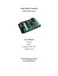
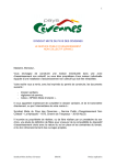
Evaluation Board (10.5 × 7 inch) ----- Photo.1 shows Photograph (Top View) of Board
l
User's Manual (this document)
3. Board Schematics
Figure. 1 shows the schematic of the evaluation board.
4. Functional Descriptions
4-1. Power Supply
Single +12V power supply.
Speaker amplifier operates at 5V, and all the other devices including
MSM7731-01 operates at 3V.
- 1 of 7 -
MSM7731-01 Evaluation Board User’s Manual
Ver. 2 April 1998
4-2. Port Control Interface
MSM7731-01 is designated to be set its device state either from the ports or from an MCU.
When evaluating MSM7731-01 with this evaluation board in port control mode, you should
set/change the device state by manipulating on-board switches (DSW1 ~ DSW5).
4-3. MCU (Micro Controller Unit) Interface
MSM7731-01 is designated to be set its device state either from the ports or from an MCU.
When evaluating MSM7731-01 with this evaluation board in MCU control mode, you can
further choose whether you would utilize on-board MCU or you would try an external MCU
you'll prepare by yourself,
4-3-1. On-board MCU Control
The descriptions hereunder explain the procedures for on-board MCU control;
a) On-board Switches
Set all of DSW6 to "ON".
b) CR WRITE
l
Set D7~D0 (SWITCH : SW2 ~ SW9) and A3~A0 (SWITCH : SW14~SW17) to
appropriate values referring to the device datasheet.
l
set R/W (SWITCH : SW18) to "W".
l
Set SET (SWITCH : SW19) "ON".
c) CR READ (for reconfirmation of CR values)
l
Set D7~D0 (SWITCH : SW2~SW9) and A3-A0 (SWITCH : SW14~SW17) to
appropriate values referring to the device datasheet.
l
Set R/W (SWITCH : SW18) to "R".
l
Set SET (SWITCH : SW19) "ON".
l
Your set CR values are now displayed on LED2~LED9.
4-3-2. External MCU Control
The descriptions hereunder explain the procedures for external MCU control;
a) Set all of DSW6 to "OFF".
b) Connect external the port of your MCU to TP4 (connected to DEN, DIN, DOUT,
EXCK pins of MSM7731-01).
- 2 of 7 -
MSM7731-01 Evaluation Board User’s Manual
Ver. 2 April 1998
4-4. Analog Interface
This board has 4 input/output jacks;
l
MIC
Acoustic side microphone input.
This is connected to AIN pin of MSM7731-01.
RV1 is variable register control for adjusting input gain.
l
SP
Acoustic side speaker output.
This is connected to on-board speaker amplifier LM4861 : National Semiconductor
(U13).
LM4861 input is connected to AOUT pin of MSM7731-01.
RV4 is variable register control for adjusting output gain.
Be careful NOT to saturate the input level of LM4861.
LM4861 device is 1W and 8 ohm load performance.
l
MIN
Line side analog input.
This is connected to LIN pin of MSM7731-01.
RV2 is variable register control for adjusting input gain.
l
MOUT
Line side analog output.
This is connected to LOUT pin of MSM7731-01.
RV5 is variable register control for adjusting output gain.
[Note] U15 are reserved for additional amplifiers (+5V).
4-5. Digital Interface
As line-side interface, MSM7731-01 provides you not only digital interface but also analogue
interface such as for IS-95 handsets. When you like to utilize this digital line-side interface
provided with MSM7731-01, connect the external digital interface to TP3 (SYNC, BCLK,
PCMI, PCMEI, PCMO, PCMEO pins of MSM7731).
JUMPER JP1 and JP2 are on-board pull-up/pull-down control.
("0" = pull-down ; "l" = pull-up ; "Remove JP×" = no pull-up/pull-down)
4-6. Clock Input
On board 19.2MHz X'tal is available.
[Note] XL1 is reserved for an oscillator.
- 3 of 7 -
MSM7731-01 Evaluation Board User’s Manual
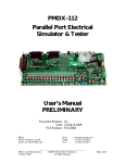
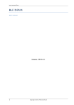
Figure 1
Board Schematic (1/3)
- 4 of 7 -
Ver. 2 April 1998
MSM7731-01 Evaluation Board User’s Manual
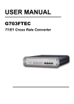
Figure 1
Ver. 2 April 1998
Board Schematic (2/3)
JP
LED
SB1 slide-type switch
SB2 snap-type switch SB3 toggle-type switch
SB4 slide-type switch
- 5 of 7 -
MSM7731-01 Evaluation Board User’s Manual
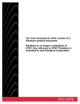
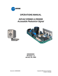
Figure 1
Board Schematic (2/3)
- 6 of 7 -
Ver. 2 April 1998
MSM7731-01 Evaluation Board User’s Manual
Photo.1 Photograph of the board (Top Vies)
- 7 of 7 -
Ver. 2 April 1998